Faculty of Engineering: Finite Element Analysis Report (Abaqus)
VerifiedAdded on 2022/09/09
|10
|1580
|18
Report
AI Summary
This report presents a finite element analysis (FEA) of a horizontal beam supported by vertical columns, conducted using Abaqus software. The analysis explores the structural integrity of the beam under concentrated and horizontal loads, comparing the performance of linear 3D and 3D shell elements. The report details the finite element models, mesh refinement studies, and the application of various material properties, including elastic modulus and yield strength. Results are presented in terms of stress distributions, displacement plots, and force-displacement graphs for different materials. The analysis includes a discussion of mesh convergence, reaction forces at supports, and a comparison of the two element types, highlighting the differences in deformation and stiffness. The report concludes with recommendations for future analysis, suggesting the use of linear 3D elements for improved accuracy and potential experimental verification.
Structure finite element analysis for applied loads and
boundary conditions
boundary conditions
Paraphrase This Document
Need a fresh take? Get an instant paraphrase of this document with our AI Paraphraser

Table of Contents
1 Background.................................................................................................................................. 3
2 Finite element models................................................................................................................... 3
2.1 Model with linear 3D elements.............................................................................................3
2.2 Model with 3D Shell elements.............................................................................................5
3 Results and Discussion................................................................................................................ 6
4 Conclusions and future recommendations....................................................................................9
1 Background
Finite element analysis is a numerical approach for assessing structural integrity of different structures
Based on the applied loads, material used and boundary conditions applied, each structure behaves
differently i.e. structural performance varies. Based on input material properties which are elastic
modulus, yield strength and ultimate tensile strength, the performance change.
In current analysis study, we have analysed a horizontal beam supported on 2 vertical columns with
concentrated loads applied at mid-spans. There are different analysis methods which depend on the
type of element used. Current analysis has used 2 different type of elements which are linear 3D
element and 3D shell element. The results and accuracy of each method depends on the extent of
refinement and deformation in the structure. These 2 methods are simulated and reported here.
2 Finite element models
Finite element models are prepared using 2 different types of elements and different sub-sections
report results from each type of analysis.
2.1 Analysis using linear 3D elements
In this section, model from linear 3D elements and corresponding results are discussed.
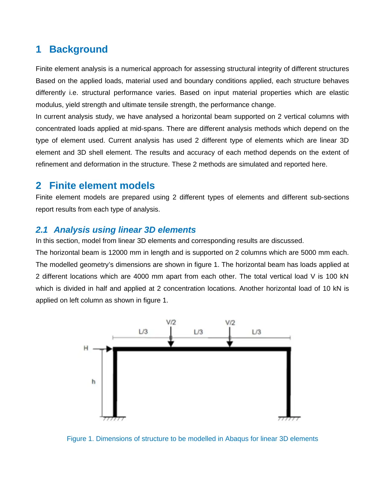
The horizontal beam is 12000 mm in length and is supported on 2 columns which are 5000 mm each.
The modelled geometry’s dimensions are shown in figure 1. The horizontal beam has loads applied at
2 different locations which are 4000 mm apart from each other. The total vertical load V is 100 kN
which is divided in half and applied at 2 concentration locations. Another horizontal load of 10 kN is
applied on left column as shown in figure 1.
Figure 1. Dimensions of structure to be modelled in Abaqus for linear 3D elements
⊘ This is a preview!⊘
Do you want full access?
Subscribe today to unlock all pages.

Trusted by 1+ million students worldwide
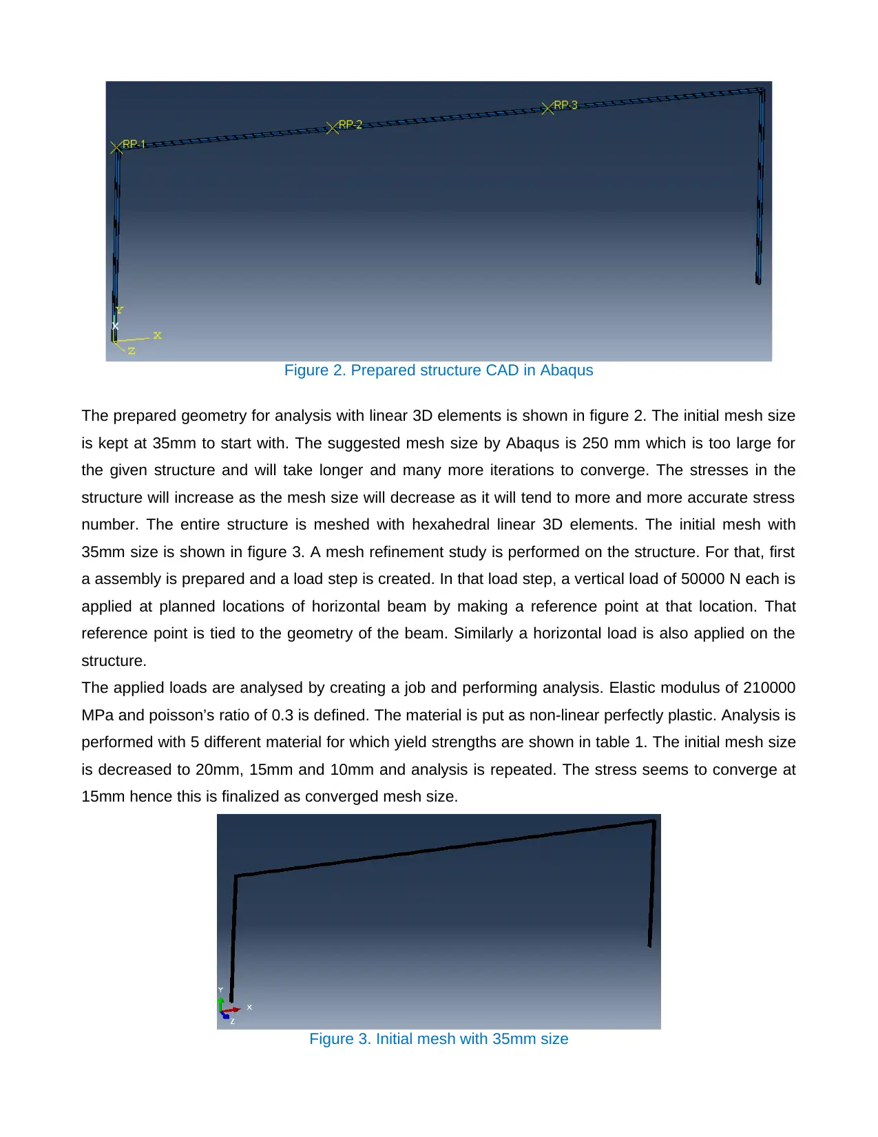
Figure 2. Prepared structure CAD in Abaqus
The prepared geometry for analysis with linear 3D elements is shown in figure 2. The initial mesh size
is kept at 35mm to start with. The suggested mesh size by Abaqus is 250 mm which is too large for
the given structure and will take longer and many more iterations to converge. The stresses in the
structure will increase as the mesh size will decrease as it will tend to more and more accurate stress
number. The entire structure is meshed with hexahedral linear 3D elements. The initial mesh with
35mm size is shown in figure 3. A mesh refinement study is performed on the structure. For that, first
a assembly is prepared and a load step is created. In that load step, a vertical load of 50000 N each is
applied at planned locations of horizontal beam by making a reference point at that location. That
reference point is tied to the geometry of the beam. Similarly a horizontal load is also applied on the
structure.
The applied loads are analysed by creating a job and performing analysis. Elastic modulus of 210000
MPa and poisson’s ratio of 0.3 is defined. The material is put as non-linear perfectly plastic. Analysis is
performed with 5 different material for which yield strengths are shown in table 1. The initial mesh size
is decreased to 20mm, 15mm and 10mm and analysis is repeated. The stress seems to converge at
15mm hence this is finalized as converged mesh size.
Figure 3. Initial mesh with 35mm size
Paraphrase This Document
Need a fresh take? Get an instant paraphrase of this document with our AI Paraphraser
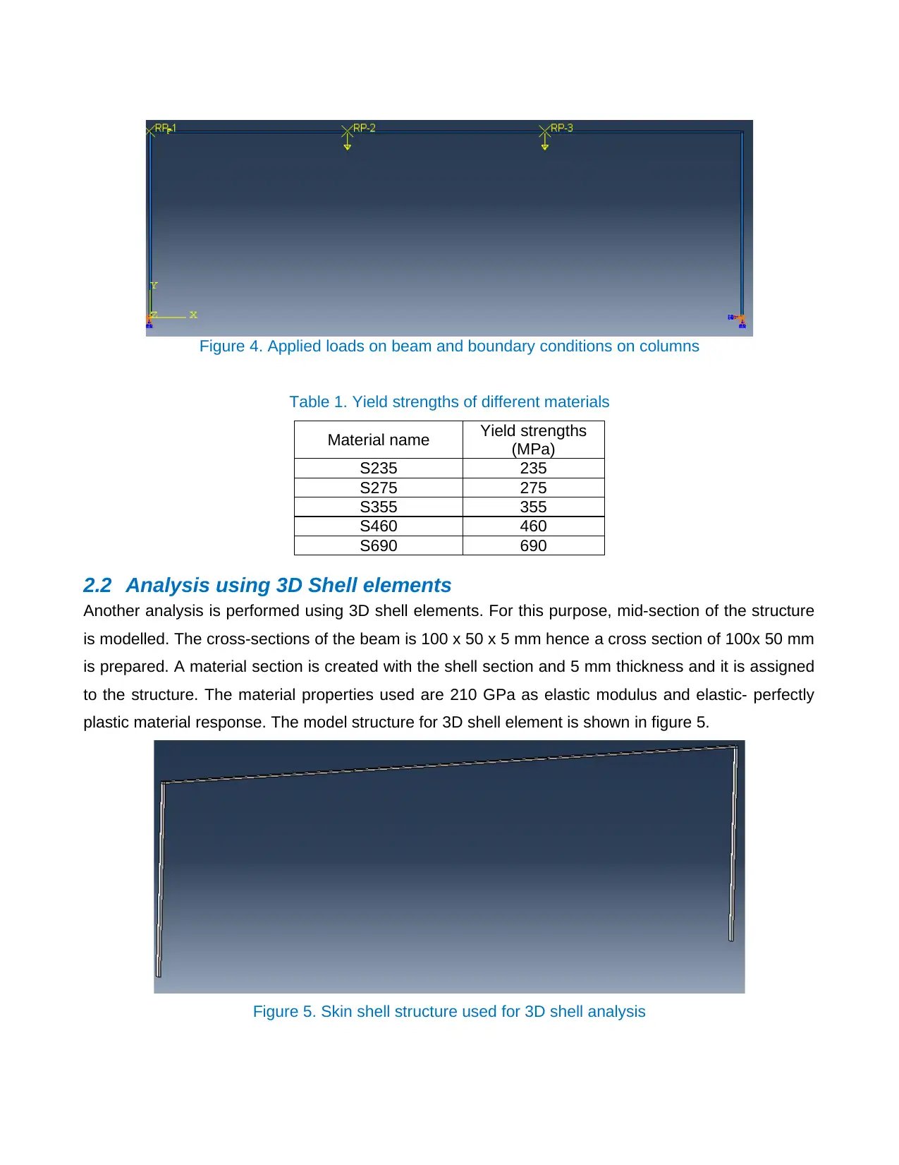
Figure 4. Applied loads on beam and boundary conditions on columns
Table 1. Yield strengths of different materials
Material name Yield strengths
(MPa)
S235 235
S275 275
S355 355
S460 460
S690 690
2.2 Analysis using 3D Shell elements
Another analysis is performed using 3D shell elements. For this purpose, mid-section of the structure
is modelled. The cross-sections of the beam is 100 x 50 x 5 mm hence a cross section of 100x 50 mm
is prepared. A material section is created with the shell section and 5 mm thickness and it is assigned
to the structure. The material properties used are 210 GPa as elastic modulus and elastic- perfectly
plastic material response. The model structure for 3D shell element is shown in figure 5.
Figure 5. Skin shell structure used for 3D shell analysis
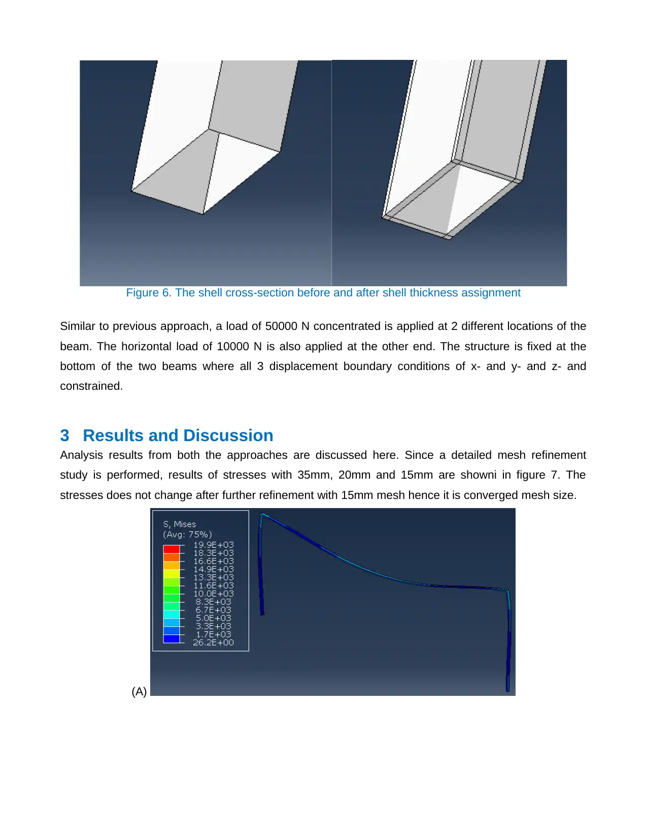
Figure 6. The shell cross-section before and after shell thickness assignment
Similar to previous approach, a load of 50000 N concentrated is applied at 2 different locations of the
beam. The horizontal load of 10000 N is also applied at the other end. The structure is fixed at the
bottom of the two beams where all 3 displacement boundary conditions of x- and y- and z- and
constrained.
3 Results and Discussion
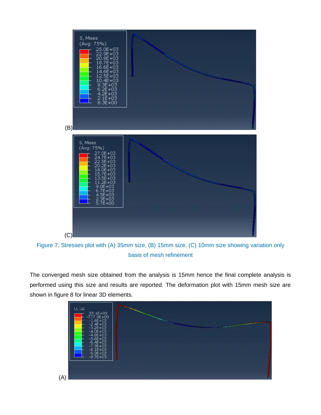
Analysis results from both the approaches are discussed here. Since a detailed mesh refinement
study is performed, results of stresses with 35mm, 20mm and 15mm are showni in figure 7. The
stresses does not change after further refinement with 15mm mesh hence it is converged mesh size.
(A)
⊘ This is a preview!⊘
Do you want full access?
Subscribe today to unlock all pages.

Trusted by 1+ million students worldwide
(B)
(C)
Figure 7. Stresses plot with (A) 35mm size, (B) 15mm size, (C) 10mm size showing variation only
basis of mesh refinement
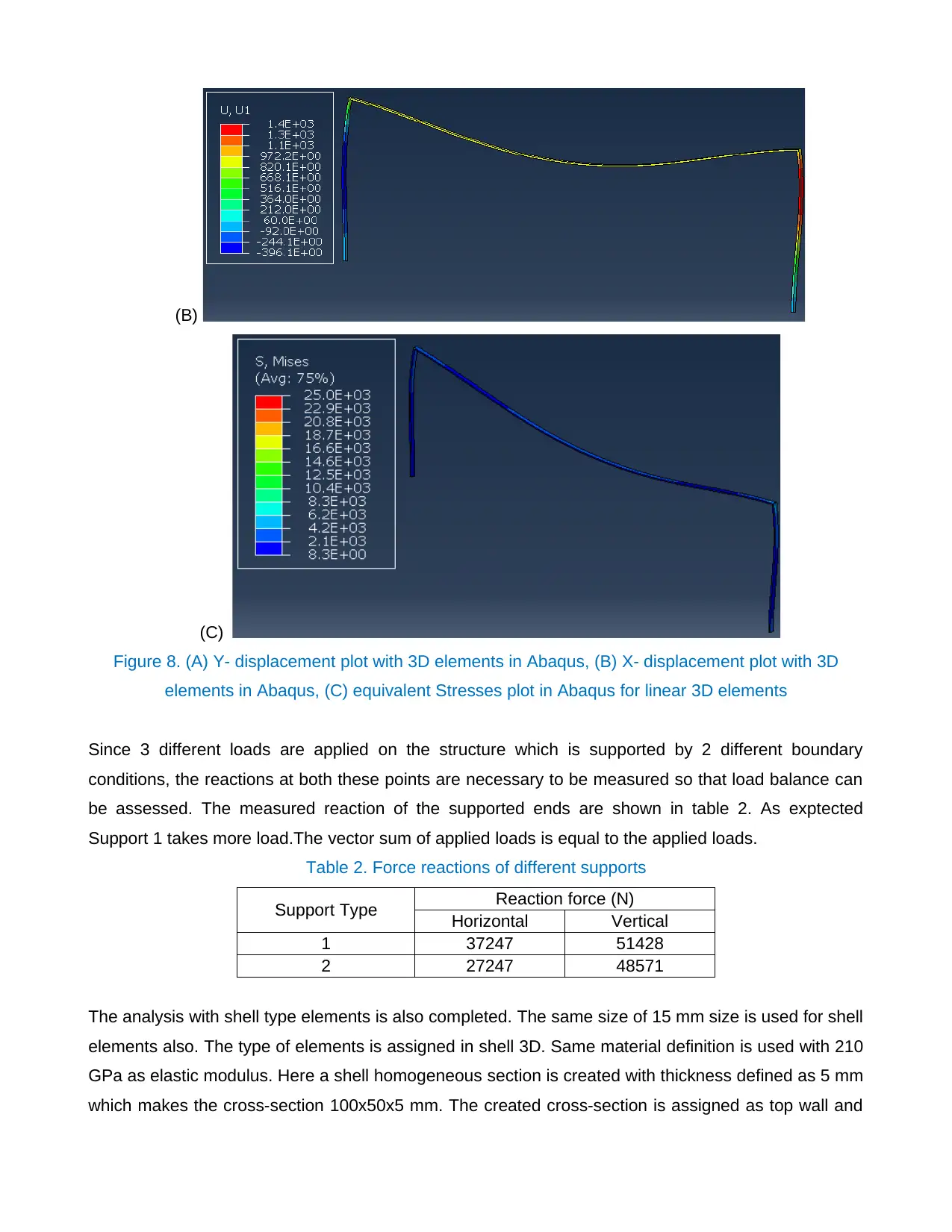
The converged mesh size obtained from the analysis is 15mm hence the final complete analysis is
performed using this size and results are reported. The deformation plot with 15mm mesh size are
shown in figure 8 for linear 3D elements.
(A)
Paraphrase This Document
Need a fresh take? Get an instant paraphrase of this document with our AI Paraphraser
(B)
(C)
Figure 8. (A) Y- displacement plot with 3D elements in Abaqus, (B) X- displacement plot with 3D
elements in Abaqus, (C) equivalent Stresses plot in Abaqus for linear 3D elements
Since 3 different loads are applied on the structure which is supported by 2 different boundary
conditions, the reactions at both these points are necessary to be measured so that load balance can
be assessed. The measured reaction of the supported ends are shown in table 2. As exptected
Support 1 takes more load.The vector sum of applied loads is equal to the applied loads.
Table 2. Force reactions of different supports
Support Type Reaction force (N)
Horizontal Vertical
1 37247 51428
2 27247 48571
The analysis with shell type elements is also completed. The same size of 15 mm size is used for shell
elements also. The type of elements is assigned in shell 3D. Same material definition is used with 210
GPa as elastic modulus. Here a shell homogeneous section is created with thickness defined as 5 mm
which makes the cross-section 100x50x5 mm. The created cross-section is assigned as top wall and
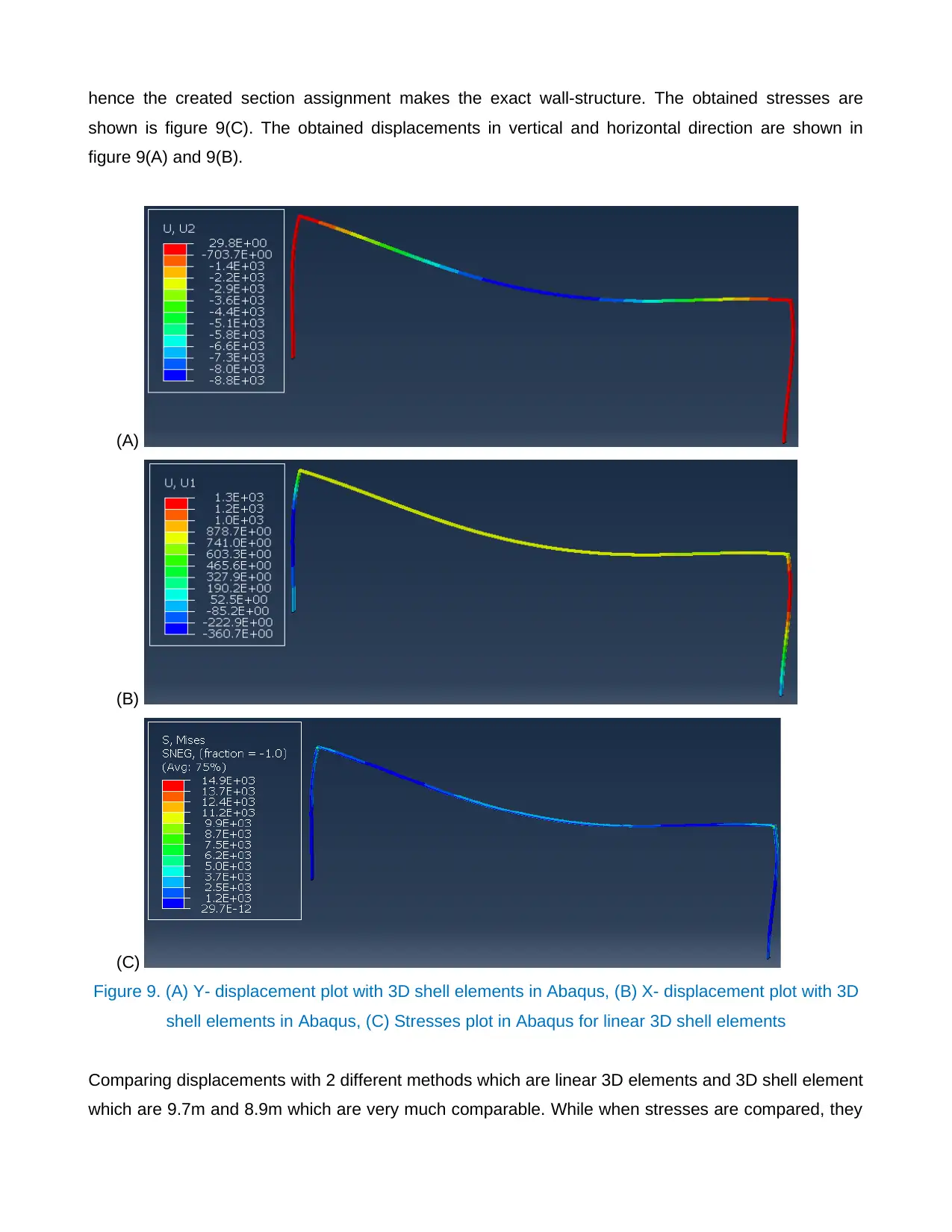
hence the created section assignment makes the exact wall-structure. The obtained stresses are
shown is figure 9(C). The obtained displacements in vertical and horizontal direction are shown in
figure 9(A) and 9(B).
(A)
(B)
(C)
Figure 9. (A) Y- displacement plot with 3D shell elements in Abaqus, (B) X- displacement plot with 3D
shell elements in Abaqus, (C) Stresses plot in Abaqus for linear 3D shell elements
Comparing displacements with 2 different methods which are linear 3D elements and 3D shell element
which are 9.7m and 8.9m which are very much comparable. While when stresses are compared, they
⊘ This is a preview!⊘
Do you want full access?
Subscribe today to unlock all pages.

Trusted by 1+ million students worldwide
are comparatively different. Similarly for horizontal direction, displacement with 3D elements model is
1.4 m while with shell element model is 1.3 m hence indicates more stiffness with shell elements. Shell
model adds and makes model more stiffened and hence deformations are less with shell model. Again
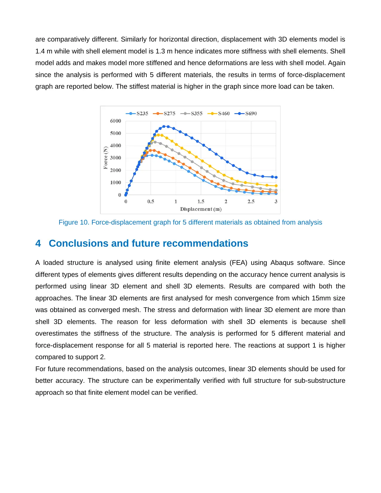
since the analysis is performed with 5 different materials, the results in terms of force-displacement
graph are reported below. The stiffest material is higher in the graph since more load can be taken.
Figure 10. Force-displacement graph for 5 different materials as obtained from analysis
4 Conclusions and future recommendations
A loaded structure is analysed using finite element analysis (FEA) using Abaqus software. Since
different types of elements gives different results depending on the accuracy hence current analysis is
performed using linear 3D element and shell 3D elements. Results are compared with both the
approaches. The linear 3D elements are first analysed for mesh convergence from which 15mm size
was obtained as converged mesh. The stress and deformation with linear 3D element are more than
shell 3D elements. The reason for less deformation with shell 3D elements is because shell
overestimates the stiffness of the structure. The analysis is performed for 5 different material and
force-displacement response for all 5 material is reported here. The reactions at support 1 is higher
compared to support 2.
For future recommendations, based on the analysis outcomes, linear 3D elements should be used for
better accuracy. The structure can be experimentally verified with full structure for sub-substructure
approach so that finite element model can be verified.
1 out of 10
Related Documents
Your All-in-One AI-Powered Toolkit for Academic Success.
+13062052269
info@desklib.com
Available 24*7 on WhatsApp / Email
![[object Object]](/_next/static/media/star-bottom.7253800d.svg)
Unlock your academic potential
Copyright © 2020–2026 A2Z Services. All Rights Reserved. Developed and managed by ZUCOL.


