Structures: Solved Questions and Answers

Verified

Added on  2023/06/13

|14
|1698
|77
AI Summary
This document contains solutions to five questions related to structures, including calculations for neutral axis parameters, ultimate moment, shear reinforcement, and torsion. The bibliography lists relevant research articles on the topic.

Contribute Materials

Your contribution can guide someone’s learning journey. Share your documents today.
Document Page
Structures 1
STRUCTURES
By (Name)
Course
Professor’s name
University name
City, State
Date of submission

Secure Best Marks with AI Grader

Need help grading? Try our AI Grader for instant feedback on your assignments.
Document Page
Structures 2
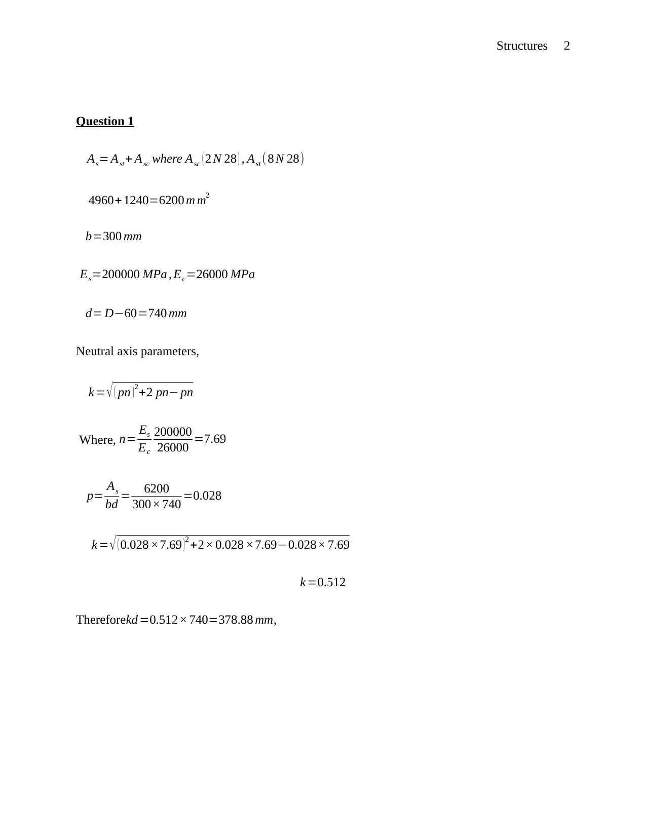
Question 1
As= Ast+ Asc where Asc ( 2 N 28 ) , Ast ( 8 N 28)
4960+ 1240=6200 m m2
b=300 mm
Es=200000 MPa , Ec=26000 MPa
d= D60=740 mm
Neutral axis parameters,
k = ( pn ) 2+2 pn pn
Where, n= Es
Ec
200000
26000 =7.69
p= As
bd = 6200
300× 740 =0.028
k = ( 0.028 ×7.69 )2 +2× 0.028 ×7.690.028× 7.69
k =0.512
Thereforekd =0.512× 740=378.88 mm,
Document Page
Structures 3
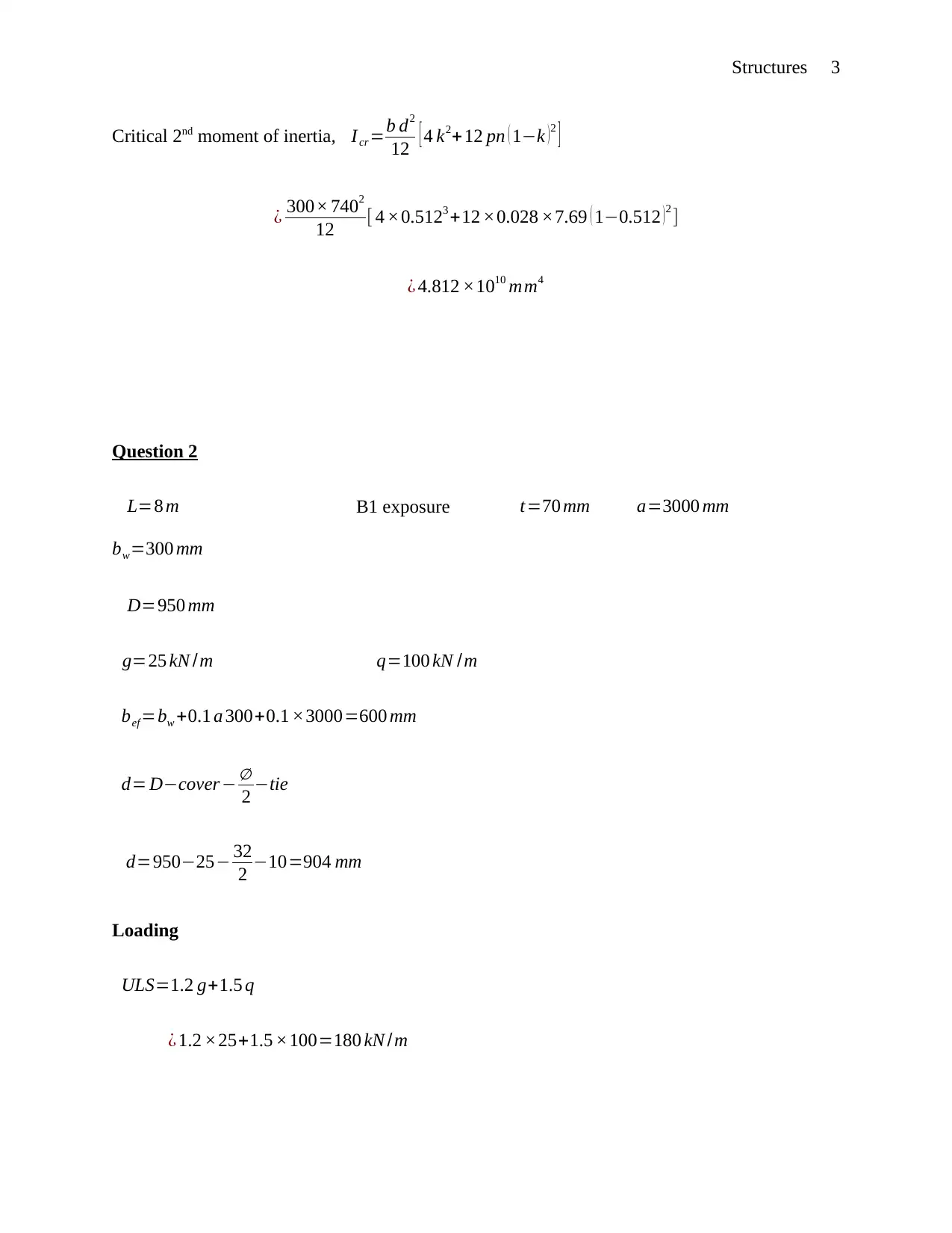
Critical 2nd moment of inertia, Icr =b d2
12 [ 4 k2+12 pn ( 1k )2 ]
¿ 300× 7402
12 [ 4 ×0.5123 +12 ×0.028 ×7.69 ( 10.512 )2 ]
¿ 4.812 ×1010 mm4
Question 2
L=8 m B1 exposure t=70 mm a=3000 mm
bw=300 mm
D=950 mm
g=25 kN /m q=100 kN /m
bef =bw +0.1 a 300+0.1 ×3000=600 mm
d= Dcover
2 tie
d=95025 32
2 10=904 mm
Loading
ULS=1.2 g+1.5 q
¿ 1.2 ×25+1.5 ×100=180 kN /m
Document Page
Structures 4
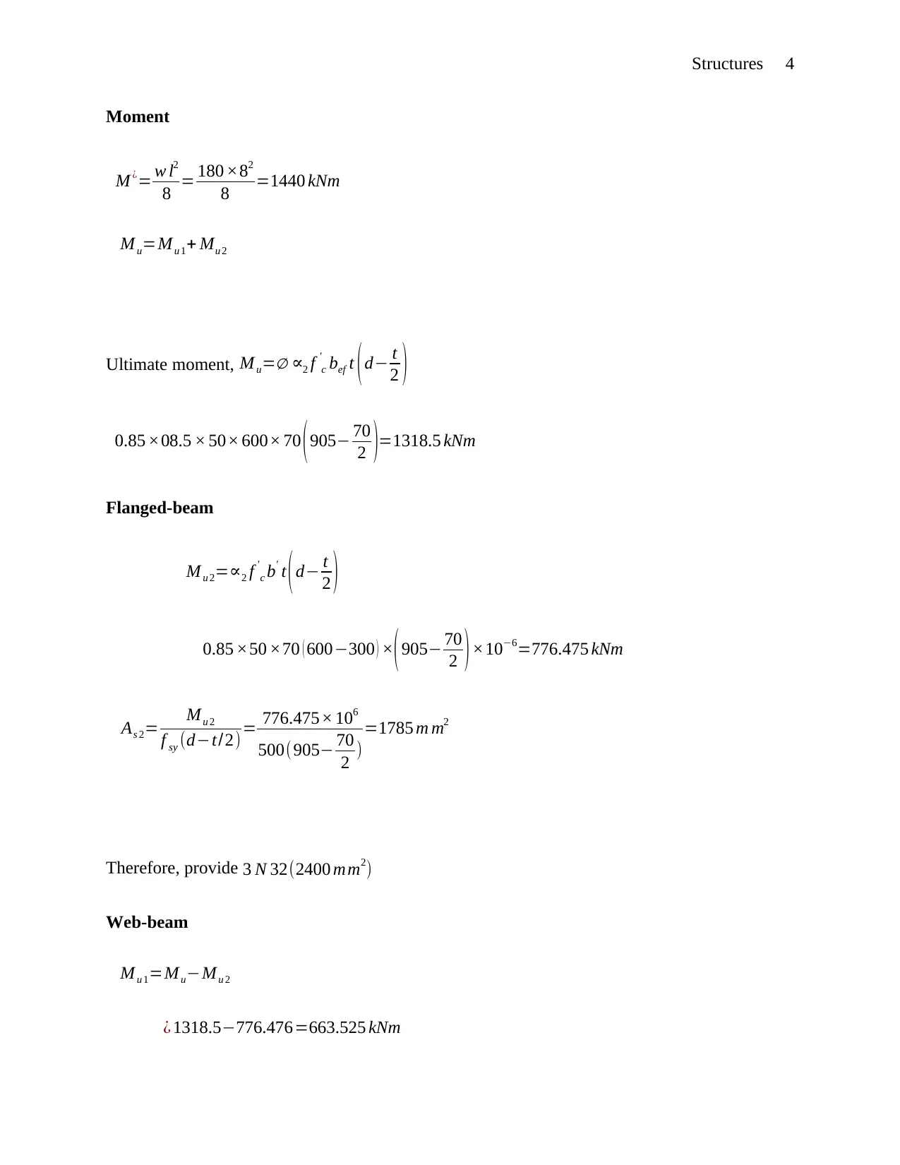
Moment
M ¿= w l2
8 = 180 ×82
8 =1440 kNm
Mu=Mu 1+ Mu 2
Ultimate moment, M u= 2 f '
c bef t ( d t
2 )
0.85 ×08.5 × 50× 600× 70 ( 905 70
2 )=1318.5 kNm
Flanged-beam
M u 2=2 f '
c b' t (d t
2 )
0.85 ×50 ×70 ( 600300 ) × (905 70
2 )×106=776.475 kNm
As 2= Mu 2
f sy (dt/2)= 776.475× 10⁶
500(905 70
2 )
=1785 m m2
Therefore, provide 3 N 32(2400 mm2)
Web-beam
Mu 1=MuMu 2
¿ 1318.5776.476=663.525 kNm

Secure Best Marks with AI Grader

Need help grading? Try our AI Grader for instant feedback on your assignments.
Document Page
Structures 5
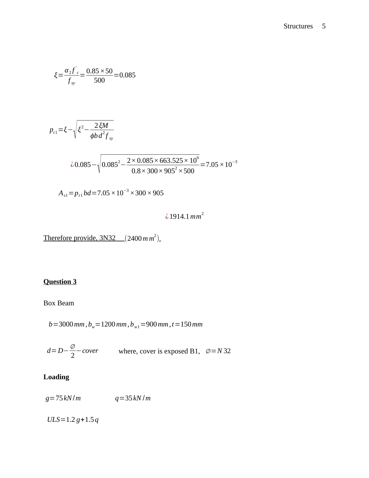
ξ= α2 f '
c
f sy
= 0.85 ×50
500 =0.085
pt 1 =ξ ξ2 2 ξM
ϕb d2 f sy
¿ 0.085 0.0852 2× 0.085× 663.525× 106
0.8× 300× 9052 ×500 =7.05 ×10³
As1 =pt 1 bd=7.05 ×103 ×300 × 905
¿ 1914.1 mm2
Therefore provide, 3N32 (2400 m m2 )
Question 3
Box Beam
b=3000 mm , bw=1200 mm , bw1 =900 mm , t=150 mm
d= D
2 cover where, cover is exposed B1, =N 32
Loading
g=75 kN /m q=35 kN / m
ULS=1.2 g+1.5 q
Document Page
Structures 6
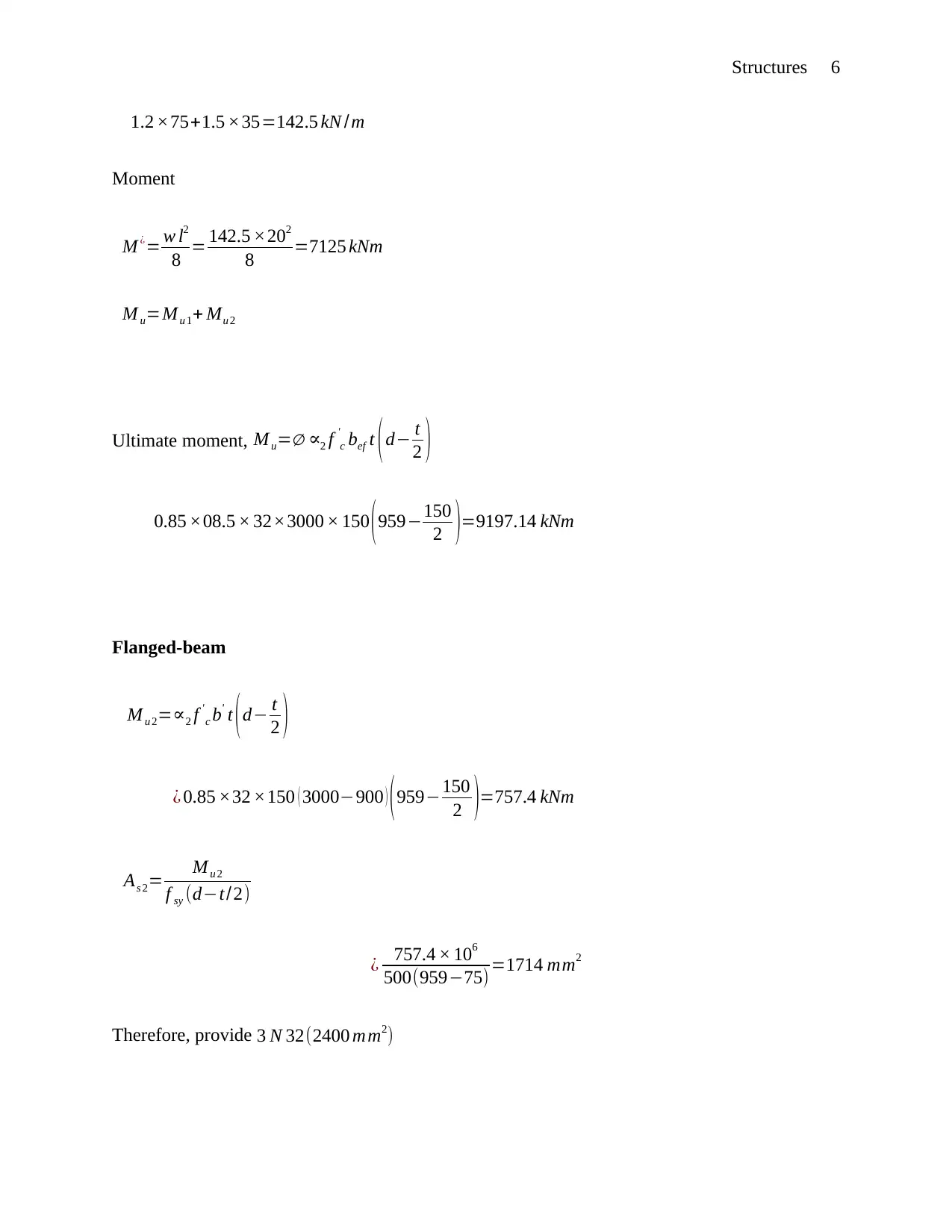
1.2 ×75+1.5 ×35=142.5 kN / m
Moment
M ¿= w l2
8 = 142.5 ×202
8 =7125 kNm
M u=M u 1+ Mu 2
Ultimate moment, M u= 2 f '
c bef t ( d t
2 )
0.85 ×08.5 × 32×3000 × 150 (959150
2 )=9197.14 kNm
Flanged-beam
Mu 2=2 f '
c b' t (d t
2 )
¿ 0.85 ×32 ×150 ( 3000900 ) (959150
2 )=757.4 kNm
As 2= M u 2
f sy (dt/2)
¿ 757.4 × 10⁶
500(95975) =1714 mm2
Therefore, provide 3 N 32(2400 mm2)
Document Page
Structures 7
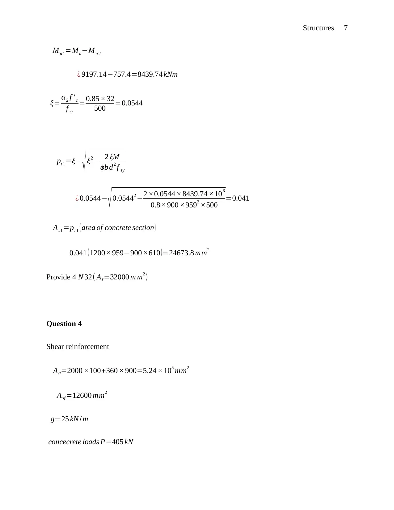
Mu 1=MuMu 2
¿ 9197.14757.4=8439.74 kNm
ξ= α 2 f ' c
f sy
=0.85 × 32
500 =0.0544
pt 1 =ξ ξ2 2 ξM
ϕb d2 f sy
¿ 0.0544 0.05442 2 ×0.0544 × 8439.74 ×106
0.8× 900 ×9592 ×500 =0.041
As1 =pt 1 ( area of concrete section )
0.041 ( 1200× 959900 ×610 ) =24673.8 mm2
Provide 4 N 32( As=32000 m m2)
Question 4
Shear reinforcement
Ag=2000 ×100+360 × 900=5.24 × 105 mm2
Asf =12600 mm2
g=25 kN /m
concecrete loads P=405 kN

Paraphrase This Document

Need a fresh take? Get an instant paraphrase of this document with our AI Paraphraser
Document Page
Structures 8
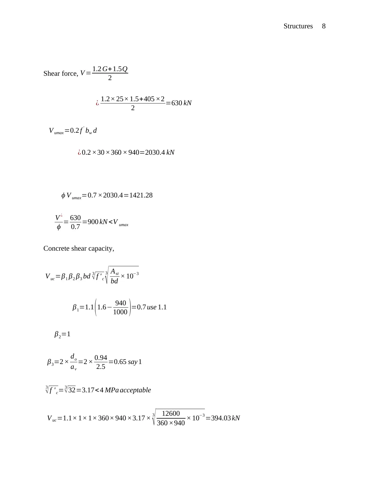
Shear force, V = 1.2 G+1.5Q
2
¿ 1.2× 25× 1.5+405 ×2
2 =630 kN
V umax =0.2 f ' bw d
¿ 0.2 ×30 ×360 × 940=2030.4 kN
ϕ V umax=0.7 ×2030.4=1421.28
V ¿
ϕ = 630
0.7 =900 kN <V umax
Concrete shear capacity,
V uc=β1 β2 β3 bd 3
f ' c
3
Ast
bd × 103
β1=1.1 (1.6 940
1000 )=0.7 use 1.1
β2=1
β3=2 × do
av
=2 × 0.94
2.5 =0.65 say 1
3
f 'c=3
32=3.17< 4 MPa acceptable
V uc=1.1× 1× 1× 360× 940 ×3.17 × 3
12600
360 ×940 × 103 =394.03 kN
Document Page
Structures 9
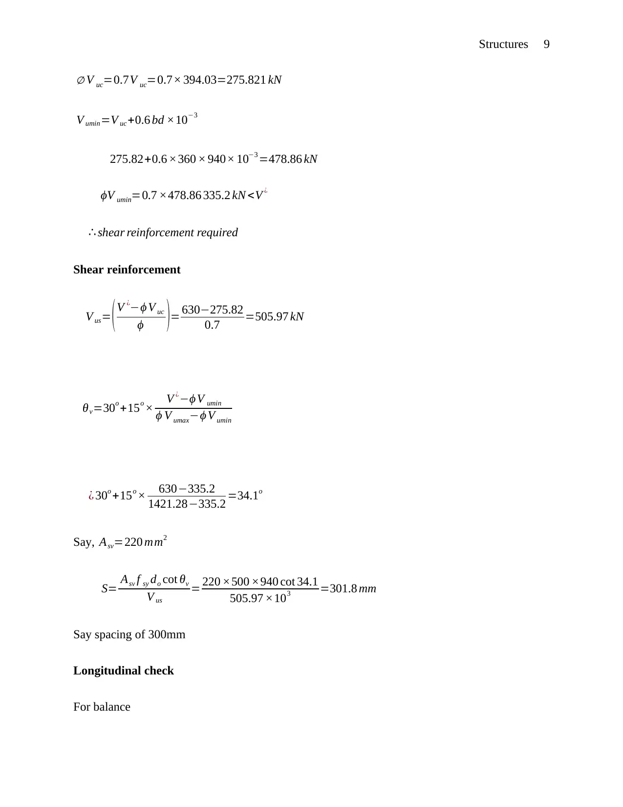
V uc=0.7V uc=0.7× 394.03=275.821 kN
V umin=V uc+0.6 bd ×103
275.82+0.6 ×360 × 940× 103 =478.86 kN
ϕV umin=0.7 ×478.86 335.2 kN <V ¿
shear reinforcement required
Shear reinforcement
V us= ( V ¿ϕ V uc
ϕ )= 630275.82
0.7 =505.97 kN
θv=30o +15o × V ¿ϕ V umin
ϕ V umaxϕ V umin
¿ 30o +15o × 630335.2
1421.28335.2 =34.1o
Say, Asv=220 mm2
S= Asv f sy do cot θv
V us
= 220 ×500 ×940 cot 34.1
505.97 ×103 =301.8 mm
Say spacing of 300mm
Longitudinal check
For balance
Document Page
Structures 10
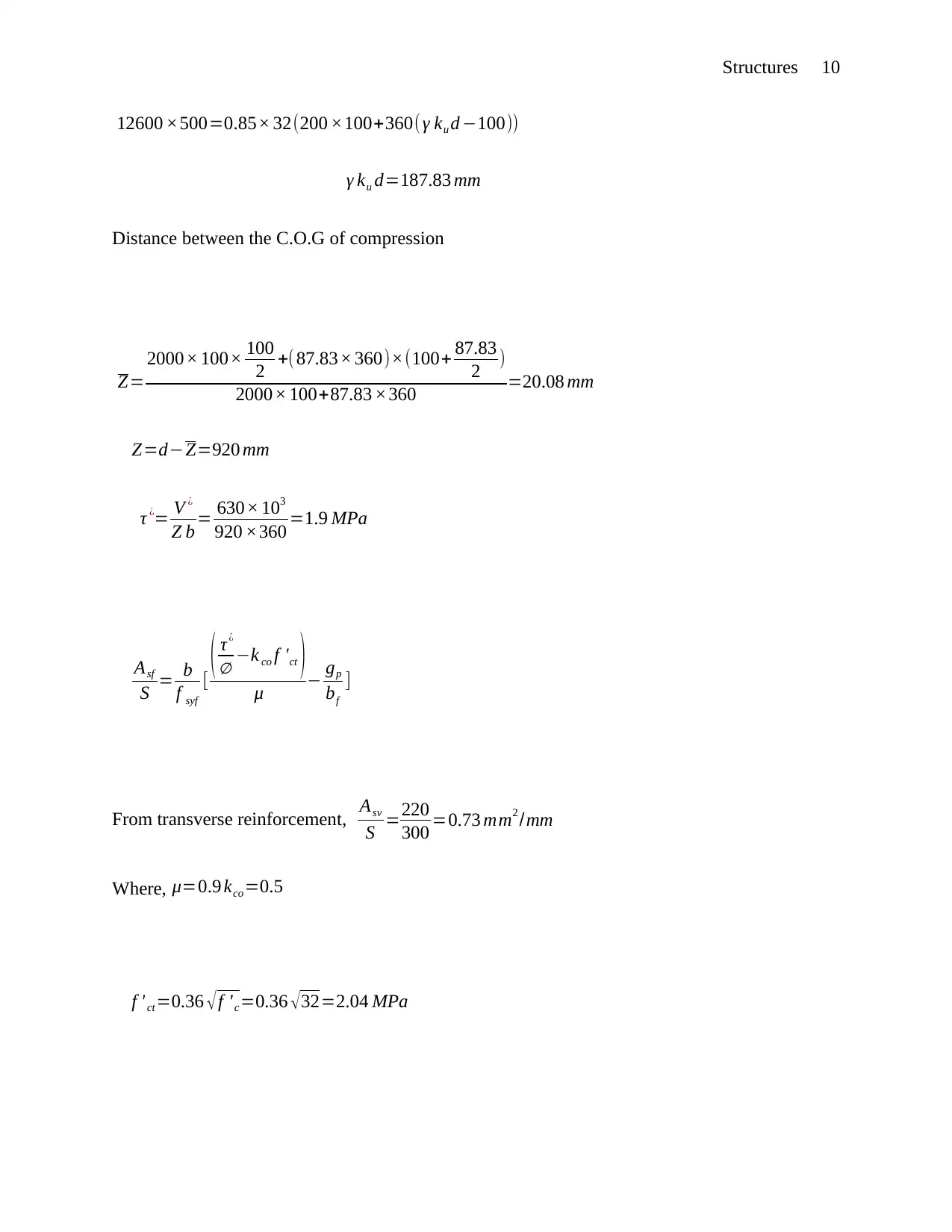
12600 ×500=0.85× 32(200 ×100+360( γ ku d 100))
γ ku d=187.83 mm
Distance between the C.O.G of compression
Ζ=
2000× 100× 100
2 +( 87.83× 360)×(100+ 87.83
2 )
2000× 100+87.83 ×360 =20.08 mm
Ζ=dΖ=920 mm
τ ¿= V ¿
Ζ b = 630× 103
920 ×360 =1.9 MPa
Asf
S = b
f syf
[ ( τ¿
k co f 'ct )
μ gp
bf
]
From transverse reinforcement, Asv
S =220
300 =0.73 mm2 /mm
Where, μ=0.9 kco=0.5
f ' ct =0.36 f 'c=0.36 32=2.04 MPa

Secure Best Marks with AI Grader

Need help grading? Try our AI Grader for instant feedback on your assignments.
Document Page
Structures 11
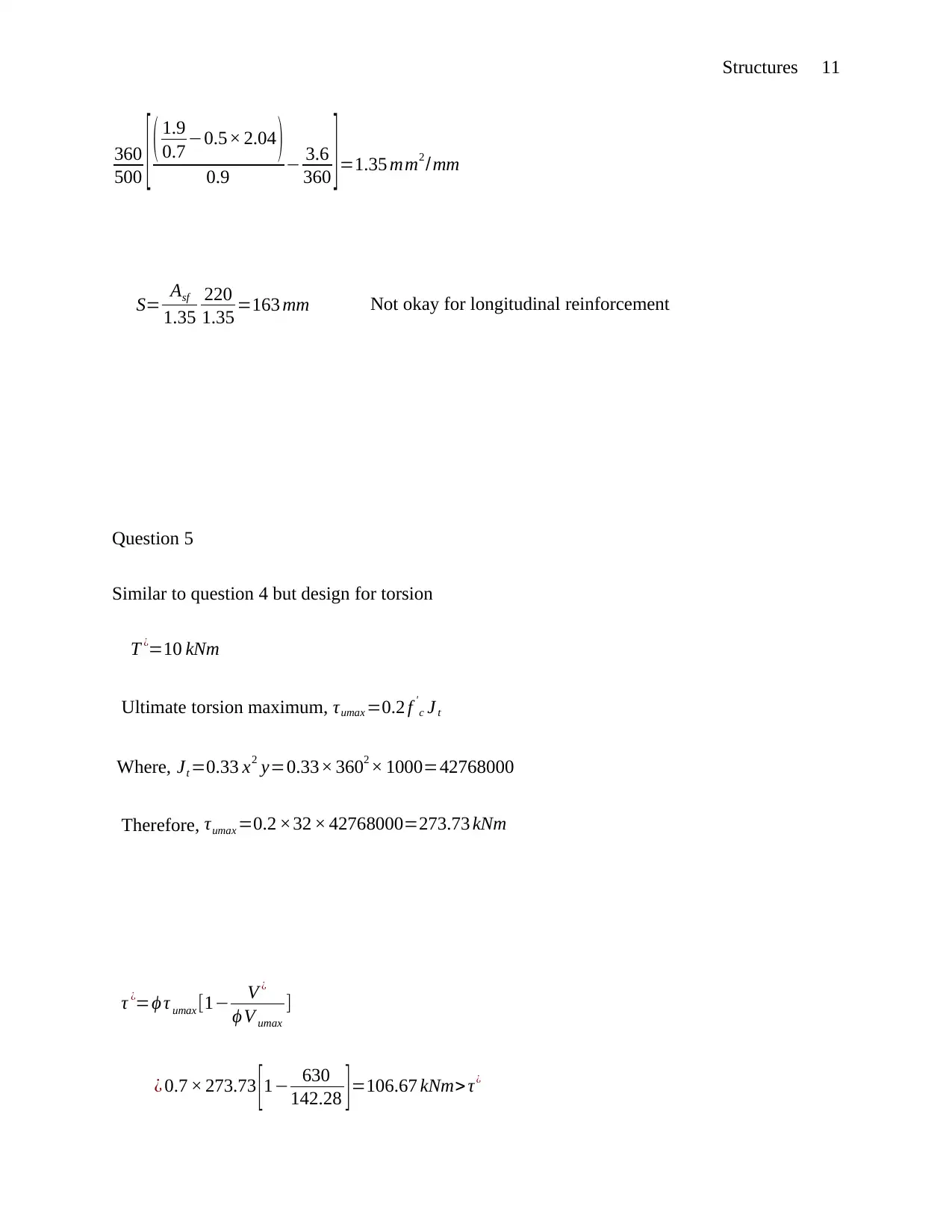
360
500 [ ( 1.9
0.7 0.5× 2.04 )
0.9 3.6
360 ]=1.35 mm2 /mm
S= Asf
1.35
220
1.35 =163 mm Not okay for longitudinal reinforcement
Question 5
Similar to question 4 but design for torsion
T ¿=10 kNm
Ultimate torsion maximum, τumax =0.2 f '
c J t
Where, Jt =0.33 x2 y=0.33× 3602 × 1000=42768000
Therefore, τumax =0.2 ×32 × 42768000=273.73 kNm
τ ¿=ϕ τ umax [1 V ¿
ϕ V umax
]
¿ 0.7 × 273.73 [ 1 630
142.28 ] =106.67 kNm> τ¿
Document Page
Structures 12
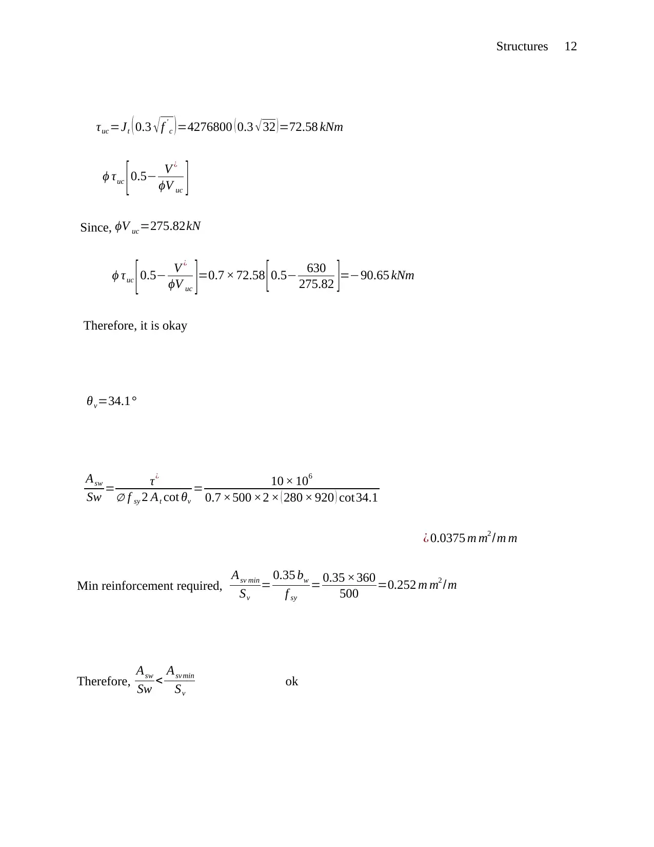
τuc =Jt ( 0.3 f '
c )=4276800 ( 0.3 32 )=72.58 kNm
ϕ τuc [0.5 V ¿
ϕV uc ]
Since, ϕV uc=275.82kN
ϕ τuc [0.5 V ¿
ϕV uc ]=0.7 × 72.58 [0.5 630
275.82 ]=90.65 kNm
Therefore, it is okay
θv=34.1°
Asw
Sw = τ¿
f sy 2 At cot θv
= 10 × 106
0.7 ×500 ×2 × ( 280 × 920 ) cot34.1
¿ 0.0375 m m2 /m m
Min reinforcement required, Asv min
Sv
= 0.35 bw
f sy
= 0.35 ×360
500 =0.252 m m2 /m
Therefore, Asw
Sw < Asvmin
Sv
ok
Document Page
Structures 13
Bibliography
Bernardo, L.F.A. and Lopes, S.M.R., 2004. Neutral axis depth versus flexural ductility in high-
strength concrete beams. Journal of Structural Engineering, 130(3), pp.452-459.
Chan, C.L., Khalid, Y.A., Sahari, B.B. and Hamouda, A.M.S., 2002. Finite element analysis of
corrugated web beams under bending. Journal of Constructional Steel Research, 58(11),
pp.1391-1406.
Eltaher, M.A., Alshorbagy, A.E. and Mahmoud, F.F., 2013. Determination of neutral axis
position and its effect on natural frequencies of functionally graded macro/nanobeams.
Composite Structures, 99, pp.193-201.

Paraphrase This Document

Need a fresh take? Get an instant paraphrase of this document with our AI Paraphraser
Document Page
Structures 14
El-Sayed, A.K., El-Salakawy, E.F. and Benmokrane, B., 2006. Shear strength of FRP-reinforced
concrete beams without transverse reinforcement. ACI Structural Journal, 103(2), p.235.
Foster, S., 2010, December. 12 Design of FRC beams for shear using the VEM and the draft
Model Code approach. In Shear and Punching Shear in RC and FRC Elements: Technical
Report: Proceedings of a Workshop Held on 15-16 October 2010, in Salò, Lake Garda, Italy
(Vol. 57, p. 195). fib Fédération internationale du béton.
Loo, Y.C. and Chowdhury, S.H., 2010. Reinforced and Prestressed Concrete: Analysis and
Design with Emphasis on Application of AS3600-2009. Cambridge University Press.
Marčiukaitis, G., Jonaitis, B. and Valivonis, J., 2006. Analysis of deflections of composite slabs
with profiled sheeting up to the ultimate moment. Journal of Constructional Steel Research,
62(8), pp.820-830.
Tsavdaridis, K.D. and D'Mello, C., 2011. Web buckling study of the behaviour and strength of
perforated steel beams with different novel web opening shapes. Journal of Constructional Steel
Research, 67(10), pp.1605-1620.
Tang, Y.Q., Chen, L.Q. and Yang, X.D., 2008. Natural frequencies, modes and critical speeds of
axially moving Timoshenko beams with different boundary conditions. International Journal of
mechanical sciences, 50(10-11), pp.1448-1458.
Zararis, P.D., 2003. Shear strength and minimum shear reinforcement of reinforced concrete
slender beams. Structural Journal, 100(2), pp.203-214.
1 out of 14
circle_padding
hide_on_mobile
zoom_out_icon
[object Object]

Your All-in-One AI-Powered Toolkit for Academic Success.

Available 24*7 on WhatsApp / Email

[object Object]