Time Delay Analysis and Control Design for Quadrotor UAV (ENS5253)
VerifiedAdded on 2023/01/19
|9
|2253
|72
Report
AI Summary
This report investigates the impact of time delay on quadrotor UAV control systems, focusing on the challenges posed by wireless communication and signal transmission delays. It identifies factors contributing to time delay and explores solutions using PV and P controllers to achieve stability and improve transient responses. The report details the implementation of time-delay estimation methods using characteristic roots and Lambert W function in MATLAB/Simulink, using a Parrot AR. Drone 2.0 UAV as a case study. Numerical and analytical approaches are employed to estimate time delay, and appropriate controller gains are applied to mitigate the effects of control signal saturation. The findings demonstrate the effectiveness of analytical solutions of Delay Differential Equations (DDEs) and Ordinary Differential Equations (ODEs) for time delay estimation in internet-based and quadrotor UAV control systems.
Student First Name, Surname – ID Number
Running head: TIME DELAY ANALYSIS FOR QUADROTOR (UAV) ANDR CONTROL
DESIGN
1.0 Introduction
The Unmanned aerial vehicles (UAV) are widely applied in most fields nowadays. In the
past they were only used in military application, but as time goes by they were started being
used in different fields. The drones are used in agriculture for distribution of chemicals and
observation. Also they are used for patrolling of a vast area like forests, borders. Even the
rescues missions such as fires, floods and hurricanes they can be useful to observe and send
the real time information which is useful the concerned group. Since the invention of them,
surveying has been easy and enjoying. (Randal W. Beard, 2012)
1.1 Description of the Control Objectives
The main objective of this study is to investigate quadrotor is to familiarise the control
scheme and instinctive procedure tune gaining. The controllers designed are to reach the
requirement in technical manners:
The controller should be able to achieve overall time delay stabilization
The controller should be able to achieve stabilization when there is devices reading
measurements causing time delay i.e. proximity sensors
The controller must give reference of the time delay control for signal processing
motion devices
The controller must achieve host computer processing capability in relation to time
delay.
2.0 Background
Drone term is usually used by the public and media, for all types robotic aircrafts. But
from the technical point of there are many kinds of unmanned aircrafts. (Carey, 2016)There
are three categories of pilotless aircrafts: drones, remotely piloted vehicles (RPV) and
unmanned aerial vehicles (UAV).They differ due to their kinds of missions, size, fight,
envelope as well as the operation autonomy level. For instance the UAV are more
autonomous while the RPV are controlled remotely. Since 1950s, they have been used but off
recent in wide application. In years of their invention were being used more military only but
nowadays are used in Agriculture, rescue missions, monitoring, photograph and filming, and
recognisance missions. Even civilians, they own them. The time delay has been a major issue
because of the use wireless transfer of signal. (Faust, 2016)The pilotless aircrafts have closed
loop systems. There have been many researches on to solve the problem of time delay.
Innovations are being made day by to improve the performance on time delay.
Paraphrase This Document
Need a fresh take? Get an instant paraphrase of this document with our AI Paraphraser

Student First Name, Surname – ID Number
Running head: TIME DELAY ANALYSIS FOR QUADROTOR (UAV) ANDR CONTROL
DESIGN
3.0 Objective Selection
3.1 Identification of the Control Objective
Controlling the unmanned aerial vehicles of the type known as quadrotors is the focus
of this study. The study will analyse and try to solve the problem of time delay. One of the
existing challenges is about efficient system control for the UAVs is signal transmission
delay existence which has non-linear impacts on performance of the flight. For the quadrotor,
this study is to identify also the factors causing time delay the wireless system of UAVs.. If
the factors causing delay time are identified and regulated also the required feedback can be
achieved from the quadrotor.
3.2 PV and P Controllers
.
The transient feedbacks measured and in comparison to time-domain obtained
descriptions by the use of the characteristic which is dominant root being based on Lambert
function, that can be written in system parameter terms delay included. The proportional
controllers are employed for estimation of responses generated. (Rupprecht, 2015) The time
delay impacts on transient impacts as well as analysing stability. PV controllers are the one
which will control the quadrotor system remotely or automously. The designing of
proportional plus velocity (PV) controls is to get good transient responses or feedback. In the
quadrotor the controllers performance is analysed on altitude, velocity and lateral distance.
The controllers are to estimate the UAV time delay during transmission. (Angelov, 2012)The
altitude model also AR. Drone 2.0 systems of control are provided.
This system of the integrator 1/S in the transfer functions of a closed loop. The
feedback controllers of P and PV regulate speed in vertical direction. Whereby, P-feedback
is for creation of transient responses for time delay estimation. Also PV-feedback is for
improvement of transient response. The closed-loop for time delay system for P controller is
given by
(4)
The system of time-delay is a retard type. The time delay for PV controller in closed
loop is as
(5)
4.0 System Implementation

TIME DELAY ANALYSIS FOR QUADROTOR (UAV) ANDR CONTROL DESIGN
4.1 Time-Delay
During the designing and analysis for UAVs, the transmission delay existence which is
as a result of wireless communication is among the critical challenges .The delays estimations
and analysis of their impacts are nonlinear. The method for delay is introduced by the use of
transient feedbacks of a quadrotor type of unmanned aerial vehicles as well as analytical
solution DDEs (delay differential equations). Data sets collected from the experiment is of
the approach of time domain for first order DDEs is applied for analysing is used Dominant
characteristic can root amongst infinite feedbacks usually analysis is done through root
locations. Estimation based on results, the proportional plus controllers are proposed to
improve transient altitude feedbacks.
4.2 Estimate of Delay Time by Use of Characteristic Roots
Problem estimation formulation is done by the use of analytical solutions form of DDEs
in terms of scalar Lambert W function. (Daras, 2010)Considering the first order of scalar
homogenous DDE:
The characteristic root equation of (1) is given by
Then, the characteristic root equation in (2) can be solved as
The Lambert W function is as follows: W(x) eW(x) =X as it from characteristic root
equation S, with its parameters a0, a1 as well as Td. The above solution helps in finding the
time delay and feedback of the quadrotor. Refer in Appendix 1
4.3 Software Configuration
The quadrotor used is UAV, Parrot AR. Drone 2.0 in the study. The MALAB/Simulink
is used for control of the quadrotor via the Wi-Fi which can bring in the time delay in it
dynamics. The MATLAB/Simulink is used to encode as well as decoding of navigation
process. (Attaway, 2012)The Lambert W equation is in MATLAB as ‘lambertw’ (Leite,
2010) (Alaimo, 2013).Using an Example in Appendix 2, solving it we get the chart below.
The embedded function ‘fsolve’ then the internet based feedback control is given a
TIME DELAY ANALYSIS OF QUAQROTOR (UAV) Page 3 of 9
Date: 16/04/2019
Control Systems ENS5253 – Semester 1, 2019
⊘ This is a preview!⊘
Do you want full access?
Subscribe today to unlock all pages.

Trusted by 1+ million students worldwide
TIME DELAY ANALYSIS FOR QUADROTOR (UAV) ANDR CONTROL DESIGN
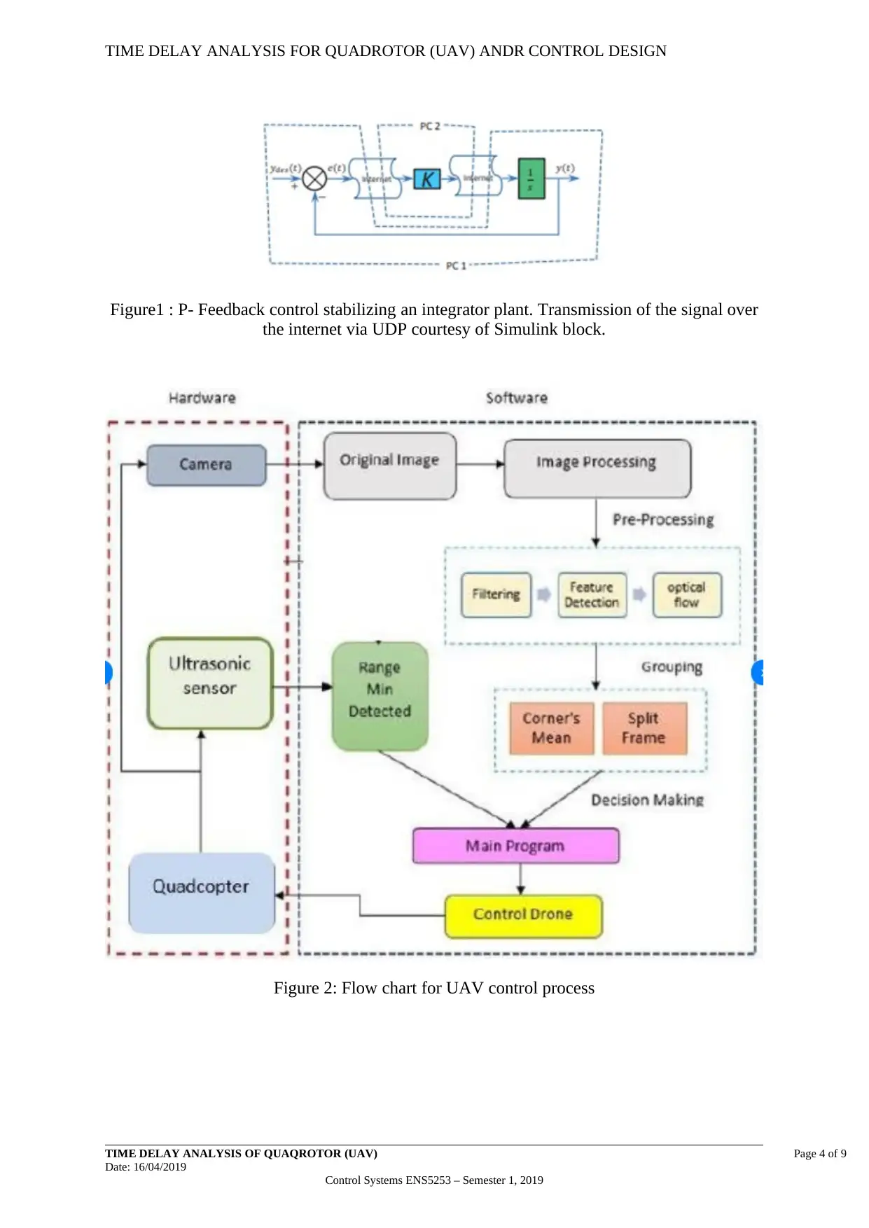
Figure1 : P- Feedback control stabilizing an integrator plant. Transmission of the signal over
the internet via UDP courtesy of Simulink block.
Figure 2: Flow chart for UAV control process
TIME DELAY ANALYSIS OF QUAQROTOR (UAV) Page 4 of 9
Date: 16/04/2019
Control Systems ENS5253 – Semester 1, 2019
Figure1 : P- Feedback control stabilizing an integrator plant. Transmission of the signal over
the internet via UDP courtesy of Simulink block.
Figure 2: Flow chart for UAV control process
TIME DELAY ANALYSIS OF QUAQROTOR (UAV) Page 4 of 9
Date: 16/04/2019
Control Systems ENS5253 – Semester 1, 2019
Paraphrase This Document
Need a fresh take? Get an instant paraphrase of this document with our AI Paraphraser
TIME DELAY ANALYSIS FOR QUADROTOR (UAV) ANDR CONTROL DESIGN
5.0 Conclusion
This research has shown the analytical solutions of DDEs and ODE are used for
estimation of time delay feedback control in internet based as well as quadrotor kind of the
UAVs. By numerical and analytical approaches, the estimation of time delay was as 0.38s
and 0.37s for a quadrotor respectively. The appropriate P controller was applied also the gain
that can reduce the impact of control signal applied saturation on response of the system was
chosen. (Lozano, 2013) The design of the PV controller is for transient response
improvement basing on rightmost roots. MATLAB and Simulink were used in simulating the
estimation value.
TIME DELAY ANALYSIS OF QUAQROTOR (UAV) Page 5 of 9
Date: 16/04/2019
Control Systems ENS5253 – Semester 1, 2019
TIME DELAY ANALYSIS FOR QUADROTOR (UAV) ANDR CONTROL DESIGN
References
Alaimo, S. (2013). Novel Haptic Cues for UAV Tele-Operation. Berlin: Logos Verlag Berlin.
Angelov, P. (2012). Sense and Avoid in UAS: Research and Applications. Susex: Wiley and Sons.
Attaway, S. (2012). Matlab: A Practical Introduction to Programming and Problem Solving. Boston:
Elsevier.
Carey, B. (2016). Enter the Drones: The FAA and UAVs in America. New york: Schiffer Publishing,
Limited.
Daras, N. J. (2010). Applications of Mathematics and Informatics in Science and Engineering. London:
Springer.
Faust, D. R. (2016). Civilian Drones. New York: Power Kids Press.
Leite, E. P. (2010). Matlab - Modelling, Programming and Simulations. Rijika: Scuyo.
Lozano, R. (2013). Unmanned Aerial Vehicles: Embedded Control. London: John Wiley and Sons.
Randal W. Beard, T. W. (2012). Small Unmanned Aircraft: Theory and Practice. Oxford: Princeton
University Press.
Rupprecht, J. (2015). Drones: Their Many Civilian Uses and the U.S. Laws Surrounding Them. Florida:
CreateSpace Independent Publishing Platform, 2015.
TIME DELAY ANALYSIS OF QUAQROTOR (UAV) Page 6 of 9
Date: 16/04/2019
Control Systems ENS5253 – Semester 1, 2019
⊘ This is a preview!⊘
Do you want full access?
Subscribe today to unlock all pages.

Trusted by 1+ million students worldwide

TIME DELAY ANALYSIS FOR QUADROTOR (UAV) ANDR CONTROL DESIGN
Appendix 1: Time Delay Using Characteristic Roots
For ODEs, the technic of estimation using logarithmic decrement gives an
effective method of estimating damping ratio, is given in ζ and ω by:
ζ and ω are obtained from response of transient.
From the second ODEs, (M%) maximum offshoot percentile is related to, by:
The dominant roots for stable system, it lies on the left hand complex plane,
therefore ζ is gotten as
TIME DELAY ANALYSIS OF QUAQROTOR (UAV) Page 7 of 9
Date: 16/04/2019
Control Systems ENS5253 – Semester 1, 2019
Paraphrase This Document
Need a fresh take? Get an instant paraphrase of this document with our AI Paraphraser
TIME DELAY ANALYSIS FOR QUADROTOR (UAV) ANDR CONTROL DESIGN
Appendix 2 : Solve the following Control system Question
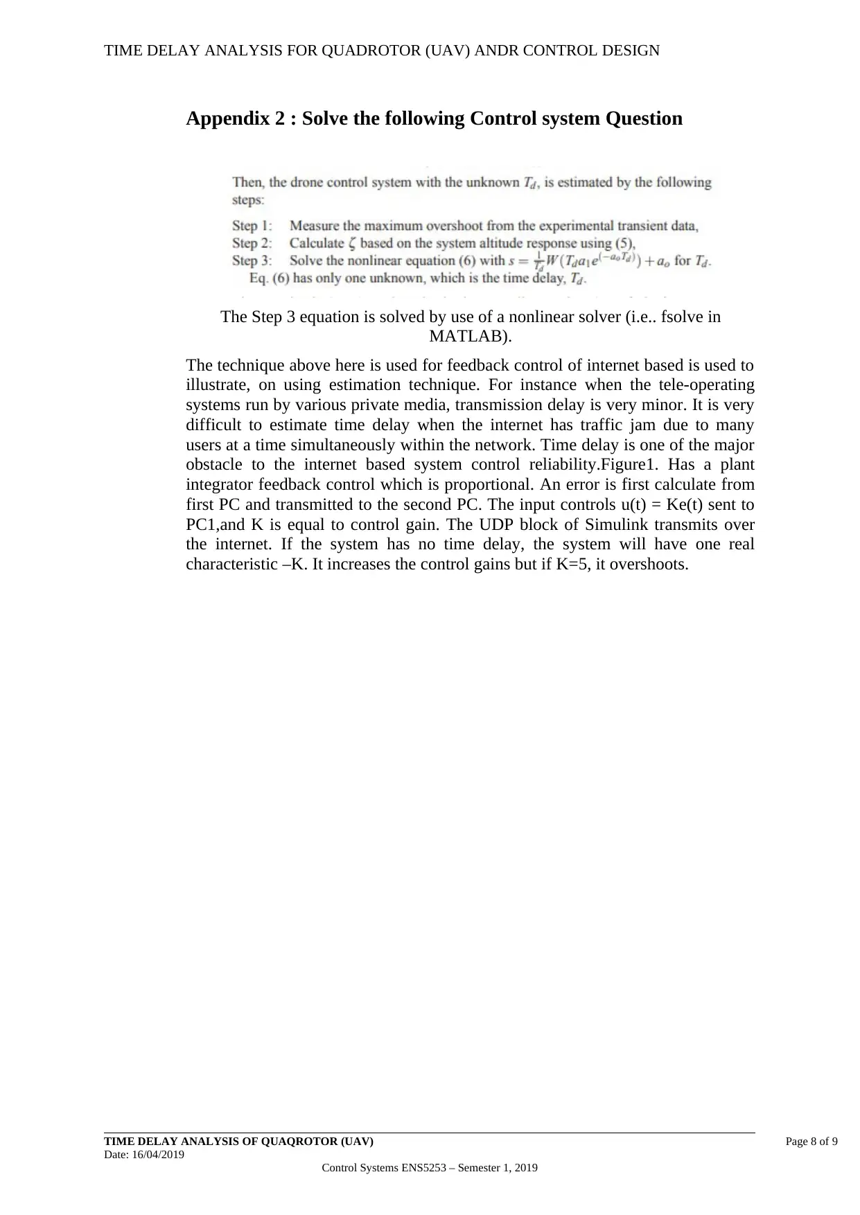
The Step 3 equation is solved by use of a nonlinear solver (i.e.. fsolve in
MATLAB).
The technique above here is used for feedback control of internet based is used to
illustrate, on using estimation technique. For instance when the tele-operating
systems run by various private media, transmission delay is very minor. It is very
difficult to estimate time delay when the internet has traffic jam due to many
users at a time simultaneously within the network. Time delay is one of the major
obstacle to the internet based system control reliability.Figure1. Has a plant
integrator feedback control which is proportional. An error is first calculate from
first PC and transmitted to the second PC. The input controls u(t) = Ke(t) sent to
PC1,and K is equal to control gain. The UDP block of Simulink transmits over
the internet. If the system has no time delay, the system will have one real
characteristic –K. It increases the control gains but if K=5, it overshoots.
TIME DELAY ANALYSIS OF QUAQROTOR (UAV) Page 8 of 9
Date: 16/04/2019
Control Systems ENS5253 – Semester 1, 2019
TIME DELAY ANALYSIS FOR QUADROTOR (UAV) ANDR CONTROL DESIGN
Appendix 3: Estimation of Time delay in relationship with Altitude
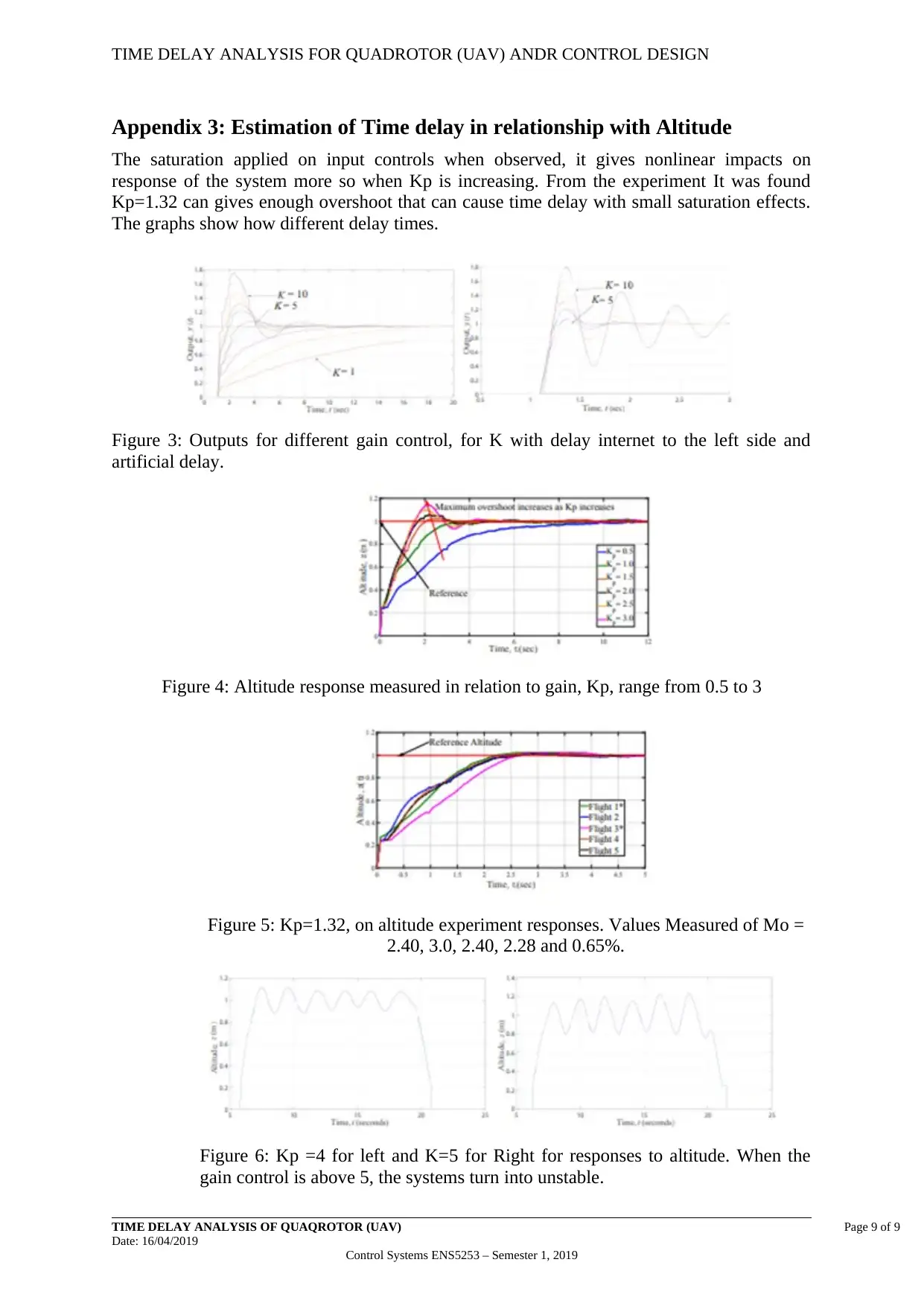
The saturation applied on input controls when observed, it gives nonlinear impacts on
response of the system more so when Kp is increasing. From the experiment It was found
Kp=1.32 can gives enough overshoot that can cause time delay with small saturation effects.
The graphs show how different delay times.
Figure 3: Outputs for different gain control, for K with delay internet to the left side and
artificial delay.
Figure 4: Altitude response measured in relation to gain, Kp, range from 0.5 to 3
Figure 5: Kp=1.32, on altitude experiment responses. Values Measured of Mo =
2.40, 3.0, 2.40, 2.28 and 0.65%.
Figure 6: Kp =4 for left and K=5 for Right for responses to altitude. When the
gain control is above 5, the systems turn into unstable.
TIME DELAY ANALYSIS OF QUAQROTOR (UAV) Page 9 of 9
Date: 16/04/2019
Control Systems ENS5253 – Semester 1, 2019
⊘ This is a preview!⊘
Do you want full access?
Subscribe today to unlock all pages.

Trusted by 1+ million students worldwide
1 out of 9
Related Documents
Your All-in-One AI-Powered Toolkit for Academic Success.
+13062052269
info@desklib.com
Available 24*7 on WhatsApp / Email
![[object Object]](/_next/static/media/star-bottom.7253800d.svg)
Unlock your academic potential
Copyright © 2020–2025 A2Z Services. All Rights Reserved. Developed and managed by ZUCOL.


