Microwave Radio System: RSL and Passive Repeater Analysis

Verified

Added on  2022/11/14

|7
|584
|182
Homework Assignment
AI Summary
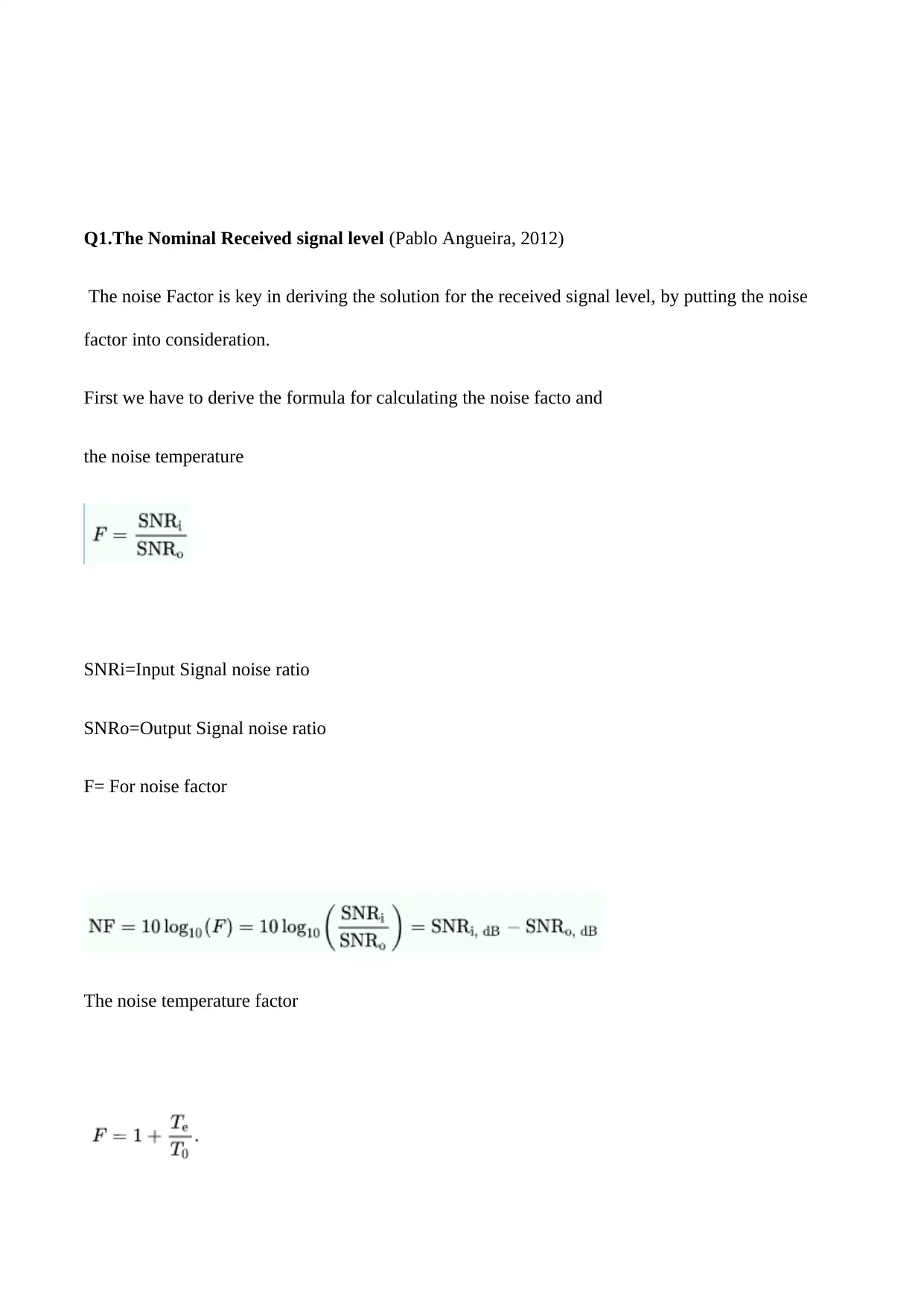
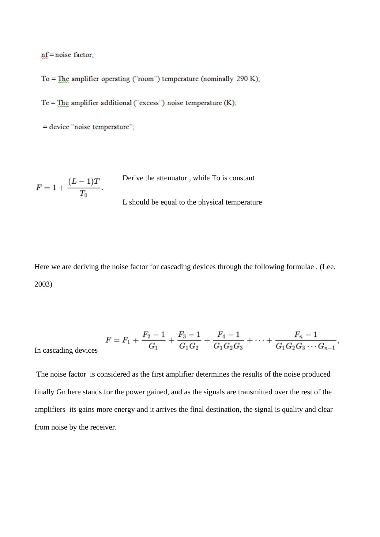
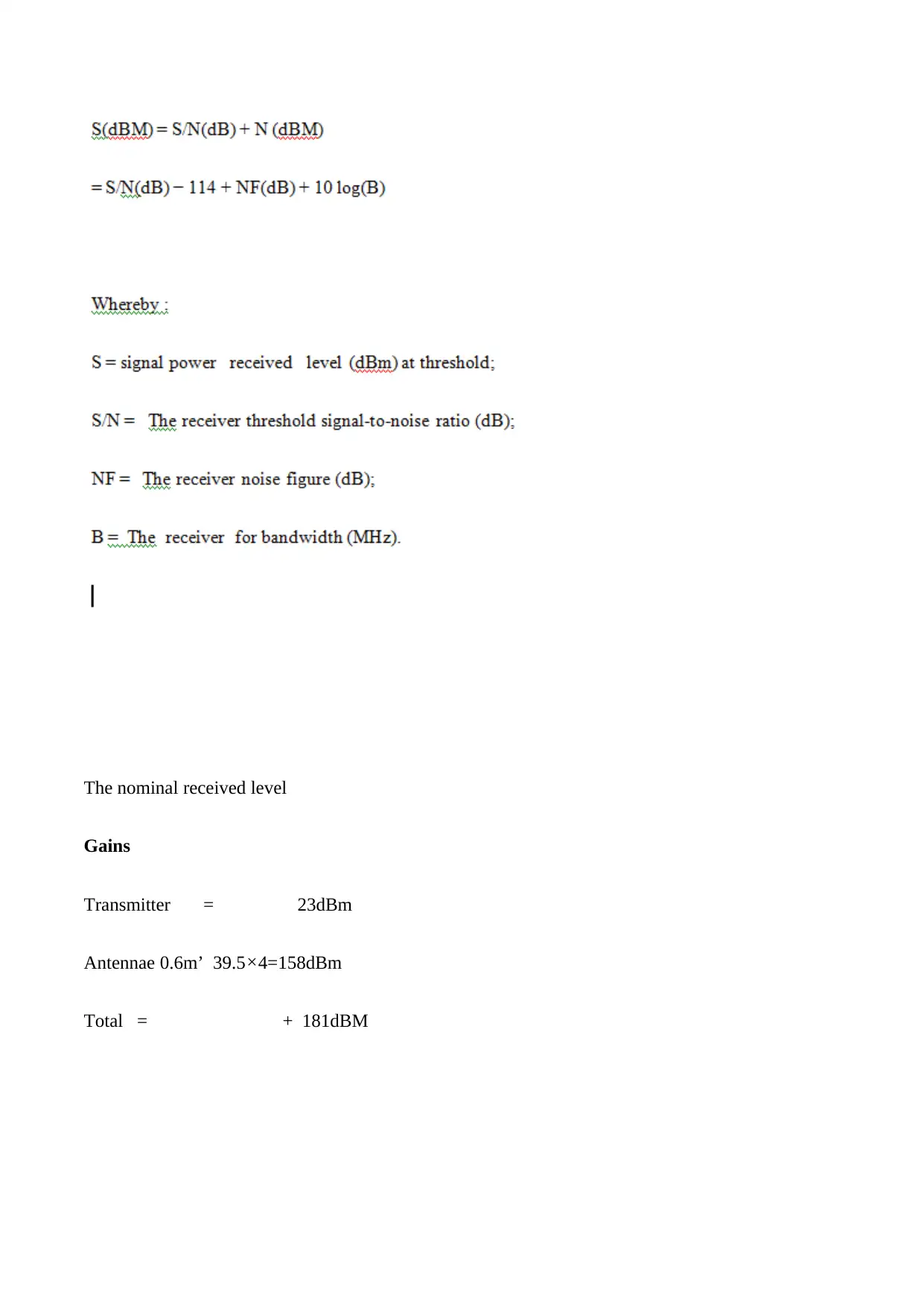
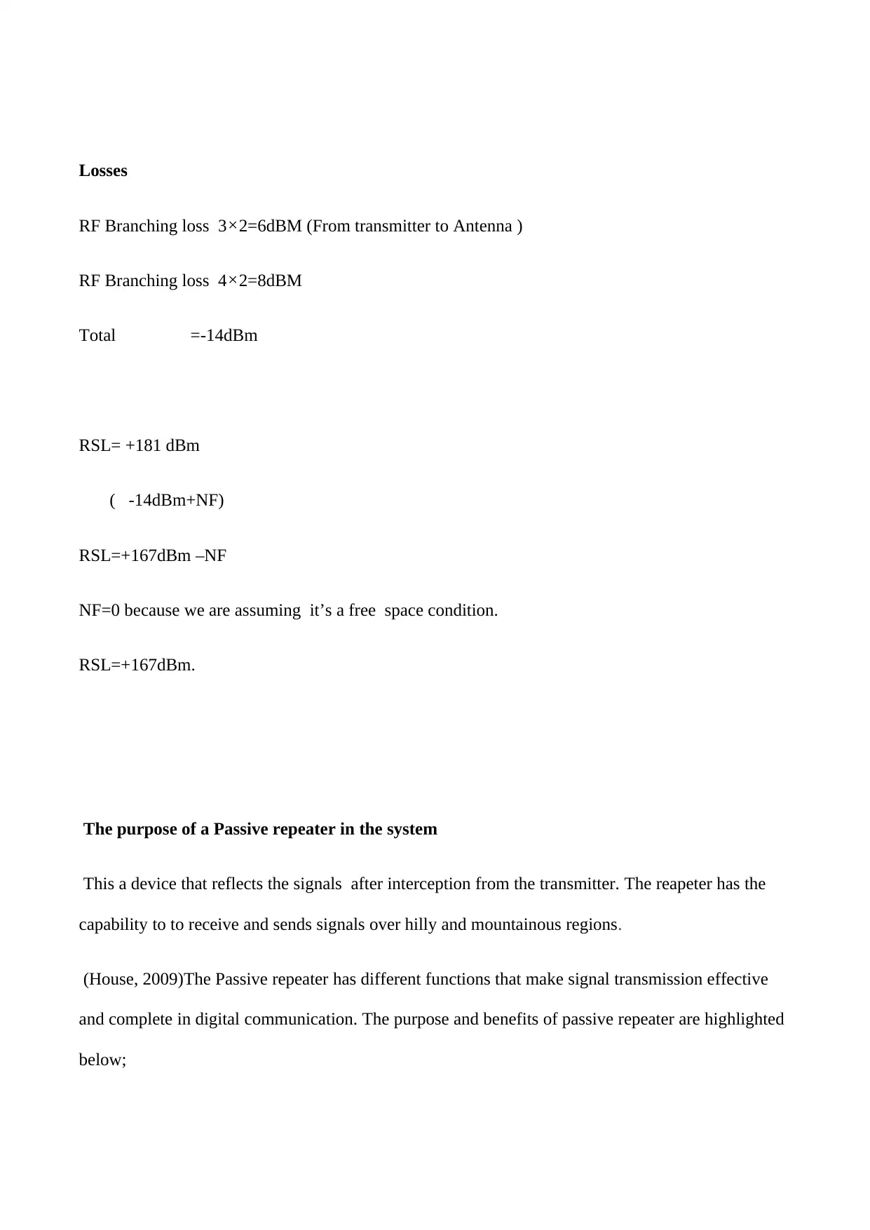
This assignment solution addresses a digital microwave radio system operating in the 18GHz band, providing 2x2 Mbps transmission between two sites and employing a passive repeater. The solution begins by calculating the nominal Received Signal Level (RSL) at the receiver input in dBm, considering the transmitter output power, RF branching losses, and antenna parameters, under free space conditions. The calculation incorporates the noise factor and temperature to derive the formula for received signal level. Subsequently, the solution provides a discussion on the purpose of the passive repeater in this system, highlighting its function in reflecting signals, enabling communication over challenging terrains, and improving signal quality by mitigating noise. The solution also provides the benefits of passive repeaters, such as cost-effectiveness, noise reduction, and their ability to receive and transmit signals in multiple directions. The document concludes with a list of cited references.
Document Page
Student’s name
Instructor’ name
Course Title
21st may 2019
tabler-icon-diamond-filled.svg

Paraphrase This Document

Need a fresh take? Get an instant paraphrase of this document with our AI Paraphraser
Document Page
Q1.The Nominal Received signal level (Pablo Angueira, 2012)
The noise Factor is key in deriving the solution for the received signal level, by putting the noise
factor into consideration.
First we have to derive the formula for calculating the noise facto and
the noise temperature
SNRi=Input Signal noise ratio
SNRo=Output Signal noise ratio
F= For noise factor
The noise temperature factor
Document Page
Derive the attenuator , while To is constant
L should be equal to the physical temperature
Here we are deriving the noise factor for cascading devices through the following formulae , (Lee,
2003)
In cascading devices
The noise factor is considered as the first amplifier determines the results of the noise produced
finally Gn here stands for the power gained, and as the signals are transmitted over the rest of the
amplifiers its gains more energy and it arrives the final destination, the signal is quality and clear
from noise by the receiver.
Document Page
The nominal received level
Gains
Transmitter = 23dBm
Antennae 0.6m’ 39.5×4=158dBm
Total = + 181dBM
tabler-icon-diamond-filled.svg

Paraphrase This Document

Need a fresh take? Get an instant paraphrase of this document with our AI Paraphraser
Document Page
Losses
RF Branching loss 3×2=6dBM (From transmitter to Antenna )
RF Branching loss 4×2=8dBM
Total =-14dBm
RSL= +181 dBm
( -14dBm+NF)
RSL=+167dBm –NF
NF=0 because we are assuming it’s a free space condition.
RSL=+167dBm.
The purpose of a Passive repeater in the system
This a device that reflects the signals after interception from the transmitter. The reapeter has the
capability to to receive and sends signals over hilly and mountainous regions.
(House, 2009)The Passive repeater has different functions that make signal transmission effective
and complete in digital communication. The purpose and benefits of passive repeater are highlighted
below;
Document Page
Proper use of the tall towers to all types of landscapes. The repeater can be erected where in a hilly
and mountainous regions, instead of installing towers to place the repeaters, it is cost effective to
place them on these hilly regions and raised grounds.
The repeaters enable get rid of unnecessary noise, where the signal that was originally transmitted
has been distorted , the repeater can bring it together and restore the information to the original
transmitted signal . (Stallings, 1988)
A repeater has a radio receiver that, the signal produced by the transmitter is usually on a frequency
that is different from the signal received these enabling the receiver from being disabled. In these
respect he repeaters placed on tall building can enable can make performance of communication
better even long distances.
The repeaters’ are designed in a way that the noise produced internally along the circuit is totally
minimized. This enables clear digital signals are received by the receiver.
The repeaters are used to receive and transmit signals in many different regions and directions since
they are commonly used for commercial radio operations.
References
Works Cited
House, A. (2009). Microwave Radio Transmission Design Guide. Trevor Manning .
Lee, T. H. (2003). The Design of CMOS Radio-Frequency Integrated Circuits. Cambridge University Press.
Pablo Angueira, J. R. (2012). Microwave Line of Sight Link Engineering. John Wiley & Sons.
Stallings, W. (1988). Data and computer communications. Macmillan Pub. Co.
Document Page
chevron_up_icon
1 out of 7
circle_padding
hide_on_mobile
zoom_out_icon
[object Object]