ELEC41010 Module: Different Communication Channels and Modeling
VerifiedAdded on 2023/01/23
|13
|2782
|56
Report
AI Summary
This report, prepared for the ELEC41010 module on Professional Development & Engineering Applications, provides a comprehensive overview of different communication channels and system modeling. It begins with an abstract summarizing the research on various communication media, including their advantages and disadvantages, along with discussions on channel losses, noise, interference, and signal distortion, and methods to minimize these effects. The report then delves into the technical aspects of both guided (wired) and unguided (wireless) communication media. Guided media include twisted pair cables (UTP and STP), coaxial cables, and fiber optic cables, with detailed explanations of their components, advantages, and disadvantages. Unguided media encompass satellite microwave, terrestrial microwave transmission, and radio broadcast, including their operational characteristics and limitations. The report also addresses the concepts of noise and distortion in communication systems. The report is well-structured, supported by figures and tables, and concludes by summarizing the key findings and implications of the research.
STUDENT’S NAME/NUMBER:
AWARD: LEVEL 4
MODULE TITLE: Profession Development & Engineering
Applications.
MODULE CODE: ELEC41010.
MODULE TUTOR: Abdel Hamid Salima.
SUBMISSION DATE: 15th May 2019.
1
AWARD: LEVEL 4
MODULE TITLE: Profession Development & Engineering
Applications.
MODULE CODE: ELEC41010.
MODULE TUTOR: Abdel Hamid Salima.
SUBMISSION DATE: 15th May 2019.
1
Paraphrase This Document
Need a fresh take? Get an instant paraphrase of this document with our AI Paraphraser
TITLE
DIFFERENT COMMUNICATION CHANNELS
AND MODELLING OF DIFFERENT
COMMUNICATION SYSTEMS.
2
DIFFERENT COMMUNICATION CHANNELS
AND MODELLING OF DIFFERENT
COMMUNICATION SYSTEMS.
2
Abstract
The aim of this research is to develop an in depth understanding of the technical aspects of
different communication channels and to enhance my skills in modelling different
communication systems. I researched on different communication media, their advantages
and disadvantages, different channel losses, noise, interference and signal distortion. I also
researched on various ways to minimise or eliminate these effects on the transmitted
signals.
In my findings, I found that there is different ways to minimise the effects of noise in
different communication media. In case of twisted pair cable I find the increasing the
number of turns per foot is one of the ways to minimise the effect of noise on the
transmitted signal. The metal foil in the shielded twisted pair cable is used as a measure to
minimise the electromagnetic effects on the transmitted signals. In fibre optic cable, there
are various ways to reduce losses. This include use of high quality cables, uses of qualified
connectors, ensuring that there is no light linkage in the joints and ensuring that the
installation is done by expert team. (MacAskill et al., 2013)
I also found that unguided media or the wireless media tend to loss signals as the distance
between receiver and sender gets longer. The signal transmitted over the unguided media
can get affect by weather conditions such as rain and fog. Locations of the antennas also
effect the signal transmission. Therefore the location of this antenna should be free from
obstacles to minimise signal losses. (Choi et al., pp 1-12, 2010)
3
⊘ This is a preview!⊘
Do you want full access?
Subscribe today to unlock all pages.

Trusted by 1+ million students worldwide
Table of Contents
Introduction.......................................................................................................................................5
Different types of transmission media...............................................................................................5
I. Guided (wired) communication media..................................................................................6
Twisted pair cables....................................................................................................................6
Coaxial Cables..........................................................................................................................7
Fibre Optic Cables.....................................................................................................................8
II. Unguided (wireless) communication media........................................................................10
Satellite microwave.................................................................................................................10
Terrestrial microwave transmission........................................................................................11
Radio broadcast.......................................................................................................................11
Noise...............................................................................................................................................12
Distortion........................................................................................................................................12
Conclusion.......................................................................................................................................12
References......................................................................................................................................13
Table of figures
Figure 1 Communication from transmitter through communication media to receiver.....................5
Figure 2 Tree diagram of different types of communication media...................................................5
Figure 3 UTP cables..........................................................................................................................6
Figure 4 STP cables..........................................................................................................................7
Figure 5 Different parts of coaxial cables..........................................................................................7
Figure 6 Different types of coaxial cable connectors........................................................................8
Figure 7 Inner view of fibre optic cable.............................................................................................9
Figure 8 Different types of fibre optic cable connectors....................................................................9
Figure 9 Illustration of satellite setups............................................................................................10
Figure 10 illustration of terrestrial antenna setup.............................................................................11
4
Paraphrase This Document
Need a fresh take? Get an instant paraphrase of this document with our AI Paraphraser
Introduction
Communication being a sensitive factor in every organization, there is a need to get a
better understanding of various communication channels and simulation of these different
communication systems. Communication is the flow of information within an organization
and other parties that may have effects on the organization.
Communication channel also referred to as transmission media or communication media is
a pathway over which communication can be conveyed from a transmitter to a receiver.
Figure 1 Communication from transmitter through communication media to receiver
Transmission of data occurs in form of either digital signal or analog signals. In analog
signal transmission, the data being transmitted is measured using bandwidth which is the
amount of information transmitted over the channel at a given period of time. Usually is
presented in hertz (Hz). Analog signals being continuous waveforms are usually used to
transmit data such as sound and videos.
On the other hand, digital signal transmission is measured in bandwidth which is the
measure of the bits transmitted per second (bps).
Different types of transmission media.
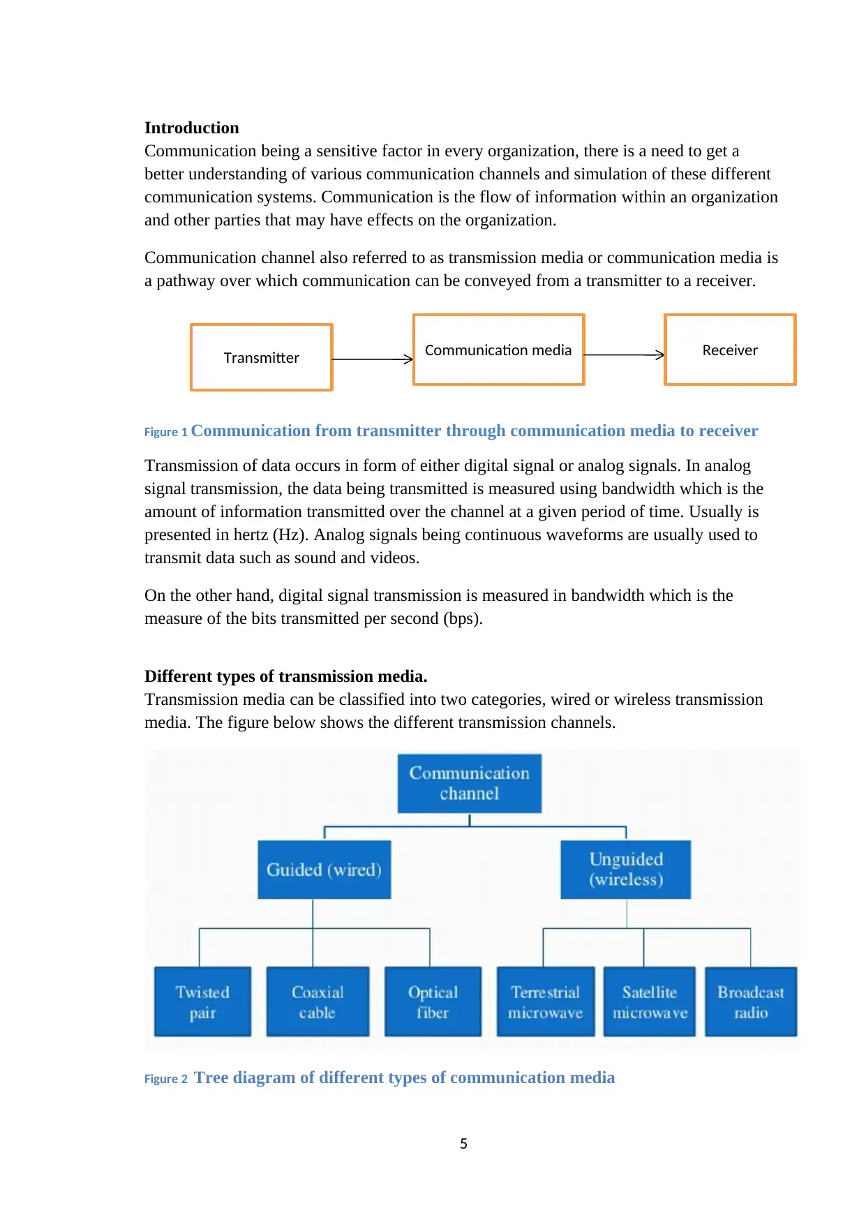
Transmission media can be classified into two categories, wired or wireless transmission
media. The figure below shows the different transmission channels.
Figure 2 Tree diagram of different types of communication media
5
Transmitter Communication media Receiver
I. Guided (wired) communication media
In wired communication media, the communication devices are directly connected using
physical wires/cables. This communication media is usually suitable for local area network
(LAN). The guided communication media includes, twisted pair cables, fibre optic cables,
coaxial cables, communication satellites and terrestrial stations.
Twisted pair cables
Twisted pair is a physical communication media that consist of two wires physically
twisted together. This type of communication media is usually cheaper and easy to install
compared to other communication media. Twisted pair cables consist of two conductors
which contains different plastic insulator twisted together. The frequency of this media
ranges from 0 to 3.5 kHz. One of these conductors carries a signal to a receiver, the other
one is a ground reference. The noise that is present in transmission can be minimised by
increasing the number of twists per foot. Here are the two types of twisted pair cables, STP
and UTP.
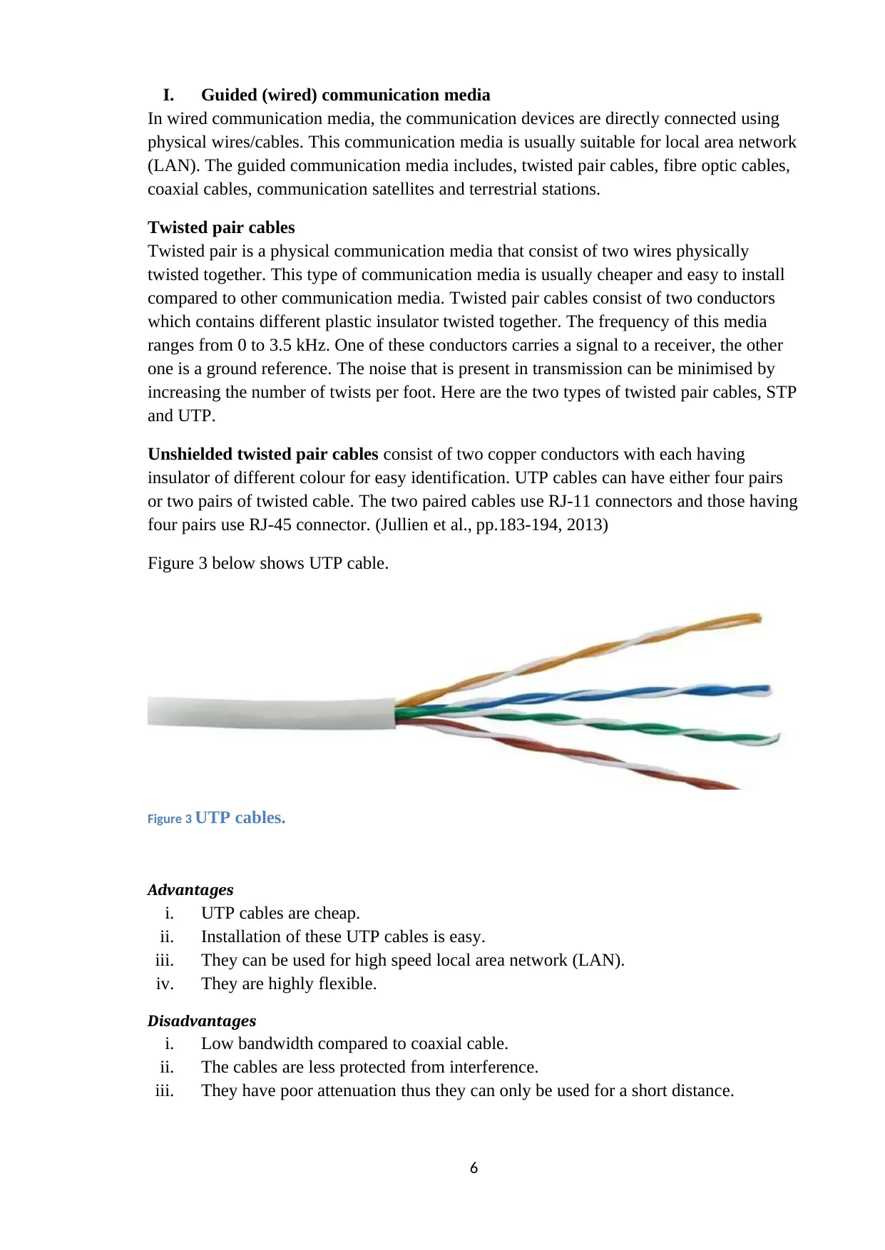
Unshielded twisted pair cables consist of two copper conductors with each having
insulator of different colour for easy identification. UTP cables can have either four pairs
or two pairs of twisted cable. The two paired cables use RJ-11 connectors and those having
four pairs use RJ-45 connector. (Jullien et al., pp.183-194, 2013)
Figure 3 below shows UTP cable.
Figure 3 UTP cables.
Advantages
i. UTP cables are cheap.
ii. Installation of these UTP cables is easy.
iii. They can be used for high speed local area network (LAN).
iv. They are highly flexible.
Disadvantages
i. Low bandwidth compared to coaxial cable.
ii. The cables are less protected from interference.
iii. They have poor attenuation thus they can only be used for a short distance.
6
⊘ This is a preview!⊘
Do you want full access?
Subscribe today to unlock all pages.

Trusted by 1+ million students worldwide
Shielded twisted pair cables have metal foil or braided-mesh that covers the insulated
copper conductor. These metal foils are used to prevent the electromagnetic noise
penetration. These STP cables are faster and expensive compared to unshielded and
coaxial cables. (Vaupotic, 2010)
The figure below show a shielded twisted pair cables.
Figure 4 STP cables
Advantages
i. Installation of this cable is easy.
ii. It can be used to transmit digital or analog signals.
iii. These cables eliminate the crosstalk.
iv. These cables have high attenuation compared to unshielded cables.
Disadvantages
i. STP cables are expensive compared to UTP cables.
ii. STP cables are difficult to manufacture.
iii. STP cables are heavy thus making it more expensive to transport.
Coaxial Cables
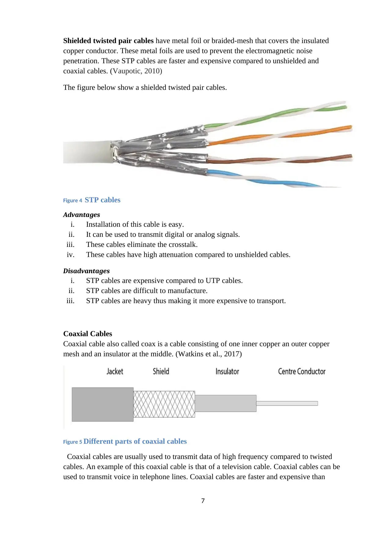
Coaxial cable also called coax is a cable consisting of one inner copper an outer copper
mesh and an insulator at the middle. (Watkins et al., 2017)
Figure 5 Different parts of coaxial cables
Coaxial cables are usually used to transmit data of high frequency compared to twisted
cables. An example of this coaxial cable is that of a television cable. Coaxial cables can be
used to transmit voice in telephone lines. Coaxial cables are faster and expensive than
7
Paraphrase This Document
Need a fresh take? Get an instant paraphrase of this document with our AI Paraphraser
twisted cables pair.Categorization of Coaxial cables is done according their Radio
Government (RG).
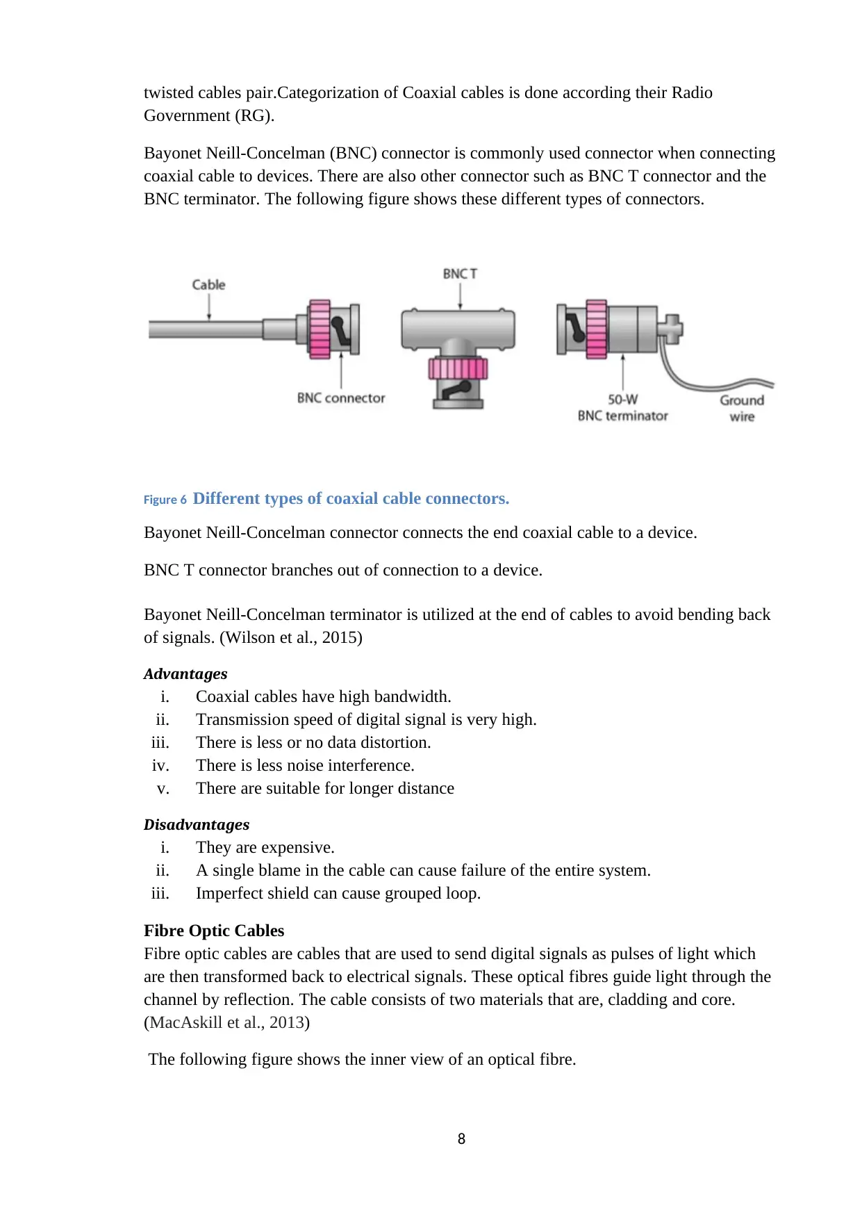
Bayonet Neill-Concelman (BNC) connector is commonly used connector when connecting
coaxial cable to devices. There are also other connector such as BNC T connector and the
BNC terminator. The following figure shows these different types of connectors.
Figure 6 Different types of coaxial cable connectors.
Bayonet Neill-Concelman connector connects the end coaxial cable to a device.
BNC T connector branches out of connection to a device.
Bayonet Neill-Concelman terminator is utilized at the end of cables to avoid bending back
of signals. (Wilson et al., 2015)
Advantages
i. Coaxial cables have high bandwidth.
ii. Transmission speed of digital signal is very high.
iii. There is less or no data distortion.
iv. There is less noise interference.
v. There are suitable for longer distance
Disadvantages
i. They are expensive.
ii. A single blame in the cable can cause failure of the entire system.
iii. Imperfect shield can cause grouped loop.
Fibre Optic Cables
Fibre optic cables are cables that are used to send digital signals as pulses of light which
are then transformed back to electrical signals. These optical fibres guide light through the
channel by reflection. The cable consists of two materials that are, cladding and core.
(MacAskill et al., 2013)
The following figure shows the inner view of an optical fibre.
8
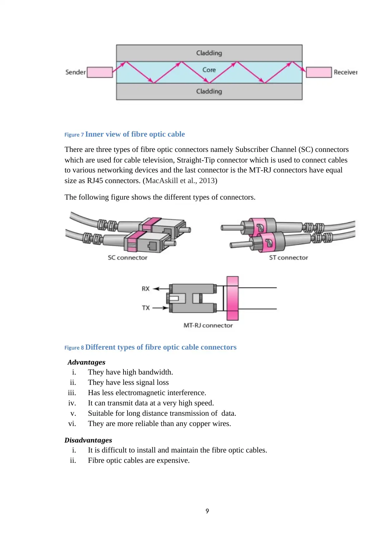
Figure 7 Inner view of fibre optic cable
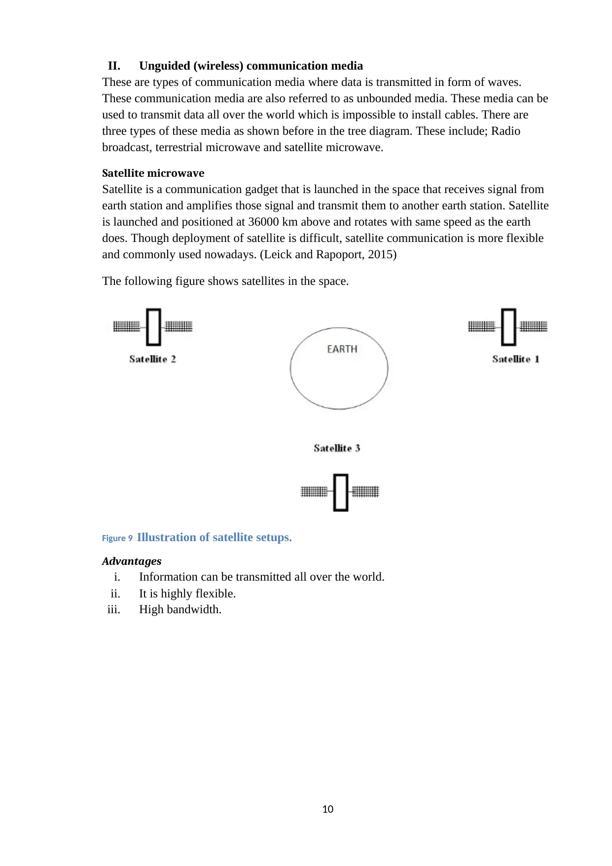
There are three types of fibre optic connectors namely Subscriber Channel (SC) connectors
which are used for cable television, Straight-Tip connector which is used to connect cables
to various networking devices and the last connector is the MT-RJ connectors have equal
size as RJ45 connectors. (MacAskill et al., 2013)
The following figure shows the different types of connectors.
Figure 8 Different types of fibre optic cable connectors
Advantages
i. They have high bandwidth.
ii. They have less signal loss
iii. Has less electromagnetic interference.
iv. It can transmit data at a very high speed.
v. Suitable for long distance transmission of data.
vi. They are more reliable than any copper wires.
Disadvantages
i. It is difficult to install and maintain the fibre optic cables.
ii. Fibre optic cables are expensive.
9
⊘ This is a preview!⊘
Do you want full access?
Subscribe today to unlock all pages.

Trusted by 1+ million students worldwide
II. Unguided (wireless) communication media
These are types of communication media where data is transmitted in form of waves.
These communication media are also referred to as unbounded media. These media can be
used to transmit data all over the world which is impossible to install cables. There are
three types of these media as shown before in the tree diagram. These include; Radio
broadcast, terrestrial microwave and satellite microwave.
Satellite microwave
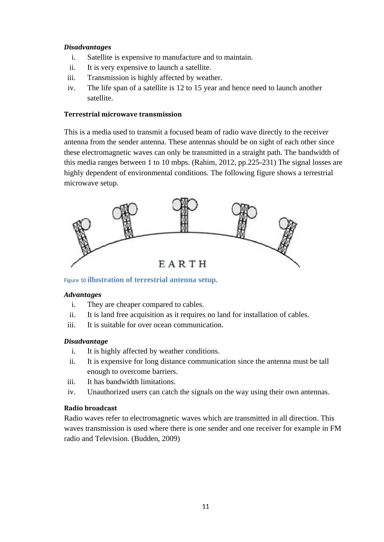
Satellite is a communication gadget that is launched in the space that receives signal from
earth station and amplifies those signal and transmit them to another earth station. Satellite
is launched and positioned at 36000 km above and rotates with same speed as the earth
does. Though deployment of satellite is difficult, satellite communication is more flexible
and commonly used nowadays. (Leick and Rapoport, 2015)
The following figure shows satellites in the space.
Figure 9 Illustration of satellite setups.
Advantages
i. Information can be transmitted all over the world.
ii. It is highly flexible.
iii. High bandwidth.
10
Paraphrase This Document
Need a fresh take? Get an instant paraphrase of this document with our AI Paraphraser
Disadvantages
i. Satellite is expensive to manufacture and to maintain.
ii. It is very expensive to launch a satellite.
iii. Transmission is highly affected by weather.
iv. The life span of a satellite is 12 to 15 year and hence need to launch another
satellite.
Terrestrial microwave transmission
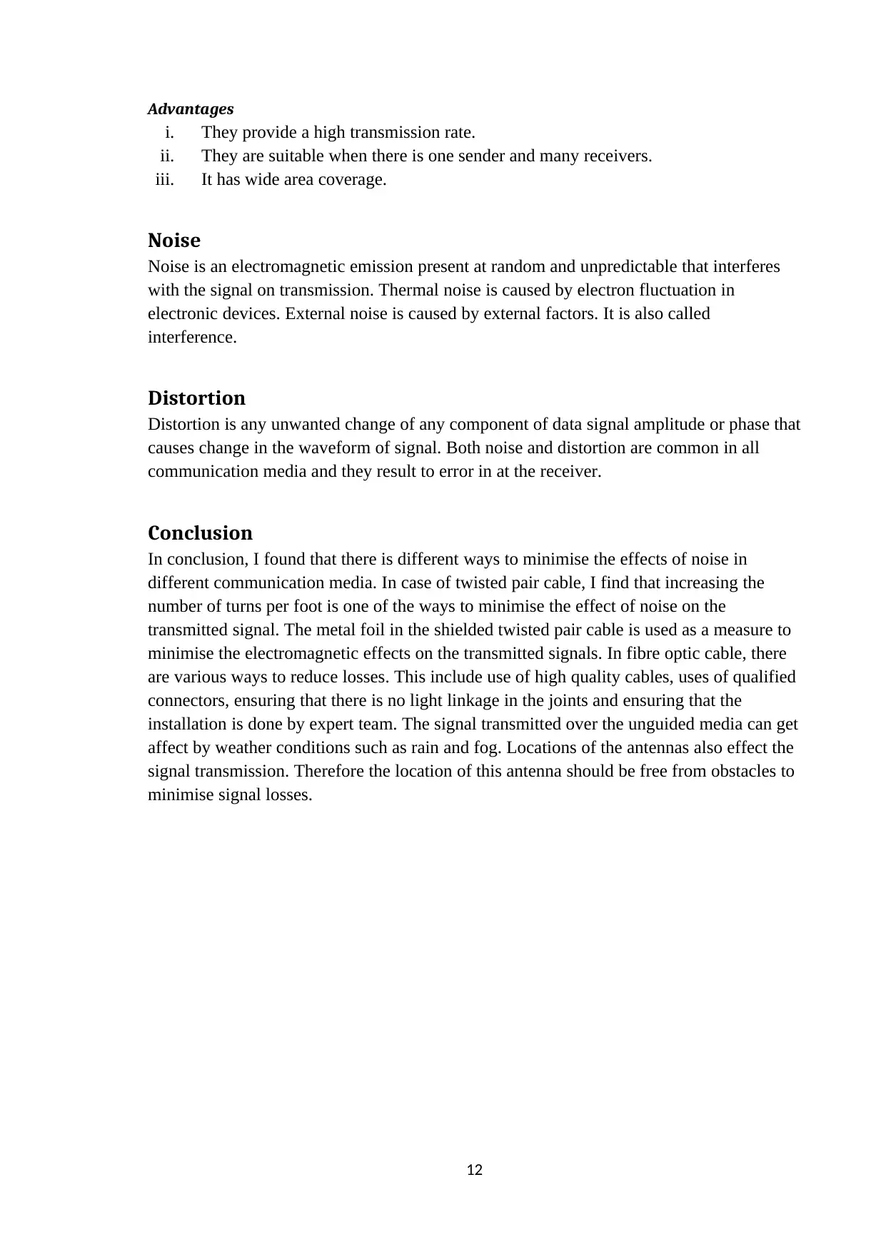
This is a media used to transmit a focused beam of radio wave directly to the receiver
antenna from the sender antenna. These antennas should be on sight of each other since
these electromagnetic waves can only be transmitted in a straight path. The bandwidth of
this media ranges between 1 to 10 mbps. (Rahim, 2012, pp.225-231) The signal losses are
highly dependent of environmental conditions. The following figure shows a terrestrial
microwave setup.
Figure 10 illustration of terrestrial antenna setup.
Advantages
i. They are cheaper compared to cables.
ii. It is land free acquisition as it requires no land for installation of cables.
iii. It is suitable for over ocean communication.
Disadvantage
i. It is highly affected by weather conditions.
ii. It is expensive for long distance communication since the antenna must be tall
enough to overcome barriers.
iii. It has bandwidth limitations.
iv. Unauthorized users can catch the signals on the way using their own antennas.
Radio broadcast
Radio waves refer to electromagnetic waves which are transmitted in all direction. This
waves transmission is used where there is one sender and one receiver for example in FM
radio and Television. (Budden, 2009)
11
Advantages
i. They provide a high transmission rate.
ii. They are suitable when there is one sender and many receivers.
iii. It has wide area coverage.
Noise
Noise is an electromagnetic emission present at random and unpredictable that interferes
with the signal on transmission. Thermal noise is caused by electron fluctuation in
electronic devices. External noise is caused by external factors. It is also called
interference.
Distortion
Distortion is any unwanted change of any component of data signal amplitude or phase that
causes change in the waveform of signal. Both noise and distortion are common in all
communication media and they result to error in at the receiver.
Conclusion
In conclusion, I found that there is different ways to minimise the effects of noise in
different communication media. In case of twisted pair cable, I find that increasing the
number of turns per foot is one of the ways to minimise the effect of noise on the
transmitted signal. The metal foil in the shielded twisted pair cable is used as a measure to
minimise the electromagnetic effects on the transmitted signals. In fibre optic cable, there
are various ways to reduce losses. This include use of high quality cables, uses of qualified
connectors, ensuring that there is no light linkage in the joints and ensuring that the
installation is done by expert team. The signal transmitted over the unguided media can get
affect by weather conditions such as rain and fog. Locations of the antennas also effect the
signal transmission. Therefore the location of this antenna should be free from obstacles to
minimise signal losses.
12
⊘ This is a preview!⊘
Do you want full access?
Subscribe today to unlock all pages.

Trusted by 1+ million students worldwide
1 out of 13
Related Documents
Your All-in-One AI-Powered Toolkit for Academic Success.
+13062052269
info@desklib.com
Available 24*7 on WhatsApp / Email
![[object Object]](/_next/static/media/star-bottom.7253800d.svg)
Unlock your academic potential
Copyright © 2020–2026 A2Z Services. All Rights Reserved. Developed and managed by ZUCOL.


