A Comprehensive Report on Supercapacitor Technology for Energy Storage
VerifiedAdded on 2020/05/28
sSUPERCAPACITOR AS ENERGY STORAGE DEVICE
By Name
Course
Instructor
Institution
Location
Date
Paraphrase This Document
ABSTRACT
The power generated from the renewable sources of energy like wind is variable in
nature and in most cases it contains unaccepted serious fluctuations of the electrical energy
generated. This serious bottleneck is alleviated by using energy storage device system. And for
so many years battery has been employed to do this storage. Nonetheless, the cost of these
batteries, limited lifespan, and lower storage capacity has been a great concern to them. To help
solve these problems of this battery, a supercapacitor storage device is used (Kularatna, 2014). In
this paper, we will basically discuss on how supercapacitor is employed in the storage of
electrical energy as well as why it is employed in the storage of electrical energy.
This research paper will illustrate how this supercapacitor is employed in on-grid power
generated by solar PV system for the storage. This storage device stores electrical energy for a
relatively long time as compared to the normal battery. Energy obtained from PV panels are
basically irregular sustainable electrical energy hence for a good and continuous supply of
electrical energy supercapacitor which stores more electrical energy will be required (Zhang,
2012). And in the remote areas which area which is far from the national grid a standalone
Photovoltaic system is employed.
These Super Capacitors are connected to the Photovoltaic panels which enable the
storage of electrical energy immediately after the generation (Peng, 2015). This is employed to
avoid the electrical energy which would have been wasted if not used at the point of the
generation. And it also helps to ensure that there is a continuous supply of electrical energy even
during that time with less illumination of radiation ( (Frackowiak, 2013)).
Table of content
Table of content...............................................................................................................................1
ABSTRACT....................................................................................................................................1
INTRODUCTION...........................................................................................................................2
LITERATURE REVIEW................................................................................................................4
Supercapacitor energy system......................................................................................................5
Solar energy design of harvesting system....................................................................................7
The microcontroller selection......................................................................................................7
Energy harvesting circuit.............................................................................................................8
Sepic DC-DC converter...............................................................................................................9
Microcontroller software............................................................................................................10
Power MOSFET selection and gate driver................................................................................11
Supercapacitor energy estimation..............................................................................................11
Supercapacitor overcharging consideration...............................................................................12
Motivation and objective...........................................................................................................12
Innovative contribution..............................................................................................................13
Operation of the Super Capacitor...............................................................................................13
Charging the Super Capacitor storage device............................................................................15
Discharging the Super Capacitor storage device.......................................................................18
Comparison between the supercapacitors and the battery.........................................................20
RELATIVE DATA AND STATISTICS.......................................................................................24
FUTURE ASPECTS OF SUPER CAPACITOR..........................................................................26
CONCLUSION..............................................................................................................................27
REFERENCES..............................................................................................................................29
⊘ This is a preview!⊘
Do you want full access?
Subscribe today to unlock all pages.

Trusted by 1+ million students worldwide
INTRODUCTION
Energy storage system is required to help in the continuous supply of electrical energy
after generation. And since the solar photovoltaic cells produce relatively less electrical energy,
the storage is required to help reduce the power loss which might be realized in the generation
when the electrical energy is not in use (Miller, 2011). This is because the electrical power
demand always fluctuates highly and consequently power stations should be overdesigned which
illustrates expensive and inefficient electrical system. Therefore energy production is made
independent of the demand by this energy storage system. With the presence of large electricity
storage capacity like for the Supercapacitor, the generating capacity could be designed in
electrical average terms as opposed to electrical peak terms (Zhou, 2013).
Subsequently, electrical energy storage system could offer various merits over electrical
peak terms, such advantages may be load following, standby reserve, and peaking power. In
addition, the dangerous emission of the thermal power sources could be highly minimized with
the improved efficiency of operation of the on-grid solar energy generation, thanks to the
electrical energy storage system for providing dispatchable load and spinning reserve (Turpin,
2012). Moreover, electrical energy storage system is a required technology for distributed
energy resource system. A distributed energy resource system is meant to provide a sustainable
and a highly environmental friendly alternative to the traditional energy system (Peng, 2015).
Solar photovoltaic energy conversion mechanism has actually shown a great
improvement in the way people adopt it. This is true due to the fact that the solar energy gives a
free, clean and pollution-free energy. The solar energy also shows a relatively higher efficiency
of operation, the efficiency of the operation of solar PV generation system is further enhanced by
Paraphrase This Document
the incorporation of the Super Capacitor to help in the energy storage (Wang, 2013). For the
standalone system, remote regions are supplied with either AC or DC power with converters and
energy storage devices (Super Capacitor). And on the other hand for the on grid-connected,
generated power supply to the utility services without any electrical energy storage components
which have made added the advantage of this system of about 99% efficient than the standalone
system (Delnick, 2011).
For the grid-connected power PV generating plant, the power generated by the PV plant
is directly by obtained by the transmission line and it is then distributed to the required places
(places of demand). Hereafter the application of these Super Capacitors in the storage of
electrical energy which hence helps in the better operation of the PV power supply (Conway,
2013). Because of the fluctuation of input supply at the side of the inverter, PV inverter
topography and the control design should be done in line with the promising control structure.
The DC voltage link is fixed to the supply constant voltage to the electrical inverter. The Super
Capacitor storage device is employed and connected after the PV modules and depending on the
how the electrical power is demanded the DC AC inverter is employed to help convert the DC
power to AC power (Zhou, 2014).
When a lot of power is demanded then the Super Capacitor storage device is
automatically disconnected by a changeover from the system to avoid storage of any electrical
energy (Ma, 2011). But during those times when the electrical energy is not demanded, the
electrical power is stored in the Super Capacitor and then it will be used during those times when
there is no sunlight like the cloudy days or at night (Engineers, 2011). This will hence promote a
steady flow of electrical energy to the places where the power is demanded regardless of the time
of the day and the nature of weather. And with the usage of the Super Capacitor storage device
instead of the battery makes it so possible to store more electrical energy through storage of
electrical energy at an electrode-electrolyte interface. This interface consists of two plates of
metal that are coated with a porous material commonly known as activated carbon hence they
pose an increase storage area storing much more energy which will help in the supply of
electrical energy of equal amount as the one generated from the PV panels directly (Feaver,
2010).
And this being a renewable and a clean energy, it hence becomes highly accepted to the
society and more electrical energy will be produced for a long time through using this Super
Capacitor storage device (Jelley, 2013). The power from the supercapacitor is in DC form thus if
the appliance is operating on AC then an inverter will be used to convert it from DC to AC form.
But in some cases the appliances may be operating in DC hence there will be no need for the
inverter at that point since the power from PV is in DC form.
LITERATURE REVIEW
Supercapacitor energy system
An efficient and reliable electric power storage system is essentially required in an
industry for electrical power generation scheme and most importantly solar power generation
scheme since it involves a highly fluctuating supply of electrical; power. Originally,
dissemination and transmission of power involve power energy transportation from the source to
the point of consumption in a unidirectional manner. As result of this, electrical power energy
consumption must, therefore, comply with the demand and generation of the electrical energy
⊘ This is a preview!⊘
Do you want full access?
Subscribe today to unlock all pages.

Trusted by 1+ million students worldwide
though, in contradiction, power demand constantly fluctuate leading adjustments in the design of
power plants to meet the inconsistent demands from the consumer (Srinivasan, 2010).
In the recent past, photovoltaic cells became more popular in increasing the independence
of systems which are embedded. The output features and reliability of photovoltaic cells differs
none uniformly in relation to the prevailing environmental conditions which includes
temperature and irradiations (Zheng, 2012). In addition, power obtained or sourced from this cell
dominantly rely on its point of operation for example when demanding sufficient energy
amounts and quantity, it is maintained at its maximum operating point. Photovoltaic terminal
voltage always falls to a negligible value whenever a high current is demanded from it whereas
whenever there is no or limited demand of current from the cell, there is an increase in its
terminal voltage towards the open circuit voltage (Krauter, 2012). In conclusion, there is no
generation of power at both extreme scenarios of the photovoltaic cell hence the urgency for
coming up with an algorithm maintaining the cell at its optimum power point also known as
power point tracking methods.
Production of electrical energy in solar energy plants has been made reliable through use of
supercapacitors as an energy storage system instead of the battery due to its high capability of
storing and efficiently disseminating power when required (Hoffmann, 2015). Due to large-scale
storage capabilities of supercapacitors, generating a quantity of power in average electrical terms
instead peak demand levels. In solving the highly varying and inconsistent source of energy in
solar energy production, batteries are replaced with supercapacitors which facilitate power input
and output cycles in a reduced amount of time of approximately 10 seconds thus charge and
discharge cycles are made inferior (Gevorkian, 2012). Operation of supercapacitors is majorly
Paraphrase This Document
considered when electrical power demands are high and adjustments on the supplied electrical
energy are needed.
Energy is stored in supercapacitors in conformity to two phenomena occurring at within
the electrode and electrolyte interface, namely: electric double layer which enables
supercapacitors store energy through charged layers of ions from the attracted electrolyte to the
surface of the electrode by forces of electrostatic or selective adsorption of ions into the surface
and pseudocapacitance which chemically enables supercapacitors to store energy just as batteries
(Onkari, 2010). When compared to the conventional capacitors, supercapacitors possess greatly
varying features of operation which must be necessarily being looked into whenever a power
system is designed with them.
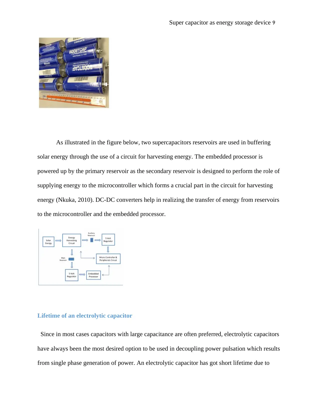
The below figure shows a combination of eight 3000F supercapacitors in series
connection with 2.7v maximum voltage and 21.6v of combined super capacitor block voltage. A
sum of ½ *30008*2.7^2=1000935j of energy is thus stored in a single capacitor and a grand total
of 87840J of stored energy in all the eight block of supercapacitors (Jose, 2012). It is of
importance to note that the estimates of this energy can in companion of errors originating from
charge redistribution. Nevertheless, due to the capability of the supercapacitors to store such high
energy amounts or quantity, more care should be implemented to avoid short-circuiting the
capacitors.
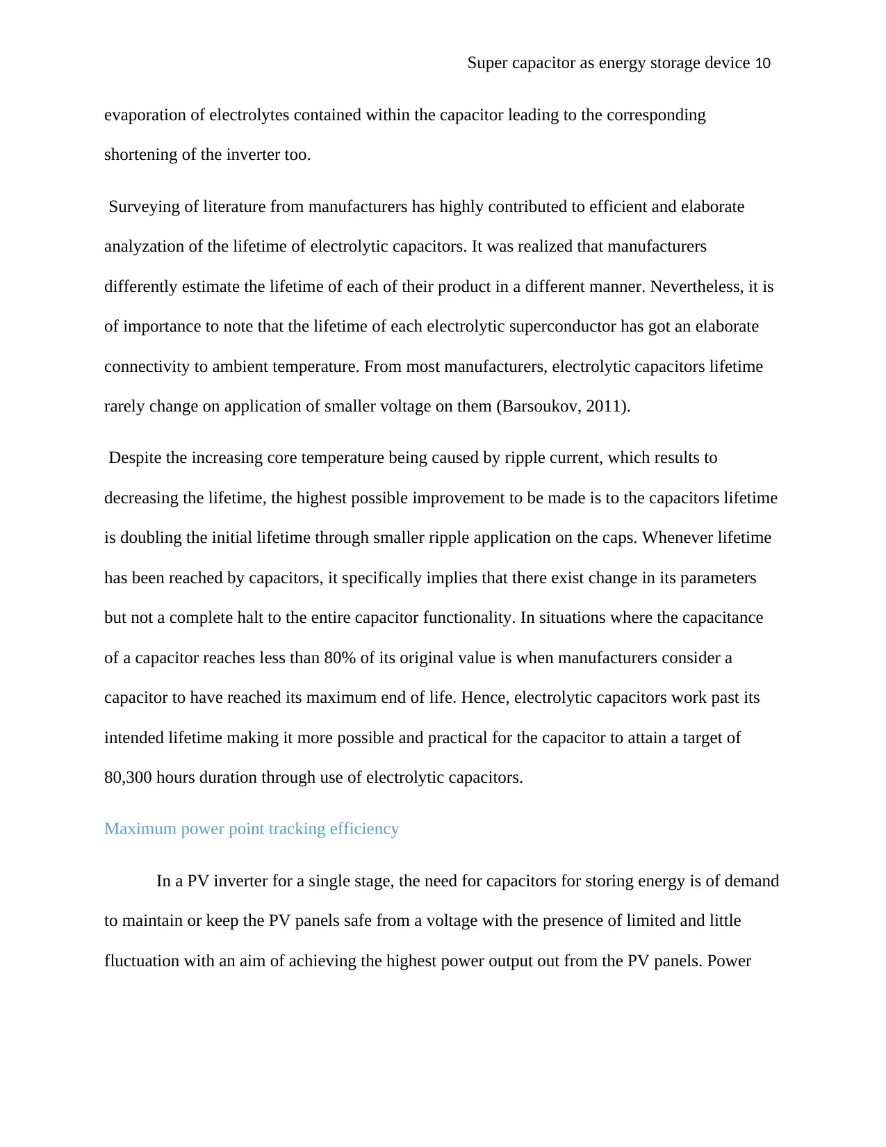
As illustrated in the figure below, two supercapacitors reservoirs are used in buffering
solar energy through the use of a circuit for harvesting energy. The embedded processor is
powered up by the primary reservoir as the secondary reservoir is designed to perform the role of
supplying energy to the microcontroller which forms a crucial part in the circuit for harvesting
energy (Nkuka, 2010). DC-DC converters help in realizing the transfer of energy from reservoirs
to the microcontroller and the embedded processor.
Lifetime of an electrolytic capacitor
Since in most cases capacitors with large capacitance are often preferred, electrolytic capacitors
have always been the most desired option to be used in decoupling power pulsation which results
from single phase generation of power. An electrolytic capacitor has got short lifetime due to
⊘ This is a preview!⊘
Do you want full access?
Subscribe today to unlock all pages.

Trusted by 1+ million students worldwide
evaporation of electrolytes contained within the capacitor leading to the corresponding
shortening of the inverter too.
Surveying of literature from manufacturers has highly contributed to efficient and elaborate
analyzation of the lifetime of electrolytic capacitors. It was realized that manufacturers
differently estimate the lifetime of each of their product in a different manner. Nevertheless, it is
of importance to note that the lifetime of each electrolytic superconductor has got an elaborate
connectivity to ambient temperature. From most manufacturers, electrolytic capacitors lifetime
rarely change on application of smaller voltage on them (Barsoukov, 2011).
Despite the increasing core temperature being caused by ripple current, which results to
decreasing the lifetime, the highest possible improvement to be made is to the capacitors lifetime
is doubling the initial lifetime through smaller ripple application on the caps. Whenever lifetime
has been reached by capacitors, it specifically implies that there exist change in its parameters
but not a complete halt to the entire capacitor functionality. In situations where the capacitance
of a capacitor reaches less than 80% of its original value is when manufacturers consider a
capacitor to have reached its maximum end of life. Hence, electrolytic capacitors work past its
intended lifetime making it more possible and practical for the capacitor to attain a target of
80,300 hours duration through use of electrolytic capacitors.
Maximum power point tracking efficiency
In a PV inverter for a single stage, the need for capacitors for storing energy is of demand
to maintain or keep the PV panels safe from a voltage with the presence of limited and little
fluctuation with an aim of achieving the highest power output out from the PV panels. Power
Paraphrase This Document
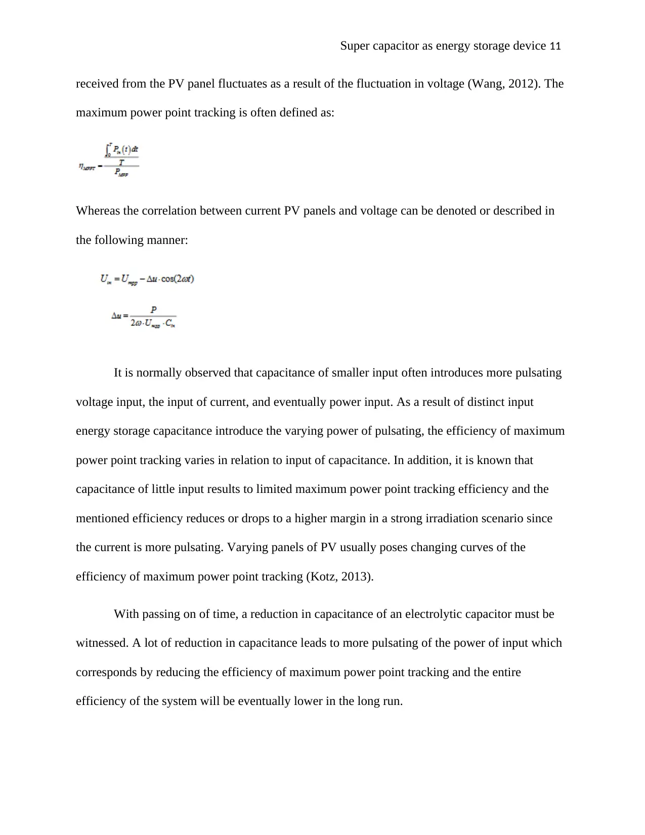
received from the PV panel fluctuates as a result of the fluctuation in voltage (Wang, 2012). The
maximum power point tracking is often defined as:
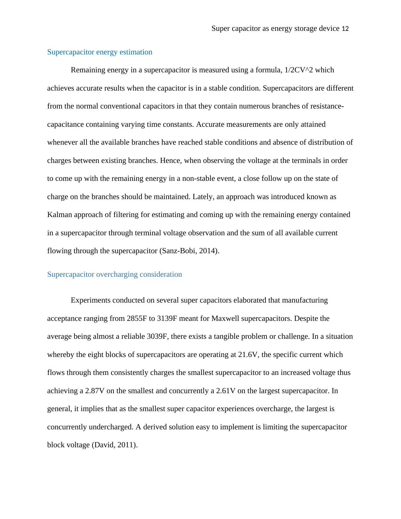
Whereas the correlation between current PV panels and voltage can be denoted or described in
the following manner:
It is normally observed that capacitance of smaller input often introduces more pulsating
voltage input, the input of current, and eventually power input. As a result of distinct input
energy storage capacitance introduce the varying power of pulsating, the efficiency of maximum
power point tracking varies in relation to input of capacitance. In addition, it is known that
capacitance of little input results to limited maximum power point tracking efficiency and the
mentioned efficiency reduces or drops to a higher margin in a strong irradiation scenario since
the current is more pulsating. Varying panels of PV usually poses changing curves of the
efficiency of maximum power point tracking (Kotz, 2013).
With passing on of time, a reduction in capacitance of an electrolytic capacitor must be
witnessed. A lot of reduction in capacitance leads to more pulsating of the power of input which
corresponds by reducing the efficiency of maximum power point tracking and the entire
efficiency of the system will be eventually lower in the long run.
Supercapacitor energy estimation
Remaining energy in a supercapacitor is measured using a formula, 1/2CV^2 which
achieves accurate results when the capacitor is in a stable condition. Supercapacitors are different
from the normal conventional capacitors in that they contain numerous branches of resistance-
capacitance containing varying time constants. Accurate measurements are only attained
whenever all the available branches have reached stable conditions and absence of distribution of
charges between existing branches. Hence, when observing the voltage at the terminals in order
to come up with the remaining energy in a non-stable event, a close follow up on the state of
charge on the branches should be maintained. Lately, an approach was introduced known as
Kalman approach of filtering for estimating and coming up with the remaining energy contained
in a supercapacitor through terminal voltage observation and the sum of all available current
flowing through the supercapacitor (Sanz-Bobi, 2014).
Supercapacitor overcharging consideration
Experiments conducted on several super capacitors elaborated that manufacturing
acceptance ranging from 2855F to 3139F meant for Maxwell supercapacitors. Despite the
average being almost a reliable 3039F, there exists a tangible problem or challenge. In a situation
whereby the eight blocks of supercapacitors are operating at 21.6V, the specific current which
flows through them consistently charges the smallest supercapacitor to an increased voltage thus
achieving a 2.87V on the smallest and concurrently a 2.61V on the largest supercapacitor. In
general, it implies that as the smallest super capacitor experiences overcharge, the largest is
concurrently undercharged. A derived solution easy to implement is limiting the supercapacitor
block voltage (David, 2011).
⊘ This is a preview!⊘
Do you want full access?
Subscribe today to unlock all pages.

Trusted by 1+ million students worldwide
Motivation and objective
In general, batteries containing lead acids are utilized as a conventional idea for
photovoltaic though instead, it suffers effects and disappointments that diminish the life of
batteries and consecutively making the end product cost very expensive. Li-ion batteries were
considered to solve failures experienced by the lead-acid batteries but its performance was also
affected by the batteries life cycle that greatly suffers impacts of voltage drop which is witnessed
during high current discharge. Supercapacitors have therefore resulted in a hybrid energy storage
system which has attempted to solve and reduce failures experienced by the batteries resulting
from high current discharge (Komoto, 2013).
Innovative contribution
The main idea of contribution is coming up with a photovoltaic inverter with a power
capability of residential and large-scale systems of photovoltaic with the capability of handling
and managing solar power injections through storage systems means. Since batteries provide
limited time for storage of power energy, it is of great essentiality to implement utilization of
supercapacitors as a power storage system.
Operation of the Super Capacitor
Even though both the Super Capacitor and the battery do the same job storage of
electrical energy but both operate in different ways (Tagare, 2011). Batteries store electrical
energy in electrochemical form, reaction inside the cell release electrical carriers which form a
functional electric. And for the Super Capacitor operates by storing electrical energy in form of
the electric field which is created when charges of unlike charge that is positive and negative) are
Paraphrase This Document
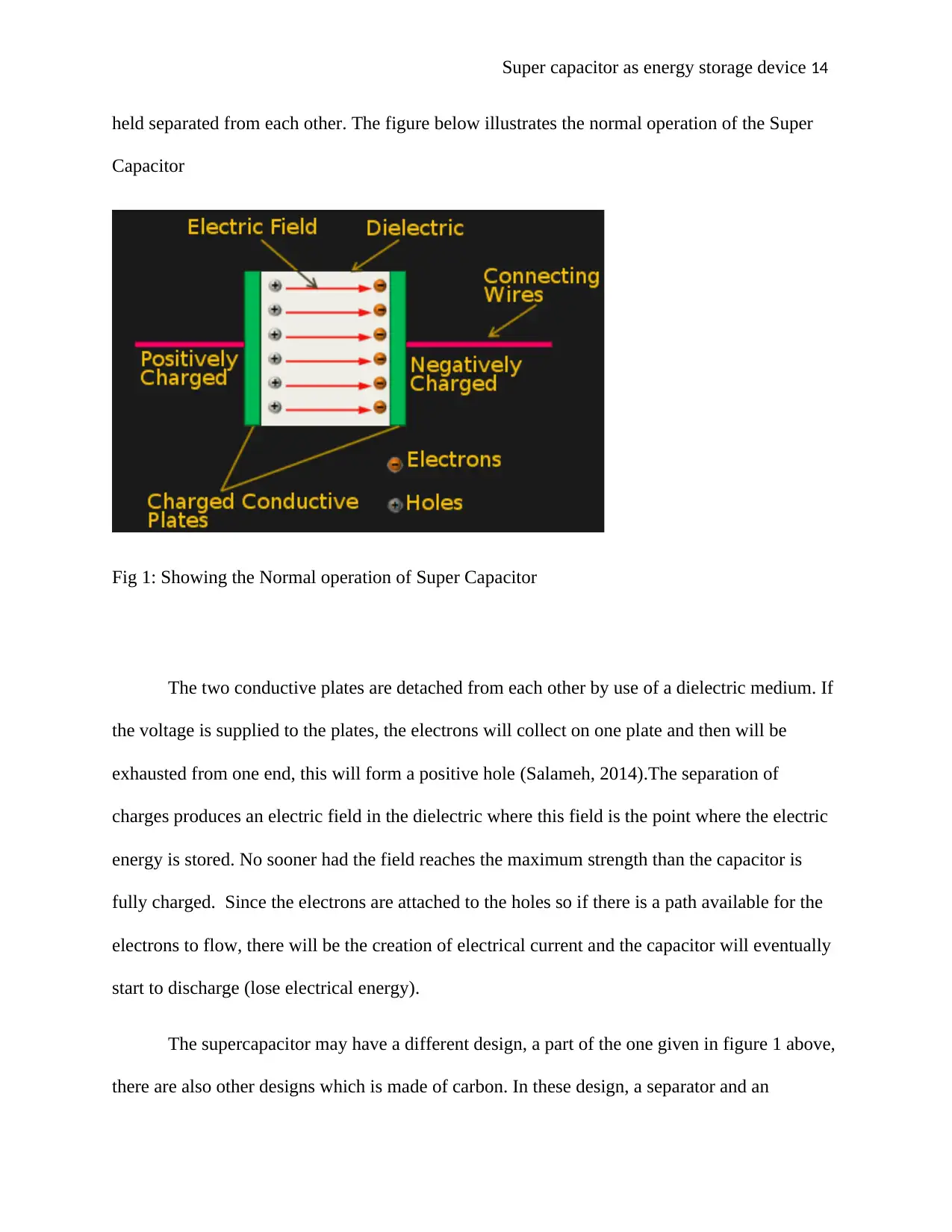
held separated from each other. The figure below illustrates the normal operation of the Super
Capacitor
Fig 1: Showing the Normal operation of Super Capacitor
The two conductive plates are detached from each other by use of a dielectric medium. If
the voltage is supplied to the plates, the electrons will collect on one plate and then will be
exhausted from one end, this will form a positive hole (Salameh, 2014).The separation of
charges produces an electric field in the dielectric where this field is the point where the electric
energy is stored. No sooner had the field reaches the maximum strength than the capacitor is
fully charged. Since the electrons are attached to the holes so if there is a path available for the
electrons to flow, there will be the creation of electrical current and the capacitor will eventually
start to discharge (lose electrical energy).
The supercapacitor may have a different design, a part of the one given in figure 1 above,
there are also other designs which is made of carbon. In these design, a separator and an
electrolyte which allows the movement of ions in this electrolyte (Patrick, 2013). When the
voltage is supplied to the electrode the negative ions will move to the positive electrode while the
positive ions will move to the negative electrode. Electric charges will thus accumulate at the
surface of both the electrodes of the positive and negative electrodes. This will thus form a
double layer (giving it the name electric double layer capacitor) every double layer of the
electrode operates as the simple capacitor. Hence the supercapacitor is an effective two capacitor
put in a series design (Kolhe, 2014).
The capacitance in the supercapacitor is relatively large as compared to the normal
capacitor due to the fact that capacitance that is directly proportional to the electrical energy
which the supercapacitor can store (Madali, 2013). The capacitance is also directly proportional
to the cross-sectional area of the plates and is inversely proportional to the distance of separation
of the plates. For the normal capacitors, the plate separation is simply the thickness of the
dielectric (this thickness is in the order of tens of microns).But for the supercapacitors, that
thickness distance is in the order of nanometers. The carbon technology employed in the
supercapacitor electrode permits for much surface area. This thickness separation is spongy in
nature and makes the operational surface area of about 100 000 times the greater than the square
area of the electrode.
These supercapacitors have both positive and negative electrode always made up of
activated carbon material. Charges here are stored in an electric double layer. There will be a
separator between the electrodes. This electrolyte separator is always a liquid in state and it is
also conductive (Jing, 2010).
⊘ This is a preview!⊘
Do you want full access?
Subscribe today to unlock all pages.

Trusted by 1+ million students worldwide
Charging the Super Capacitor storage device
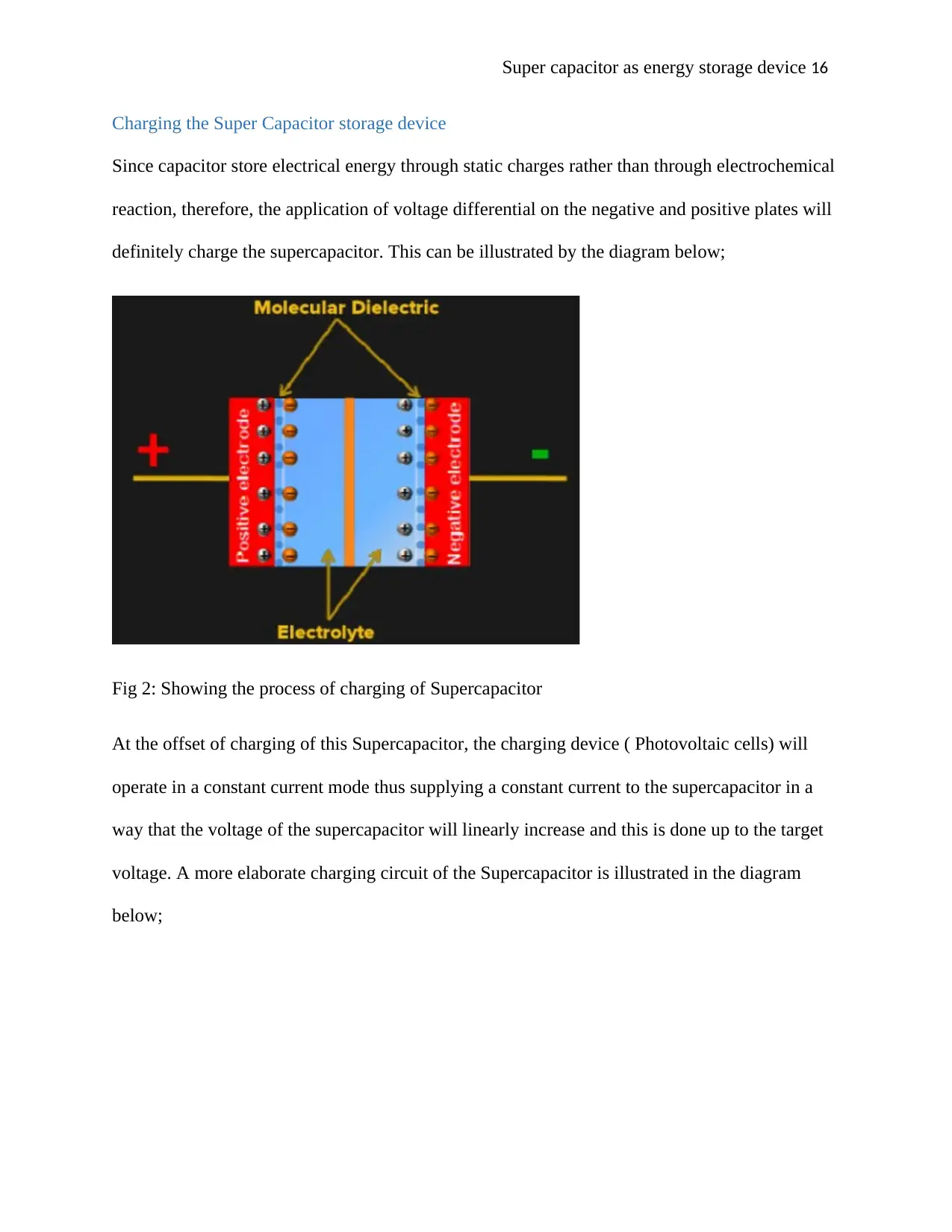
Since capacitor store electrical energy through static charges rather than through electrochemical
reaction, therefore, the application of voltage differential on the negative and positive plates will
definitely charge the supercapacitor. This can be illustrated by the diagram below;
Fig 2: Showing the process of charging of Supercapacitor
At the offset of charging of this Supercapacitor, the charging device ( Photovoltaic cells) will
operate in a constant current mode thus supplying a constant current to the supercapacitor in a
way that the voltage of the supercapacitor will linearly increase and this is done up to the target
voltage. A more elaborate charging circuit of the Supercapacitor is illustrated in the diagram
below;
Paraphrase This Document
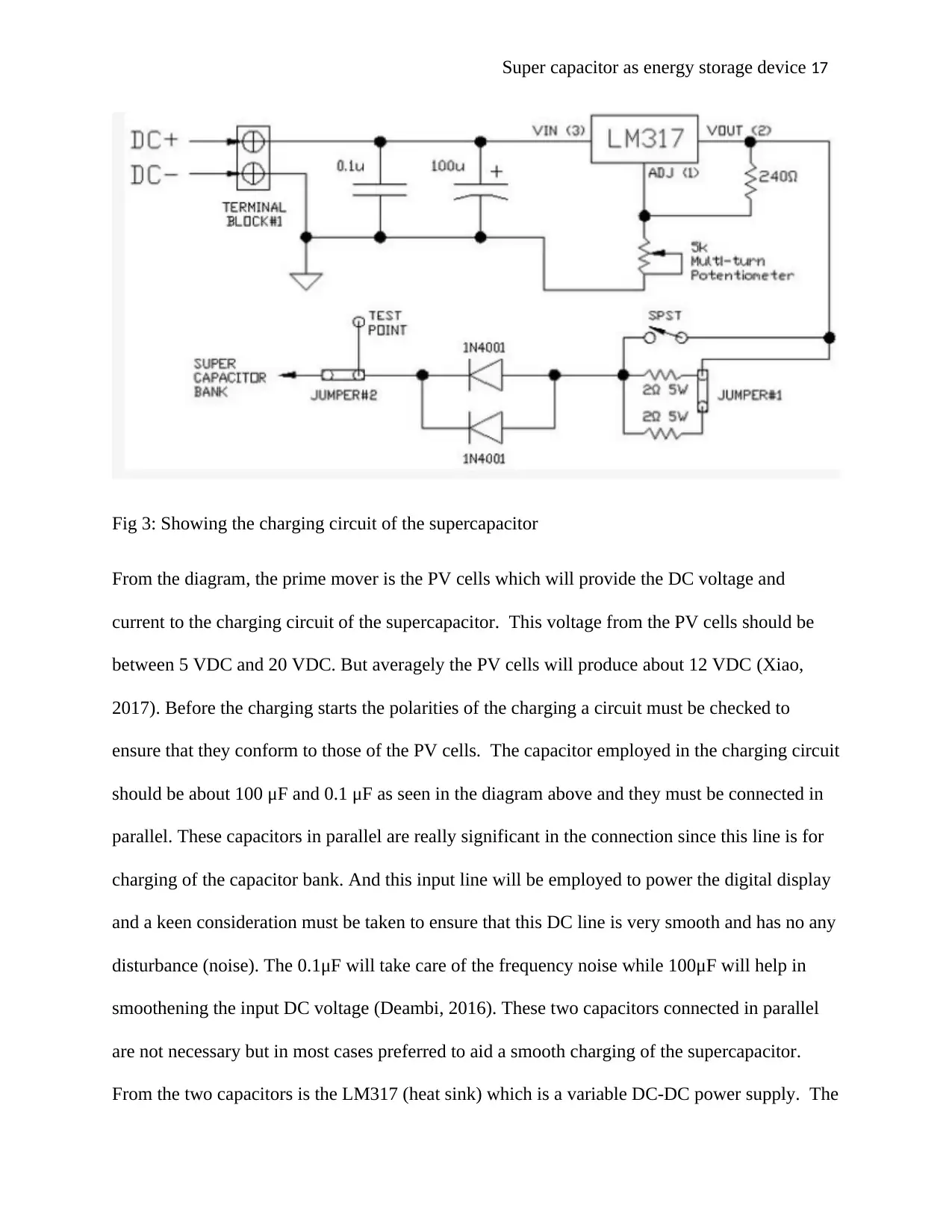
Fig 3: Showing the charging circuit of the supercapacitor
From the diagram, the prime mover is the PV cells which will provide the DC voltage and
current to the charging circuit of the supercapacitor. This voltage from the PV cells should be
between 5 VDC and 20 VDC. But averagely the PV cells will produce about 12 VDC (Xiao,
2017). Before the charging starts the polarities of the charging a circuit must be checked to
ensure that they conform to those of the PV cells. The capacitor employed in the charging circuit
should be about 100 μF and 0.1 μF as seen in the diagram above and they must be connected in
parallel. These capacitors in parallel are really significant in the connection since this line is for
charging of the capacitor bank. And this input line will be employed to power the digital display
and a keen consideration must be taken to ensure that this DC line is very smooth and has no any
disturbance (noise). The 0.1μF will take care of the frequency noise while 100μF will help in
smoothening the input DC voltage (Deambi, 2016). These two capacitors connected in parallel
are not necessary but in most cases preferred to aid a smooth charging of the supercapacitor.
From the two capacitors is the LM317 (heat sink) which is a variable DC-DC power supply. The
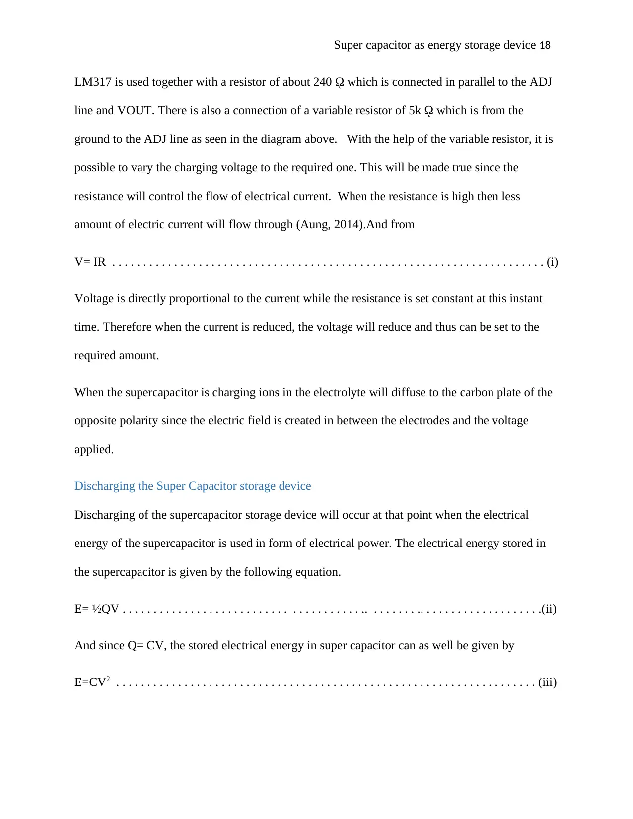
LM317 is used together with a resistor of about 240 ῼ which is connected in parallel to the ADJ
line and VOUT. There is also a connection of a variable resistor of 5k ῼ which is from the
ground to the ADJ line as seen in the diagram above. With the help of the variable resistor, it is
possible to vary the charging voltage to the required one. This will be made true since the
resistance will control the flow of electrical current. When the resistance is high then less
amount of electric current will flow through (Aung, 2014).And from
V= IR . . . . . . . . . . . . . . . . . . . . . . . . . . . . . . . . . . . . . . . . . . . . . . . . . . . . . . . . . . . . . . . . . . . . . . (i)
Voltage is directly proportional to the current while the resistance is set constant at this instant
time. Therefore when the current is reduced, the voltage will reduce and thus can be set to the
required amount.
When the supercapacitor is charging ions in the electrolyte will diffuse to the carbon plate of the
opposite polarity since the electric field is created in between the electrodes and the voltage
applied.
Discharging the Super Capacitor storage device
Discharging of the supercapacitor storage device will occur at that point when the electrical
energy of the supercapacitor is used in form of electrical power. The electrical energy stored in
the supercapacitor is given by the following equation.
E= ½QV . . . . . . . . . . . . . . . . . . . . . . . . . . . . . . . . . . . . . . .. . . . . . . . .. . . . . . . . . . . . . . . . . . . .(ii)
And since Q= CV, the stored electrical energy in super capacitor can as well be given by
E=CV2 . . . . . . . . . . . . . . . . . . . . . . . . . . . . . . . . . . . . . . . . . . . . . . . . . . . . . . . . . . . . . . . . . . . . (iii)
⊘ This is a preview!⊘
Do you want full access?
Subscribe today to unlock all pages.

Trusted by 1+ million students worldwide
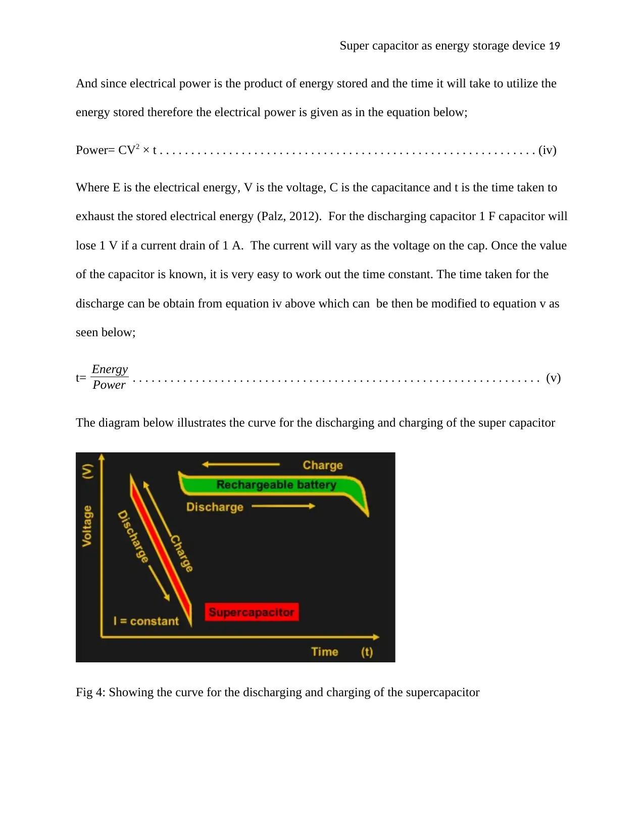
And since electrical power is the product of energy stored and the time it will take to utilize the
energy stored therefore the electrical power is given as in the equation below;
Power= CV2 × t . . . . . . . . . . . . . . . . . . . . . . . . . . . . . . . . . . . . . . . . . . . . . . . . . . . . . . . . . . . . (iv)
Where E is the electrical energy, V is the voltage, C is the capacitance and t is the time taken to
exhaust the stored electrical energy (Palz, 2012). For the discharging capacitor 1 F capacitor will
lose 1 V if a current drain of 1 A. The current will vary as the voltage on the cap. Once the value
of the capacitor is known, it is very easy to work out the time constant. The time taken for the
discharge can be obtain from equation iv above which can be then be modified to equation v as
seen below;
t= Energy
Power . . . . . . . . . . . . . . . . . . . . . . . . . . . . . . . . . . . . . . . . . . . . . . . . . . . . . . . . . . . . . . . . . (v)
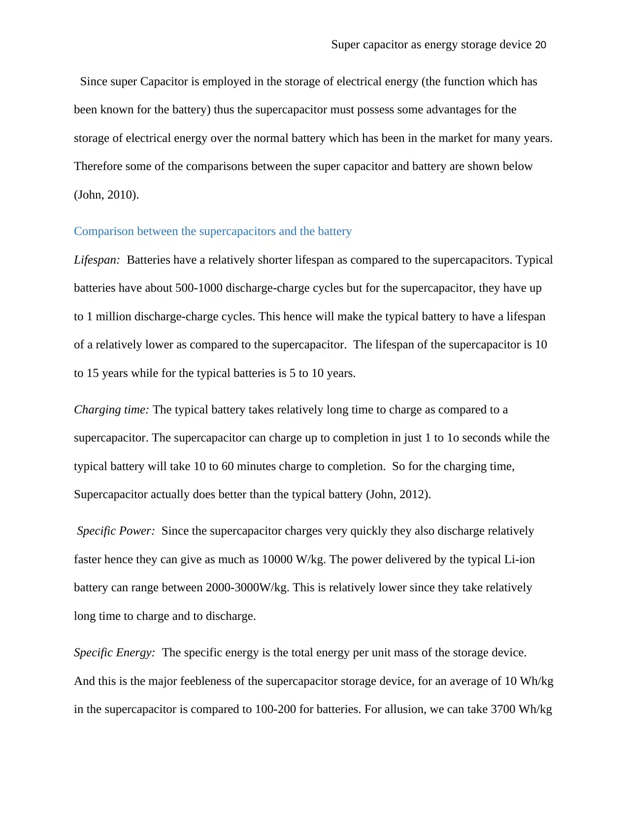
The diagram below illustrates the curve for the discharging and charging of the super capacitor
Fig 4: Showing the curve for the discharging and charging of the supercapacitor
Paraphrase This Document
Since super Capacitor is employed in the storage of electrical energy (the function which has
been known for the battery) thus the supercapacitor must possess some advantages for the
storage of electrical energy over the normal battery which has been in the market for many years.
Therefore some of the comparisons between the super capacitor and battery are shown below
(John, 2010).
Comparison between the supercapacitors and the battery
Lifespan: Batteries have a relatively shorter lifespan as compared to the supercapacitors. Typical
batteries have about 500-1000 discharge-charge cycles but for the supercapacitor, they have up
to 1 million discharge-charge cycles. This hence will make the typical battery to have a lifespan
of a relatively lower as compared to the supercapacitor. The lifespan of the supercapacitor is 10
to 15 years while for the typical batteries is 5 to 10 years.
Charging time: The typical battery takes relatively long time to charge as compared to a
supercapacitor. The supercapacitor can charge up to completion in just 1 to 1o seconds while the
typical battery will take 10 to 60 minutes charge to completion. So for the charging time,
Supercapacitor actually does better than the typical battery (John, 2012).
Specific Power: Since the supercapacitor charges very quickly they also discharge relatively
faster hence they can give as much as 10000 W/kg. The power delivered by the typical Li-ion
battery can range between 2000-3000W/kg. This is relatively lower since they take relatively
long time to charge and to discharge.
Specific Energy: The specific energy is the total energy per unit mass of the storage device.
And this is the major feebleness of the supercapacitor storage device, for an average of 10 Wh/kg
in the supercapacitor is compared to 100-200 for batteries. For allusion, we can take 3700 Wh/kg
of petrol fuel. Vis-à-vis energy per given volume supercapacitors are as well far behind at 15
Wh/L, and 1200 Wh/L for batteries.
Cost: Since the Super capacitor is a relatively new technology, they are still relatively expensive
as compared to the typical battery, with a cost of around $20 per watt, while batteries are much
cheaper in the range $0.5-$1 per watt. But there are expectations of the prices of the
supercapacitor to reduce as low as the price of the typical batteries (Zhuk, 2010).
Albeit supercapacitor have the several benefits over the typical batteries but still, they
have some drawbacks as compared to batteries: the super capacitor's voltage reduces roughly
linearly with stored electrical charge (Makahya, 2013). But with typical batteries, they keep an
approximately constant voltage until they are nearly exhausted. That implies that extra circuitry
is required to uphold voltage at an operational level when employing the supercapacitors, and
using some energy in the process. The average voltage of supercapacitors ranges between 2.5V
to 2.7V and, as with batteries one may connect them in series for higher voltage yield.
Nevertheless, there are small discrepancies in capacitance and equivalent series resistance among
specific supercapacitors, this may cause irregular voltage distribution.
Overvolting a supercapacitor rapidly results in a letdown, thus harmonizing circuits are
required to guarantee voltage on each supercapacitor is almost the same. This supercapacitor
will hence be employed for the on-grid PV electrical generation (Paul, 2013). This storage device
will hence be employed to enable the generators of the electrical energy to supply a continuous
electrical energy even if there is no sunlight (cloudy days or at night). This will also help to
avoid the notion of used as generated. There are sometimes when no one will be in need of the
electrical energy and a lot of energy is generated ( supply is surplus without any demand).
⊘ This is a preview!⊘
Do you want full access?
Subscribe today to unlock all pages.

Trusted by 1+ million students worldwide
During these times electrical energy generated will be stored in the Supercapacitor and
then the electrical energy will be retrieved when the generation is low but the demand is high.
And since this is for the on-grid there is a need of a continuous supply of electrical power
regardless of the time of the day, nature of the weather and the demand of electrical energy
(Xhing, 2012).And for that matter, Supercapacitors will be employed to ensure that electrical
energy is supplied to the demanded area through the grid. Therefore supercapacitor will as well
ensure there is feedback to grid in time for the generation of electrical energy which ensures a
continuous generation and distribution of electrical energy (Mchappah, 2013).
With the supercapacitor storage device, individuals can start the business of renewable
power generation. This will be highly encouraged into the society since the energy is very clean,
free from the sound pollution and very green as it helps environment conservation. This is true
due to the sufficient amount of energy which can be stored in the supercapacitor and the power it
is able to supply to the grid (Jachumbi, 2010). The individual with this kind of plant can use it as
domestic power supply where the surplus is connected to the grid (this help in eliminating the
wastage of electric energy).
So during the day banks of supercapacitors are connected to the PV power supply be
charged and during the night or the cloudy days when there is no sunlight the stored electrical
energy is retrieved and supplied to the demanded areas (Kitweck, 2010). With the use of the
supercapacitor as the energy storage device, it is possible to use PV cell in the generation
commercial electrical power. Several PV cells are connected either in parallel or in series and
then these are connected to the bank Super capacitor storage device (Santos, 2011).When these
capacitors are charged (during the day ) some energy is employed in charging the supercapacitor
to be used at a later time while others are directly connected to the grid.
Paraphrase This Document
The amount of energy needed to charge the supercapacitor may be determined by using a
PIC module. This is obtained in percentage form, the PIC module will as well help to maintain
the amount of electrical energy that goes to the Supercapacitor and the portion which goes to the
grid to be used somewhere where it is demanded (Freundlich, 2017). The bank of
supercapacitors can supply a lot of electrical energy after they are completely charged from the
PV cells. This is realized when the supercapacitor is connected in series in their bank.
Supercapacitor will also help in feedback to the grid in time when the stability of electrical
power generation is needed. Therefore when this new technology is fully put into practice it will
definitely make it easy for individuals get access to electrical energy as there will be a very
stable supply of electrical energy from renewable PV cell supply (Rodriguez, 2011).
The government and other organizations (environmental) will highly promote the
adoption and implementation of this type of energy generation because of the health and
environmental conservation importance it has. In the generation plant in some cases, there may
be a buck-boost converter employed to aid in the energy conversion. This is not a must but
preferred. Where the buck-boost is not is not used an ordinary inverter is employed in the energy
conversion. The buck-boost converter is employed for the DC-DC converter and this is only
employed when a DC output is required at the output. The DC-DC buck-boost converter can be
employed instead of a transformer (Foster, 2010). When the AC power is needed then there is no
need for the buck-boost converter instead we will use the inverter to first convert the DC
generated to AC power. For the on-grid power generation, the AC power is very important since
it can be stepped up before being transmitted. Stepping up the voltage will help reduce the
voltage loss during the transmission. This is true since when the voltage is stepped up the current
will be stepped down as in the below equation and power is taken to be constant.
P=VI . . . . . . . . . . . . . . . . . . . . . . . . . . . . . . . . . . . . . . . . . . . . . . . . . . . . . . . . . . . . . . . . . . . . (vii)
And from the equation of power loss seen below, if the current is reduced and then squared it
will be reduced further
P=I2R . . . . . . . . . . . . . . . . . . . . . . . . . . . . . . . . . . . . . . . . . . . . . . . . . . . . . . . . . . . . . . . . . . . . (vii)
The amount of the voltage at the secondary coil will hence depend on the turn ratio of the
transformer. The PV cell and the Super capacity storage device are both set at the primary part
of the transformer and they must be before the inverter. The whole system will be synchronized
such that when the Supercapacitor is fully charged then the power generated from the PV cell
moves fully to the grid through the inverter and the transformer (Stoller, 2008). And during the
night when there is no sunlight the bank of the super capacitor will then be connected to the
system to provide power to the grid. During the day there is no electrical power from the bank
which will flow through the system (unless it is a fully cloudy day). This connection and
disconnection are realized through the use of the light dependent resistor (LDR).
Advantages of supercapacitors
High energy storage capability. Supercapacitors pose high capability of storing large
amounts of energy when compared to the technologies of conventional capacitors. This is
enabled through the use of porous activated electrodes of carbon with an aim of achieving
an increased storage surface area.
Reduced equivalent series resistance when compared to other energy storage technologies
such as batteries. In addition, EDLCs poses low internal resistance thus enhancing the
high capability of power density.
⊘ This is a preview!⊘
Do you want full access?
Subscribe today to unlock all pages.

Trusted by 1+ million students worldwide
Ability to perform at low temperature. Supercapacitors are capable of delivering energy
up to a down limit of -40degrees Celsius with almost a zero effect on efficiency.
Quick charge and discharge. High current charging or discharging is easily achieved by
the supercapacitors due to charging and discharging achievement by the EDLCs via the
ions absorption and releasement in presence to its low ESR (Arico, 2010).
Limitations and challenges of using supercapacitors
Despite supercapacitors having numerous sensitive advantages over other energy storage
technologies, it also poses challenges which are experienced through its use in the solar energy
generation. This includes the following:
Presence of low voltage per cell. Cells of EDLC poses a low voltage capability of 2.7V
and from the fact that most energy applications demand more energy, this problem has
been always considered to be solved through series connection of the cells
Demands limited use of AC and circuits of high frequency as a result of its time constant
making EDLCs less preferred for an AC and high-frequency use.
Regardless of the advantages and limitations experienced from the application of
supercapacitors, the exact specification of these ultra-capacitors highly relies on the
manufacturers and the desired expectation needed from a capacitor. A slight difference in
materials used in its development might also too differ in relation to requirements application
(Simon, 2008).
RELATIVE DATA AND STATISTICS
The supercapacitor is a new technology which has not been fully implemented and
adopted into practice in the storage of electrical energy. This is because of its cost is relatively
Paraphrase This Document
higher than that for the typical battery (James, 2012). For that matter, the number of the
supercapacitor is relatively low in the market as well as in practice. In countries like for example
Indian in the year 2013, supercapacitor application in term of percentage is shown below;
No Application Usage percentage
1 Mobile phone 51
2 LED display 23
3 Memory backups for video and audio experiment 13
4 Wind turbine controllers 7.2
5 Others 5.4
And for the renewable energy generated through PV cells which are stored in the supercapacitor
and connected to the grid, China as a country which has highly invested in the PV cell electricity
generation expects to adopt this new technology of energy storage where the generation of
electricity is expected to be as follows;
No Power Plant Relative percentage
1 Hydropower 41%
2 Thermal power 29%
3 Windmill power 22%
4 Solar power 08%
But if the adoption and implementation of the supercapacitor are fully done in China then there
will be more percentage of electrical energy generated through the PV cells as now there is a lot
of power which are lost due to inappropriate storage of electrical energy (Abbey, 2013).This is
because the battery has never been a perfect storage as compared to the supper capacitor storage
device. The number of percentage of electricity generated from the solar plant worldwide still
appear very small almost negligible due to the power wastage which is witnessed in the battery
storage device (Karumba, 2012). The number is expected to rise to about 20% with the full
implementation of the supercapacitor storage device.
FUTURE ASPECTS OF SUPER CAPACITOR
The supercapacitor is expected to be improved further to make it more efficient than the
present one. There is an expectation of developing a micro supercapacitor. This type of
supercapacitor is able to store more energy at about six times that stored by normal and present
supercapacitor. The micro supercapacitor is a very thin supercapacitor which is able to charge
within a very short time and stores a lot of energy which will hence be used for a long time
making its discharge time to be relatively longer. Researchers have it that with the micro-
supercapacitor, it will be used as a handheld the electronic battery.
Since the micro-supercapacitor is able to charge within a very short time it can hence be
charged through solar cells during the day when there is sunlight and then the stored energy is
then used during the night when there is no sunlight. The dramatic increase in tablet, smartphone
and laptops have brought the battery to frontline for the storage. Therefore, this has made several
⊘ This is a preview!⊘
Do you want full access?
Subscribe today to unlock all pages.

Trusted by 1+ million students worldwide
researchers to look for a storage device which can store more power and charge within a very
short time like that for the micro-supercapacitor (Jacob, 2012). These micro-supercapacitors
have charging cycles of 10000. Hence in near future when this micro supercapacitor is employed
in the storage it will highly help in the supply and generation of electricity through PV cell.
These micro super capacitor being small will definitely be employed in the electronic
components since they are very small (not bulky) and very powerful. These micro-
supercapacitors are expected to be employed in the energy generation using the PV cell where
they will be put in a bank. And being that they are very small, more of them can be packed
together hence a lot of energy can be stored to be employed during the night or when there is less
or no sunlight. There is an expectation of an increase in the power supply from the solar
generation plant with the invention of these micro-supercapacitors storage devices. This
invention will probably make most individuals to prefer the solar energy since it is very clean
and it is renewable hence relatively cheap as compared to other forms like the coal and nuclear
generation plants.
CONCLUSION
To help solve the bottleneck of the battery as a technology for electrical energy storage, a
supercapacitor in this paper basically discusses the criteria on how a supercapacitor is employed
in the storage of electrical energy as well as why it is employed and not the battery.
Energy storage system is required to help in the continuous supply of electrical energy
after generation. And since the solar photovoltaic cells produce relatively less electrical energy,
the storage is required to help reduce the power loss which might be realized in the generation
when the electrical energy is not in use. This is because the electrical power demand always
Paraphrase This Document
fluctuates highly and consequently power stations should be overdesigned which illustrates
expensive and inefficient electrical system. Therefore with the invention of the supercapacitor
(micro supercapacitor and supercapacitor), there will be a serious increase in the adoption of
usage of solar in electricity generation.This is true since this supercapacitor will be charged to
the full capacity with a very short time and then take a relatively long time to discharge (used).
The increase in the usage of the supercapacitor will in turn result to increase usage of solar in the
generation of electricity. This makes the world to move to a pollution-free generation of
electricity.
REFERENCES
Abbey, J., 2013. Will Super capacitor completely outdo battery is energy storage ?. 2nd ed. Hull:
Adventure.
Ali, S., 2011. Smart Grids: Opportunities, Developments, and Trends. 2nd ed. Hull: Springer Science &
Business Media.
Aung, Z., 2014. Data Analytics for Renewable Energy Integration: Second ECML PKDD Workshop. 1st ed.
Ottawa: Springer.
Boxwell, M., 2011. Solar electricity handbook. 2nd ed. London: Springer.
Charles, 2012. Application of supercapacitor. 2nd ed. Hull: CRC.
Conway, E., 2013. Electrochemical Supercapacitors: Scientific Fundamentals and Technological
Applications. 3rd ed. Florida : Springer Science & Business Media.
David, S., 2011. operation of a supercapacitor. 2nd ed. Stoke: Springer.
Deambi, S., 2016. Photovoltaic System Design: Procedures, Tools and Applications. 2nd ed. London: CRC
Press.
Delnick, M., 2011. Proceedings of the Symposium on Electrochemical Capacitors II. 2nd ed. Ottawa: The
Electrochemical Society.
Engineers, S. o. A., 2011. Hybrid Vehicle and Energy Storage Technologies. 1st ed. Hull: CRC.
Fardoun, A. A., 2017. ICREGA’14 - Renewable Energy: Generation and Applications. 3rd ed. Birmingham:
Springer.
Feaver, A., 2010. Carbon Cryogel Based Nanomaterials for Efficient Energy Storage. 1st ed. Florida:
University of Washington.
Foster, R., 2010. Solar Energy: Renewable Energy and the Environment. 2nd ed. London: CRC Press.
Frackowiak, E., 2013. Supercapacitors: Materials, Systems, and Applications. 3rd ed. London: John Wiley
& Sons.
Freundlich, A., 2017. Photovoltaic Solar Energy: From Fundamentals to Applications. 2nd ed.
Amsterdam: John Wiley & Sons.
Gevorkian, P., 2012. On-grid power of Pv. 3rd ed. Chicago: CRC.
Hoffmann, V. U., 2015. Photovoltaic Solar Energy Generation. 2nd ed. Berlin: Springer Science & Business
Media.
Jachumbi, B., 2010. Energy storage using Supercapacitor. 2nd ed. Florida: Springer.
Jack, H., 2014. Energy devices: Use of Capacitor in energy storage. 2nd ed. Stoke: Adventure press.
⊘ This is a preview!⊘
Do you want full access?
Subscribe today to unlock all pages.

Trusted by 1+ million students worldwide
Jacob, K., 2012. Lead Markets for Environmental Innovations for a supercapacitor. 2nd ed. Stoke:
Springer Science & Business Media.
James, K., 2012. PV electricity generation. 2nd ed. Stoke: Springer.
James, N., 2010. Application of supercapacitor in energy generation. 2nd ed. Ottawa: Springer.
Jelley, A., 2013. Energy Science: Principles, Technologies, and Impacts. 2nd ed. Chicago: OUP Oxford.
Jing, Z., 2010. Supercapacitor present and future: Developing micro supercapacitor. Hawaii: CRC2nd.
John, D., 2012. Solar PV Power: a global perspective. 2nd ed. Amsterdam: CRC.
John, R., 2010. Application of supercapacitor in the generation of electricity. 2nd ed. Manchester:
Springer.
jose, K., 2012. Supercapacitor for energy storage. 1st ed. Madrid: CRC.
Kumba, R., 2012. Electricity generation through PV. 1st ed. Chicago: CRC.
Kitweck, A., 2010. Electrical energy generation through renewable sources of energy. 1st ed. Hull:
Springer.
Kolhe, M., 2014. Solar Photovoltaic System Applications: A Guidebook for Off-Grid Electrification. 2nd ed.
Manchester: Springer.
Komoto, K., 2013. Energy from the Desert: Very large scale photovoltaic power--state of the art and into
the future. 2nd ed. Madrid: Routledge.
Krauter, S., 2012. Solar Electric Power Generation - Photovoltaic Energy Systems: Modeling of Optical
and Thermal Performance, Electrical Yield, Energy Balance, Effect on Reduction of Greenhouse Gas
Emissions. 1st ed. Leicester: Springer Science & Business Media.
Kularatna, N., 2014. Energy Storage Devices for Electronic Systems: Rechargeable Batteries and
Supercapacitors. 2nd ed. Hull: Academic Press.
Madali, I., 2013. How Supercapacitor is used in power storage. 2nd ed. Stoke: CRC.
Makahya, L., 2013. Supercapacitor usage in the storage of electrical energy. 2nd ed. Hull: Adventure.
Ma, M., 2011. Communication Systems and Information Technology:. 1st ed. Chicago: Springer Science &
Business Media.
Mchappah, L., 2013. PV cells in the on-grid energy generation. 1st ed. Stoke: CRC.
Miller, J., 2011. Ultracapacitor Applications. 3rd ed. Chicago: Institution of Engineering and Technology.
Montana, S., 2012. Supercapacitors in energy generation. 2nd ed. Stoke: Springer.
Nkuka, J., 2010. Electrical power converters: DC buck-boost converters. 1st ed. Paris: Springer.
Onkari, D., 2010. PV power generation of on-grid. 4th ed. Hull: Springer.
Palz, W., 2012. Photovoltaic Power Generation. 2nd ed. Colorado: Taylor & Francis.
Paraphrase This Document
Partain, L., 2010. Solar Cells and their Applications. 2nd ed. Washington DC: CRC.
Patrick, E., 2013. Generation of renewable. 2nd ed. Hull: CRC.
Paul, B., 2013. Supercapacitor application in power storage. 2nd ed. Hawaii: Springer.
Peng, H., 2015. Fiber-Shaped Energy Harvesting and Storage Devices. 1st ed. Hull: Springer.
Peng, H., 2015. Fiber-Shaped Energy Harvesting and Storage Devices. 4th ed. Florida: Springer.
Rodriguez, P., 2011. Grid Converters for Photovoltaic and Wind Power Systems. 2nd ed. Hawaii: John
Wiley & Sons.
Salameh, Z., 2014. Renewable Energy System Design. 2nd ed. Stoke: Academic Press.
santos, J. D., 2011. On-grid electricity generation using the PV. 1st ed. Hull: Adventure works.
Sanz-Bobi, 2014. Use, Operation and Maintenance of Renewable Energy Systems: Experiences and
Future Approaches. 1st ed. Manchester: Springer.
Srinivasan, S., 2010. proceedings of the Symposium on Electrode Materials and Processes for Energy
Conversion and Storage. 2nd ed. Ottawa: The Electrochemical Society.
Tagare, D., 2011. Electricity Power Generation: The Changing Dimensions. 2nd ed. Hull: John Wiley &
Sons.
Turpin, C., 2012. Electrochemical Components. 1st ed. Toronto: John Wiley & Sons.
Wang, W., 2013. Mechatronics and Automatic Control Systems: Proceedings of the 2013 International
Conference on Mechatronics and Automatic Control Systems (ICMS2013). 1st ed. Colorado: Springer
Science & Business Media.
Xhing, P., 2012. Super capacitor replacing batteries in energy storage. 3rd ed. Florida: CRC.
Xiao, W., 2017. Photovoltaic Power System: Modeling, Design, and Control. 3rd ed. Chicago: John Wiley
& Sons.
Zhang, J., 2012. Electrochemical Supercapacitors for Energy Storage and Delivery: Fundamentals and
Applications. 1st ed. Hull: CRC Press.
Zheng, H., 2012. Solar Photovoltaic Energy Generation and Conversion --from Devices to Grid
Integration. 2nd ed. Beijing: CRC.
Zhou, S., 2013. Advances in Battery Manufacturing, Service, and Management Systems. 3rd ed. Hull:
John Wiley & Sons.
Zhou, X., 2014. Graphene: Energy Storage and Conversion Applications. 5th ed. Amsterdam: CRC Press.
Zhuk, R., 2010. Generation of renewable energy: Using PV cells in the generation of electrical energy. 2nd
ed. Hull: Springer.
Simon, P., 2008. Materials for electrochemical capacitors. Nature materials,
Aricò, W., 2010. Nanostructured materials for advanced energy conversion and storage devices.
Nature materials,
Stoller,.S., 2008. Graphene-based ultracapacitors. Nano letters,
Barsoukov, E., 2011. Impedance spectroscopy: theory, experiment, and applications.
Kötz, M., 2013. Principles and applications of electrochemical capacitors.
Wang, J., 2012. A review of electrode materials for electrochemical supercapacitors. Chemical
Society Reviews,
⊘ This is a preview!⊘
Do you want full access?
Subscribe today to unlock all pages.

Trusted by 1+ million students worldwide
Related Documents
Your All-in-One AI-Powered Toolkit for Academic Success.
+13062052269
info@desklib.com
Available 24*7 on WhatsApp / Email
![[object Object]](/_next/static/media/star-bottom.7253800d.svg)
© 2024 | Zucol Services PVT LTD | All rights reserved.


