Switched Reluctance Motor Controller Design and Implementation
VerifiedAdded on 2023/06/14
|70
|12911
|368
Report
AI Summary
This report provides a comprehensive overview of switched reluctance motor (SRM) controller design. It begins with an introduction to SR motors, highlighting their construction and advantages. The report then delves into the controller design, discussing various control strategies such as voltage PWM and angular position control. It also covers the hardware design, focusing on the power converter, rotor position detection using photoelectric sensors, and phase current detection. The software design section explains the use of DSP C language and modular programming. The document emphasizes the importance of addressing nonlinear properties and challenges in SRM control, aiming to provide a reliable and efficient motor drive system. The report concludes by referencing key components like the TMS320F2812 DSP chip and IGBT modules, offering a detailed insight into the practical implementation of an SRM controller.

Electrical Engineering 1
ELECTRICAL ENGINEERING
By Name
Course
Instructor
Institution
Location
Date
ELECTRICAL ENGINEERING
By Name
Course
Instructor
Institution
Location
Date
Paraphrase This Document
Need a fresh take? Get an instant paraphrase of this document with our AI Paraphraser

Electrical Engineering 2
Introduction;
Switched reluctance motor is a brushless AC motor, it is always referred to as SR. This
motor has a very easy mechanical construction and it doesn't need a permanent magnet for it to
work perfectly. It rotor and starter always have main poles. There is no exact number of the
poles on the starter since this will always depend on the number of phases the motor is made to
work on. Usually, one phase of this motor is realized through having two stator poles at opposite
ends. And in this arrangement, a three-phase can be realized by having 6 starter poles. The
number of poles of the rotor is selected not to be the same to the number of poles of the stator
(Gieras, 2014).
SR motor will contain the phase winding only on its stator. Intense windings are always
employed for such motor (Miller, 2014). The windings are put onto the poles of the stator and
then connected in series in order to make one phase of the motor. For a three Phase motor, there
must be 3 pairs of intense windings where each pair of the winding should be connected in series
to make each phase respectively. The mechanical assembly of a 6/4 3-Phase motor is illustrated
in Figure 1 (Hughes, 2011). Other arrangements of such motor are like 4/2 2-Phase SR motor
(having uneven rotor) and 8/6 4-Phase motor is illustrated in Figure 2 and Figure 3 as shown
below.

Electrical Engineering 3
Fig 1. Fig 2 Fig 3
Fig 1: Showing the arrangements of 4/2 2-Phase SR motor (having uneven rotor) and 8/6 4-
Phase motor. (Hughes, 2011)
A real structure of the switched reluctance motor for a 4- phase machine having 4 rotor- poles
and 3 rotor pair is shown in the diagram below;
Fig 2: Showing a real structure of the switched reluctance motor for a 4- phase machine having 4
rotor- poles and 3 rotor pair. (Janardnan, 2014)
⊘ This is a preview!⊘
Do you want full access?
Subscribe today to unlock all pages.
Trusted by 1+ million students worldwide
Electrical Engineering 4
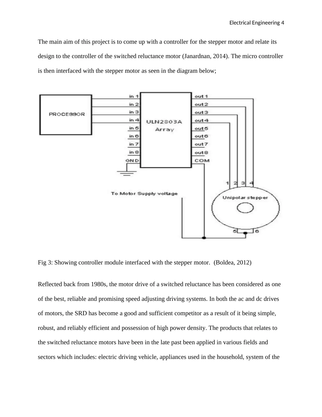
The main aim of this project is to come up with a controller for the stepper motor and relate its
design to the controller of the switched reluctance motor (Janardnan, 2014). The micro controller
is then interfaced with the stepper motor as seen in the diagram below;
Fig 3: Showing controller module interfaced with the stepper motor. (Boldea, 2012)
Reflected back from 1980s, the motor drive of a switched reluctance has been considered as one
of the best, reliable and promising speed adjusting driving systems. In both the ac and dc drives
of motors, the SRD has become a good and sufficient competitor as a result of it being simple,
robust, and reliably efficient and possession of high power density. The products that relates to
the switched reluctance motors have been in the late past been applied in various fields and
sectors which includes: electric driving vehicle, appliances used in the household, system of the
Paraphrase This Document
Need a fresh take? Get an instant paraphrase of this document with our AI Paraphraser

Electrical Engineering 5
servo, aviation industry and other many more. This has been widely achieved through the
product having much market potential.
It is however difficult creating accurate mathematical models for SRM due to the fact that
magnetic saturation causes many problems relating to nonlinear properties. In addition the SRM
mathematical model inaccuracies are also caused by the effect originating from the eddy together
with hysteresis effects. Nevertheless, the constant change in the strategy of control of the SRM
are always in consideration to the structure and parameters of the SRM thus leading to the
difficulty in achieving a reliable performance of control through the use of a pure traditional
strategy of the PID. This literature therefore discusses the fuzzy PI strategy through a
combination of PID algorithm together with fuzzy algorithm and eventually the 4 phase designs,
the 8/6 pole SRD that is basically grounded on the 32 bit digital signal processor with a general
motive of solving the previously mentioned challenges and problems. The results which are
obtained from the experiment clearly show that certain extents of the challenges and problems
originating from the effects of the nonlinear properties of the SRM can be solved by the scheme.
Strategy of control and structure of the system
The power converter, SRM, detector and the controller are usually the main or major
components of the SRD system. The SRM structure is shown in the below figure 1 of the
literature. Through the control of the motors current of winding switch, the 4-phase, SRM 8/6
pole, power converter energy is transferred. The SRD systems normally have the controller as
the core part or component which is capable of adjusting the current at the phase and the SRM
speed of motor. In addition, its properties greatly and directly have impacts on the SRD system
performance. Rotor position detection and the detection of the winding current forms the general
Electrical Engineering 6
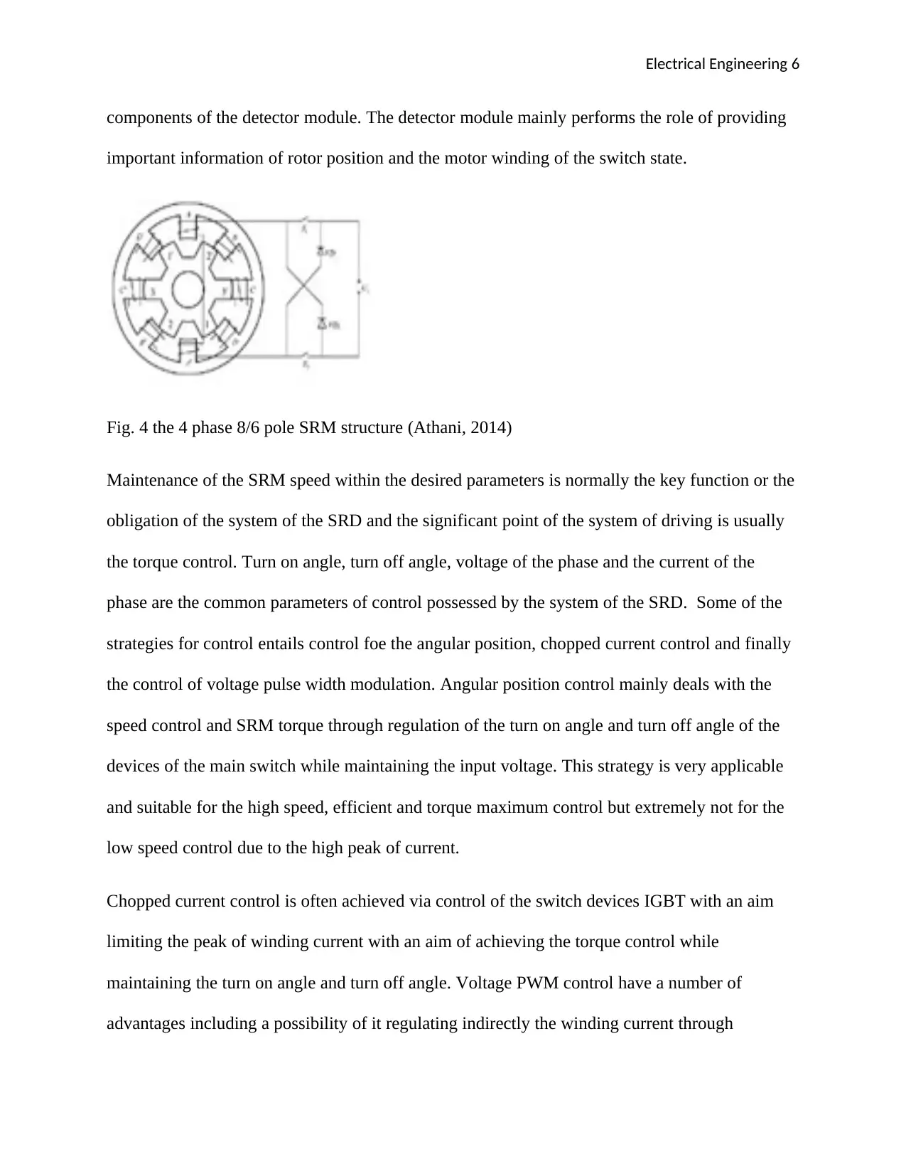
components of the detector module. The detector module mainly performs the role of providing
important information of rotor position and the motor winding of the switch state.
Fig. 4 the 4 phase 8/6 pole SRM structure (Athani, 2014)
Maintenance of the SRM speed within the desired parameters is normally the key function or the
obligation of the system of the SRD and the significant point of the system of driving is usually
the torque control. Turn on angle, turn off angle, voltage of the phase and the current of the
phase are the common parameters of control possessed by the system of the SRD. Some of the
strategies for control entails control foe the angular position, chopped current control and finally
the control of voltage pulse width modulation. Angular position control mainly deals with the
speed control and SRM torque through regulation of the turn on angle and turn off angle of the
devices of the main switch while maintaining the input voltage. This strategy is very applicable
and suitable for the high speed, efficient and torque maximum control but extremely not for the
low speed control due to the high peak of current.
Chopped current control is often achieved via control of the switch devices IGBT with an aim
limiting the peak of winding current with an aim of achieving the torque control while
maintaining the turn on angle and turn off angle. Voltage PWM control have a number of
advantages including a possibility of it regulating indirectly the winding current through
⊘ This is a preview!⊘
Do you want full access?
Subscribe today to unlock all pages.
Trusted by 1+ million students worldwide
Electrical Engineering 7
adjustments of the average value of phase windings. In addition, voltage PWM control is
propitious to both high speed and low speed drive systems. Nevertheless, it also possess a faster
dynamic response on disturbances opposing the load which is eventually significant as it aids in
achievement of an effective and reliable SRD operation performance.in consideration to all the
above characteristics or properties, this literature mainly considers voltage PWM as the key
strategy for control.
Design for the system hardware
Diagram below represents the general structure of the hardware with the control chip DSP
TMS320F2812 as a basis. In addition, figure 3 illustrate a picture of TMS320F2812 system of
PCB. TMS320F2812 as a component of the advanced 32 bit DSP chip of a fixed point, has the
capability of reaching 150MIPS as a processing speed. It too have a capability relating to signal
processing and can efficiently achieve very complicated algorithm of control.
In figure 2, the dotted line partially represents the TMS320F2812 inclusive of the all parts of
control of the system which entails the control of current, control of speed and eventually the
control for motor commutation which are fulfilled by DSP software. The power circuit is driven
by the output logic level of the PWM signal originating from the DSP hence controlling the
current and speed of the SRM. Hall current sensors detects the feedback signals which are
delivered to DSP unit of ADC with an intention of implementing the current closed loop control
as the photoelectric sensors detects the feedback signals of the rotor position and is delivered to
the DSP CAP unit with an intention of achieving the speed closed loop control. Nevertheless,
significant information relating to the speed of the motor, current of the winding phase and the
torque output are sent to the display of the LCD through the DSP interface.
Paraphrase This Document
Need a fresh take? Get an instant paraphrase of this document with our AI Paraphraser

Electrical Engineering 8
Fig 5. The switched reluctance drive system block diagram (Acarnley, 2013)
Fig 6. TMS320F2812 32 bit digital signal processor photograph (Bartelt, 2013)
The power converter design
In order to improve or enhance the operational reliability, a circuit of half bridge asymmetry is
implanted as the SRD system circuit of power. This enables each phase to be independently
controlled avoiding the phase connections and the idea of the direct connection phenomenon
existing between the arms power circuit bridge. The asymmetry half bridge possesses an
improved utilization of power in comparison to other circuits of power making it more efficient
and reliable. Figure 4 of the diagram clearly represent the asymmetry half bridge topology

Electrical Engineering 9
Fig 7. Circuit for power converter (Angila, 2014)
The power switching device 300a/1200v was chosen. It was categorically the switched device
IGBT module SKM300GB123D which is developed by the SEMIKRON Company. It contained
a number of advantages which includes a limited loss in power, an relatively higher speed of
switching and a simple circuit of driving.
The IGBT was driven by the driving module EXB841 which was developed by the FUJI
Corporation. . EXXB841 possess a separated output and input together with it being an
integrated circuit. Nevertheless, EXB841 has a capability performing the over current properties.
The EXB841 is capable of immediately disabling the trigger signals hence avoiding the IGBT
damaging in scenerios that the quantity of current limitation in the IGBT is exceeded.
Detection of the rotor position
There exist 2 rotor position signals functional aspects including:
Accurate indication of the relative position existing between the rotor and the stator.
Calculation of the SRM real time speed.
Photoelectric sensors are the position sensors adopted in this literature. Both the two sensors are
installed on the motor shell as illustrated in the figure 5 of the literature with an aim of
generating double square signals of wave possessing 15 mechanical degrees in a period of rotor
angle as the phase difference. 4 distinct positions of reference of the SRM rotor are represented
⊘ This is a preview!⊘
Do you want full access?
Subscribe today to unlock all pages.
Trusted by 1+ million students worldwide

Electrical Engineering 10
by 2 signals in four varying states. Figure 8 of the literature illustrate the position of rotor signals
obtained in the experiment. With an aim of determining the rotor position and the motor speed
after completion of the optical coupling isolation and conditioning of the signal, position signals
are delivered to DSP CAP unit.
Fig 8 : Showing position of rotor signals (Parab, 2012)
a) Stator and rotor relative position
b) Photoelectric sensors P&S relative positions
Fig 9. Detected rotor position signals by the photoelectric sensors (Krishnan, 2013)
Detection of phase current
Paraphrase This Document
Need a fresh take? Get an instant paraphrase of this document with our AI Paraphraser

Electrical Engineering 11
Within the system of SRD, phase current detection plays an essential role since it is capable of
providing the winding current information which helpful in achieving the phase current closed
loop control. The current out put sensor mode possess an improved interference resistance
capability when compared to voltage output mode sensor. This is achieved through the high
frequency power switched circuit. In relation to this literature, adoption of LT300-C current
output mode sensor is adopted with an aim of detecting the phase current. Output signals
originating from the hall current sensors are delivered to DSP ADC unit in order to obtain the
SRM value of speed immediately on completion of signal sampling and filtering processes.
Design of the system software
The DSP C language of programming is utilized together with programming method of modular
which utilized during the designing of the software. With an aim of improving the readability
and portability of the programs, subroutines are achieved through compiling of all the shared
programs together with varying functions. The components of the SRD programs of software
entails the main program, AD interrupt program, the initialization system program, the fuzzy
speed control program and the PI current control program.
Control of the motor speed
Control of the SRM speed is managed through the adoption of the fuzzy algorithm due to its
nonlinear variation of parameters suitability. Online adjustments of the PID parameters form one
of the key goals of the fuzzy controller. Analysis of the SRD system should form the basic
grounds for control strategies of the adjustments. Natural language is transformed from the input
variable by the fuzzy controller then secondly to information relating to numerical that contain a
possibility of being identified by the fuzzy controller. In order to blur the achieved results or

Electrical Engineering 12
finding, fuzzy reasoning is conducted. The below listed are the most common language
variables:
NB, NS, NM, ZE, PS, PB and lastly PB. These variables are usually selected in the fuzzy
algorithm.
The rule of control of fuzzy controller is generally derived from the operators experience and
relevant experts knowledge. The fuzzy table of control rule takes into reference the common
system features to step response and the input variables relationship. The below diagram is of
fuzzy control table
Fig 10: Showing the diagram of fuzzy control table. (Mangudi, 2013)
Phase current control
The control strategy of the PID is normally adopted in the current closed loop control. The
variables comprised in the linear proportion parameter P, combination are controlled in order to
too control the object. The integral parameter I and the differential parameter D are also
controlled. The below is a description of the discrete PID
In the closed loop control of the SRD, the differential parameter normally overreacts to the
change in the phase current resulting to the system being unstable. This forms the main reason as
to why PI algorithm has been applied in place of PID controlling algorithm.
⊘ This is a preview!⊘
Do you want full access?
Subscribe today to unlock all pages.
Trusted by 1+ million students worldwide
1 out of 70
Related Documents


Your All-in-One AI-Powered Toolkit for Academic Success.
+13062052269
info@desklib.com
Available 24*7 on WhatsApp / Email
![[object Object]](/_next/static/media/star-bottom.7253800d.svg)
Unlock your academic potential
Copyright © 2020–2025 A2Z Services. All Rights Reserved. Developed and managed by ZUCOL.