The System Analysis and Design
Added on 2022-09-06
6 Pages1747 Words31 Views
System Analysis and Design
Part 1
Analysis Class Diagram
a) Class Diagram
The programming of the system occurs through classes and hence classes definition is the most important
task in object oriented analysis. Unlike other UML diagrams, class diagram does not show any processes
instead they represents the static features of the proposed system. The relationships between the classes
and their nature can be easily understand with the help of class diagram. In the class diagram the classes
are represented through rectangle box which in its simplest form includes class name, and for further
illustration also have methods and attributes. The characteristics of the objects known by the class are
called the attributes, whereas the operations to be performed on them as per the classes are called the
methods (Nanthaamornphong, Carver, Morris & Filippone 2015).
Below figure shows the class diagram. The name of the class is shown in the top at the centered whereas
the box below the name consist of all attributes, below the attributes are the list of methods.
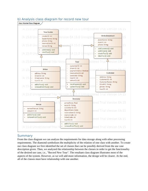
b) Analysis class diagram for record new tour
Summary
From the class diagram we can analyze the requirements for data storage along with other processing
requirements. The diamond symbolizes the multiplicity of the relation of one class with another. To create
our class diagram we first identified the set of classes that can be possibly derived from the use case
description given. Then, we analyzed the relationship between the classes in order to get the functionality
of the desired use case, i.e., "Record New Tour". The resultant class diagram illustrates most of the
aspects of the system. However, as we will add more information, the design will be clearer. At the end,
all of the classes must have relationship with one another.
Communication Diagram
a) Definition
Communication Diagram are used to explain the interaction of entities within a system that together
creates a behavior which cannot be done by the single entity itself. Communication Diagram can be
understand better with the example of a car, which can be broken down into several parts. These parts can
be integrated together to create various subsystems of the car such as, the brake system, transmission,
engine and so on. This distinct parts of the car can be assumed as classes which have distinct functions
and attributes. The distinct parts of the subsystem, say engine, can communicate with one another that is
they collaborate to make the engine work when the accelerator is forced by the driver. Thus
understanding the communication of the various subsystem is essentials to develop a better system. These
understanding is made easy with the help of communication diagram. A communication diagram also
known previously as a collaboration diagram (in version UML 1.x). There are three parts in the
communication diagram itself, these are: object also known as participants, communication links, and
messages which are passed through these links (Samuel, Mall & Kanth 2007).
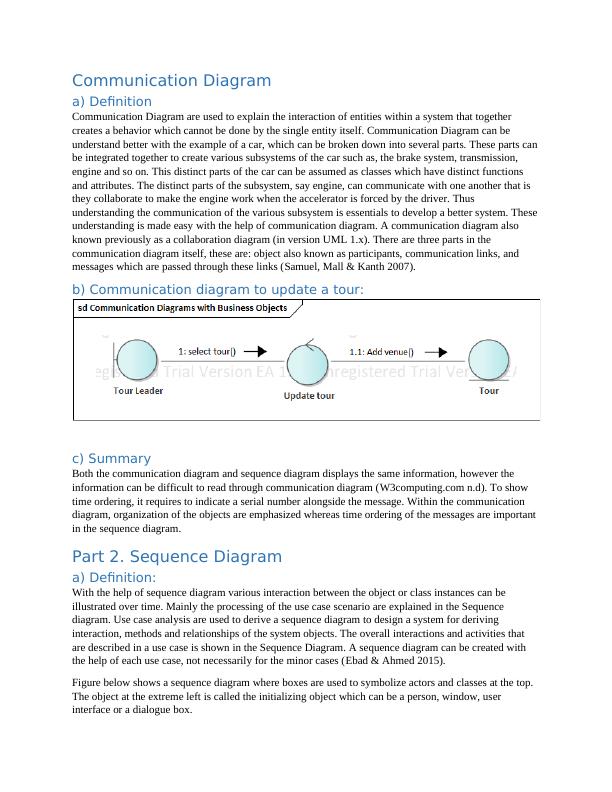
b) Communication diagram to update a tour:
c) Summary
Both the communication diagram and sequence diagram displays the same information, however the
information can be difficult to read through communication diagram (W3computing.com n.d). To show
time ordering, it requires to indicate a serial number alongside the message. Within the communication
diagram, organization of the objects are emphasized whereas time ordering of the messages are important
in the sequence diagram.
Part 2. Sequence Diagram
a) Definition:
With the help of sequence diagram various interaction between the object or class instances can be
illustrated over time. Mainly the processing of the use case scenario are explained in the Sequence
diagram. Use case analysis are used to derive a sequence diagram to design a system for deriving
interaction, methods and relationships of the system objects. The overall interactions and activities that
are described in a use case is shown in the Sequence Diagram. A sequence diagram can be created with
the help of each use case, not necessarily for the minor cases (Ebad & Ahmed 2015).
Figure below shows a sequence diagram where boxes are used to symbolize actors and classes at the top.
The object at the extreme left is called the initializing object which can be a person, window, user
interface or a dialogue box.
a) Definition
Communication Diagram are used to explain the interaction of entities within a system that together
creates a behavior which cannot be done by the single entity itself. Communication Diagram can be
understand better with the example of a car, which can be broken down into several parts. These parts can
be integrated together to create various subsystems of the car such as, the brake system, transmission,
engine and so on. This distinct parts of the car can be assumed as classes which have distinct functions
and attributes. The distinct parts of the subsystem, say engine, can communicate with one another that is
they collaborate to make the engine work when the accelerator is forced by the driver. Thus
understanding the communication of the various subsystem is essentials to develop a better system. These
understanding is made easy with the help of communication diagram. A communication diagram also
known previously as a collaboration diagram (in version UML 1.x). There are three parts in the
communication diagram itself, these are: object also known as participants, communication links, and
messages which are passed through these links (Samuel, Mall & Kanth 2007).
b) Communication diagram to update a tour:
c) Summary
Both the communication diagram and sequence diagram displays the same information, however the
information can be difficult to read through communication diagram (W3computing.com n.d). To show
time ordering, it requires to indicate a serial number alongside the message. Within the communication
diagram, organization of the objects are emphasized whereas time ordering of the messages are important
in the sequence diagram.
Part 2. Sequence Diagram
a) Definition:
With the help of sequence diagram various interaction between the object or class instances can be
illustrated over time. Mainly the processing of the use case scenario are explained in the Sequence
diagram. Use case analysis are used to derive a sequence diagram to design a system for deriving
interaction, methods and relationships of the system objects. The overall interactions and activities that
are described in a use case is shown in the Sequence Diagram. A sequence diagram can be created with
the help of each use case, not necessarily for the minor cases (Ebad & Ahmed 2015).
Figure below shows a sequence diagram where boxes are used to symbolize actors and classes at the top.
The object at the extreme left is called the initializing object which can be a person, window, user
interface or a dialogue box.
End of preview
Want to access all the pages? Upload your documents or become a member.
Related Documents
Enterprise Architect Designinglg...
|13
|2260
|26
System Analysis and Designlg...
|10
|2132
|197
IMAT5205 Structural And Behavioral Diagramslg...
|13
|2182
|25
UML Diagrams for Record New Tour Use Case - Deskliblg...
|10
|2321
|475
System Analysis and Designlg...
|11
|2198
|489
System Analysis and Designlg...
|9
|1852
|295