SBM4201 - System Analysis and Design: Gymnasium Management System
VerifiedAdded on 2023/04/21
|15
|2387
|424
Case Study
AI Summary
This case study provides a comprehensive analysis and design of a membership and facility management system for a gymnasium. It covers the six core processes of the Software Development Life Cycle (SDLC), including planning, requirement gathering and analysis, design, implementation, testing, and deployment. The design phase includes a detailed class diagram illustrating attributes, custom methods, relationships, and multiplicities, as well as use case diagrams modeling actors and use cases for staff roster scheduling and member registration. A PERT/CPM chart is also presented for project management. This document, available on Desklib, serves as a valuable resource for students studying system analysis and design.

Running head: SYSTEM ANALYSIS AND DESIGN
System Analysis and Design
Name of the Student
Name of the University
Author’s note:
System Analysis and Design
Name of the Student
Name of the University
Author’s note:
Paraphrase This Document
Need a fresh take? Get an instant paraphrase of this document with our AI Paraphraser
1SYSTEM ANALYSIS AND DESIGN
Table of Contents
Task 1: Six Core Process of SDLC..................................................................................................2
1.1 Planning:................................................................................................................................2
1.2 Requirement Gathering and Analysis:...................................................................................3
1.3 Design Phase:.........................................................................................................................4
1.4 Implementation Phase:...........................................................................................................5
1.5 Testing Phase:........................................................................................................................5
1.6 Deployment Phase:................................................................................................................5
Task 2: A Class Diagram:................................................................................................................6
Task 3: Use Case Diagram for Roster Scheduling..........................................................................7
Task 4: Use Case of Member Registration......................................................................................8
Task 5: PERT/CPM Chart...............................................................................................................9
Bibliography:.................................................................................................................................14
2SYSTEM ANALYSIS AND DESIGN
Task 1: Six Core Process of SDLC
SDLC or Software Development Lifecycle is referred to the foundation for all the
available software development methodologies. In Software Development Lifecycle, various
activities are associated with each phase. The phases are the primary division of a methodology
that refers to a specific objective of the project. There are total six phases in a conventional
Software Development Lifecycle. The Software Development Lifecycle is initiated by creating
plan for arranging the complete development until the system is live. The phases of the Software
Development Lifecycle are planning, requirement gathering and analysis, designing of the
system, actual development of the system, testing the developed code and finally deploying the
system in organization environment.
1.1 Planning:
The project aim and objective determination is done in the planning phase of Software
Development Lifecycle. The high level plan for the project include the budget and schedule of
the project. The planning is essential for a project management because it can guide the every
step taken in the project toward achieving the objectives. In the first step of planning phase, the
team members of the project will be selected. After that meetings will be conducted between
project team and stakeholders. In this meetings, the team ad stakeholder will create a list of
project requirements and scope. After the requirements are clear, the subsystems of the project
will be identified and agreed upon by both the team and stakeholders. Now, the project manager
will create a budget and schedule of the project. This schedule and budget will be communicated
with the stakeholders for verification. The budget and schedule can be changed by the project
manager in case stakeholder ask for change. After that team members will be assigned to each
⊘ This is a preview!⊘
Do you want full access?
Subscribe today to unlock all pages.

Trusted by 1+ million students worldwide

3SYSTEM ANALYSIS AND DESIGN
activity of the Software Development Lifecycle. At last one meeting with the stakeholders will
be done for confirming all the outcome of the planning phase.
1.2 Requirement Gathering and Analysis:
The requirement gathering and analysis is done by the system analyst and business
analyst. The business analyst is responsible for collecting the business related data. Various
information gathering techniques are conducted for gathering the business and system
requirements. Another requirement that is essential for making the system user centric is user
requirement. The information gathering techniques used in the project are interview,
questionnaire and document analysis. The business analyst conduct the interview with the few
selective personnel of Body Sculptors Gymnasium. In the interview process, the interviewer
conducts face-to-face meeting with the participant. The advantage of interview is that,
interviewer can verify the integrity of collected data. However, as the interview process is time
consuming and costly, the interview will be done in small scale. The business analyst will create
questionnaire for all the departments and external entities of Body Sculptors Gymnasium. All the
participants will be informed of a deadline for submitting the questions. In order to do the
document analysis, the business analyst will be assigned a helper. The assistant is a staff of Body
Sculptors Gymnasium.
The business analyst provides the collected data to the system analyst for further analysis.
The system analyst then perform various analysis on the data and generate system requirements.
The requirements are of two types such as functional and non-functional. The functional
requirements describe the processes that will be done by the system. The non-functional
requirements describes how the system will support all the processes.
Paraphrase This Document
Need a fresh take? Get an instant paraphrase of this document with our AI Paraphraser
4SYSTEM ANALYSIS AND DESIGN
1.3 Design Phase:
In the design phase, descried outcome from the system and functions are presented
through graphical diagrams. The first step in the design phase is creating the architecture of the
system. The architecture of the system is the blueprint of the Body Sculptors Gymnasium
system. Based on the architecture, the designers will design the modules and data requirements
of system. The UML or Unified Modeling Language design is the base of all the designs. It is
because UML diagrams are capable of capturing both the static and dynamic nature of the
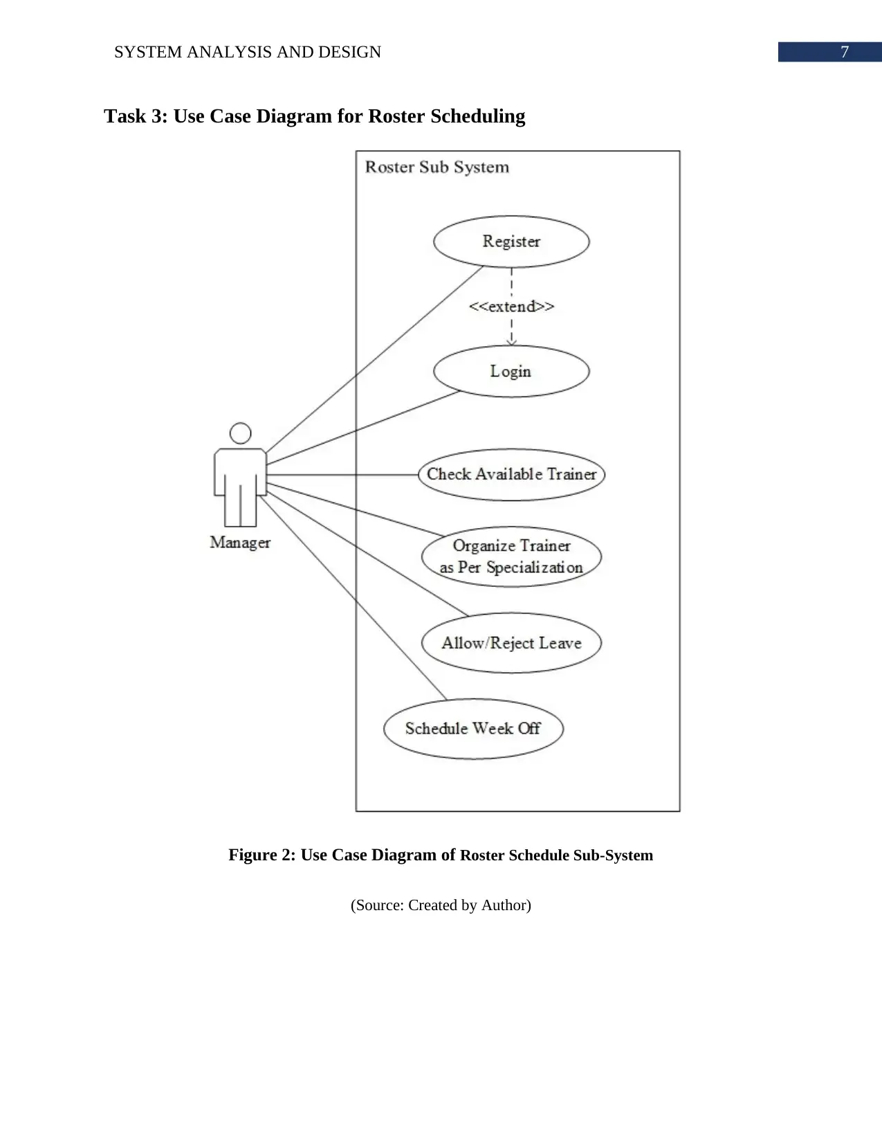
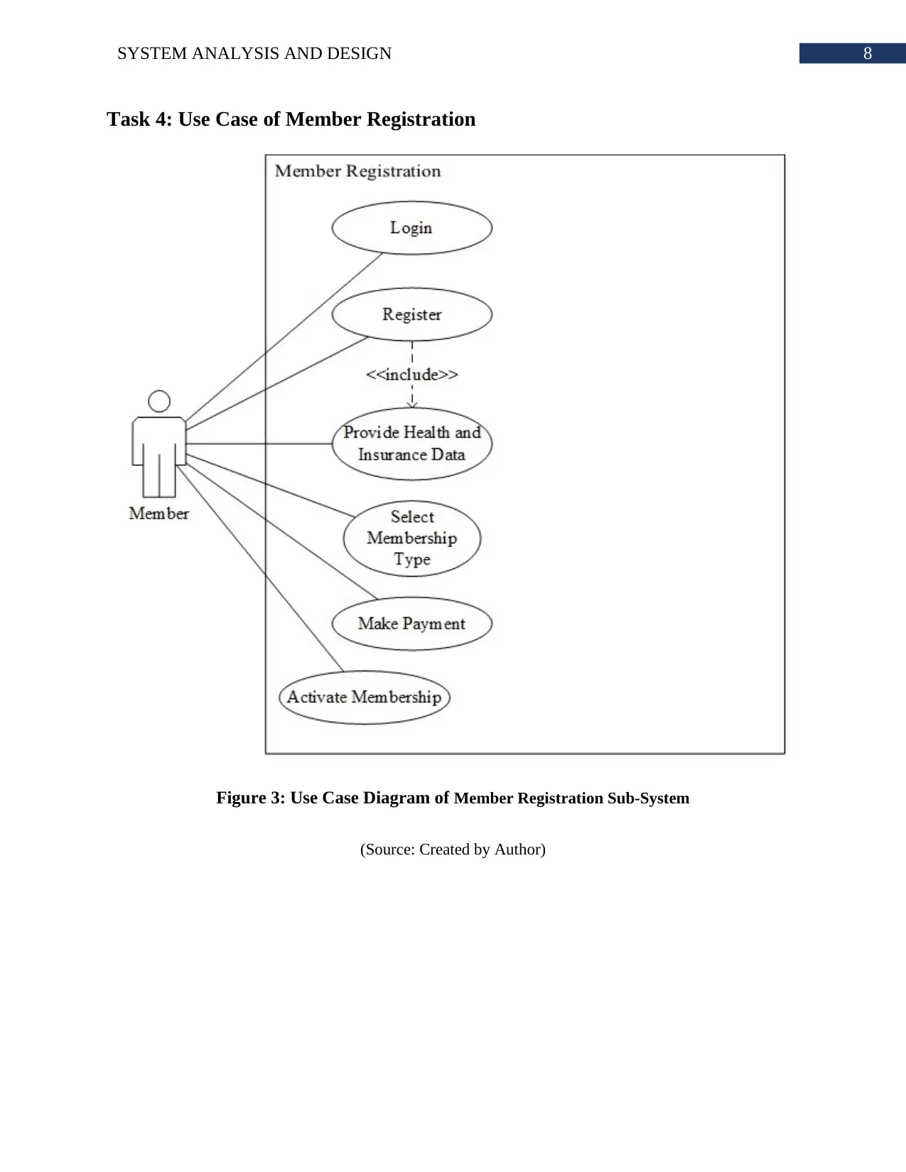
system. The use case diagram will provide an insight of how the end users of the system will
interact with the system. This data can be used for determining specific functions of the system
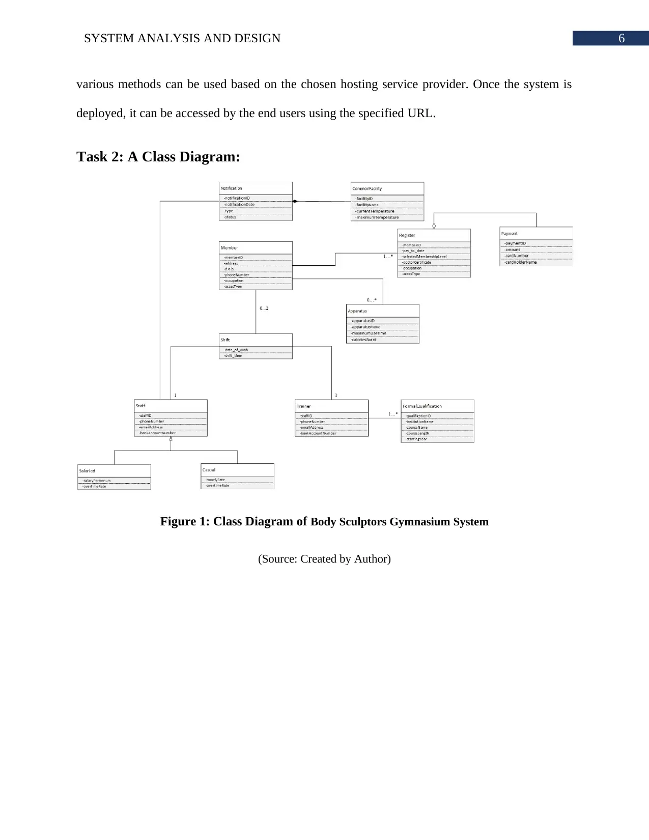
along with the interface design. The class diagram, on the other hand, captures the data
requirements and modules of the system. It is essential to note that UML diagram application is
not limited to object oriented methodology based system. After the basic diagrams are created,
the data models are created. The data model includes, ER diagram, schema diagram, data flow
diagram and many more.
The next designs are done by the user interface designers. The first step to design the
interface is creating mockups of the system. As the mockups are easy to implement and change,
these mockups are used for getting user verification. After the mockups are finalized, the user
interfaces are created. The mockups are low fidelity prototypes and user interfaces are high
fidelity prototypes. In some cases, the few system components are implemented in local servers.
Then a network designer is hired for creating the network design that can support proper
communication between the end user and system. Such an example can be seen if organization
wants to implement a new network within it.
5SYSTEM ANALYSIS AND DESIGN
1.4 Implementation Phase:
Implementation phase refers to all the activities that is related to write codes and
developing a functional system. In this phase, the interface and database are designed
simultaneously. The user interface is designed based on the high fidelity prototypes developed in
the previous phase. HTML, CSS and JavaScript is used for creating the actual interface. As the
system will include many animations and hover effects, many interface design related decisions
will be taken during the development. MVC structure of a system is the current trend in the web
based system development. The MVC allows web applications to be very fast and dynamic. On
the other hand, the database will be done based on the most compatible platform with the web
platform. The network is implemented in the Body Sculptors Gymnasium physically. The
network include routers, firewall, switches, server, PC and other server devices.
1.5 Testing Phase:
The first testing activity is done the developers. They manually check the bugs in the
developed code to eliminate the loopholes. Debugging allows the development team to prevent
minimum errors in the code that are glitches, false response and many others. The functionality
of the system without concerning about internal structure is done using the Blackbox testing. In
order test the internal structure of the database, the white box testing is done.
1.6 Deployment Phase:
The deployment phase is done under the supervision of project manager. The website is
deployed in a hosting website. A SLA or Service Level Agreement is signed by the host and
organization owner. There are various hosting services available in the internet. The project
manager will chose few of those and evaluate the efficiency and affectivity of each hosting
services. A financial and technical feasibility analysis is also done. To deploy the website,
⊘ This is a preview!⊘
Do you want full access?
Subscribe today to unlock all pages.

Trusted by 1+ million students worldwide
6SYSTEM ANALYSIS AND DESIGN
various methods can be used based on the chosen hosting service provider. Once the system is
deployed, it can be accessed by the end users using the specified URL.
Task 2: A Class Diagram:
Figure 1: Class Diagram of Body Sculptors Gymnasium System
(Source: Created by Author)
various methods can be used based on the chosen hosting service provider. Once the system is
deployed, it can be accessed by the end users using the specified URL.
Task 2: A Class Diagram:
Figure 1: Class Diagram of Body Sculptors Gymnasium System
(Source: Created by Author)
Paraphrase This Document
Need a fresh take? Get an instant paraphrase of this document with our AI Paraphraser
7SYSTEM ANALYSIS AND DESIGN
Task 3: Use Case Diagram for Roster Scheduling
Figure 2: Use Case Diagram of Roster Schedule Sub-System
(Source: Created by Author)
Task 3: Use Case Diagram for Roster Scheduling
Figure 2: Use Case Diagram of Roster Schedule Sub-System
(Source: Created by Author)
8SYSTEM ANALYSIS AND DESIGN
Task 4: Use Case of Member Registration
Figure 3: Use Case Diagram of Member Registration Sub-System
(Source: Created by Author)
Task 4: Use Case of Member Registration
Figure 3: Use Case Diagram of Member Registration Sub-System
(Source: Created by Author)
⊘ This is a preview!⊘
Do you want full access?
Subscribe today to unlock all pages.

Trusted by 1+ million students worldwide
9SYSTEM ANALYSIS AND DESIGN
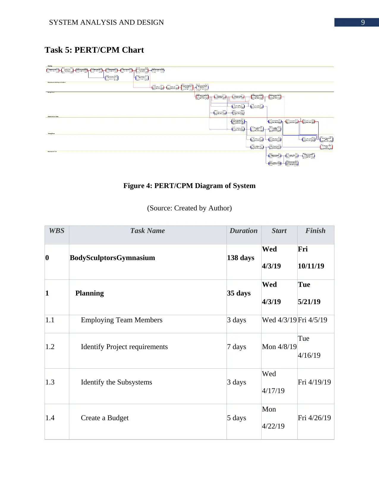
Task 5: PERT/CPM Chart
Figure 4: PERT/CPM Diagram of System
(Source: Created by Author)
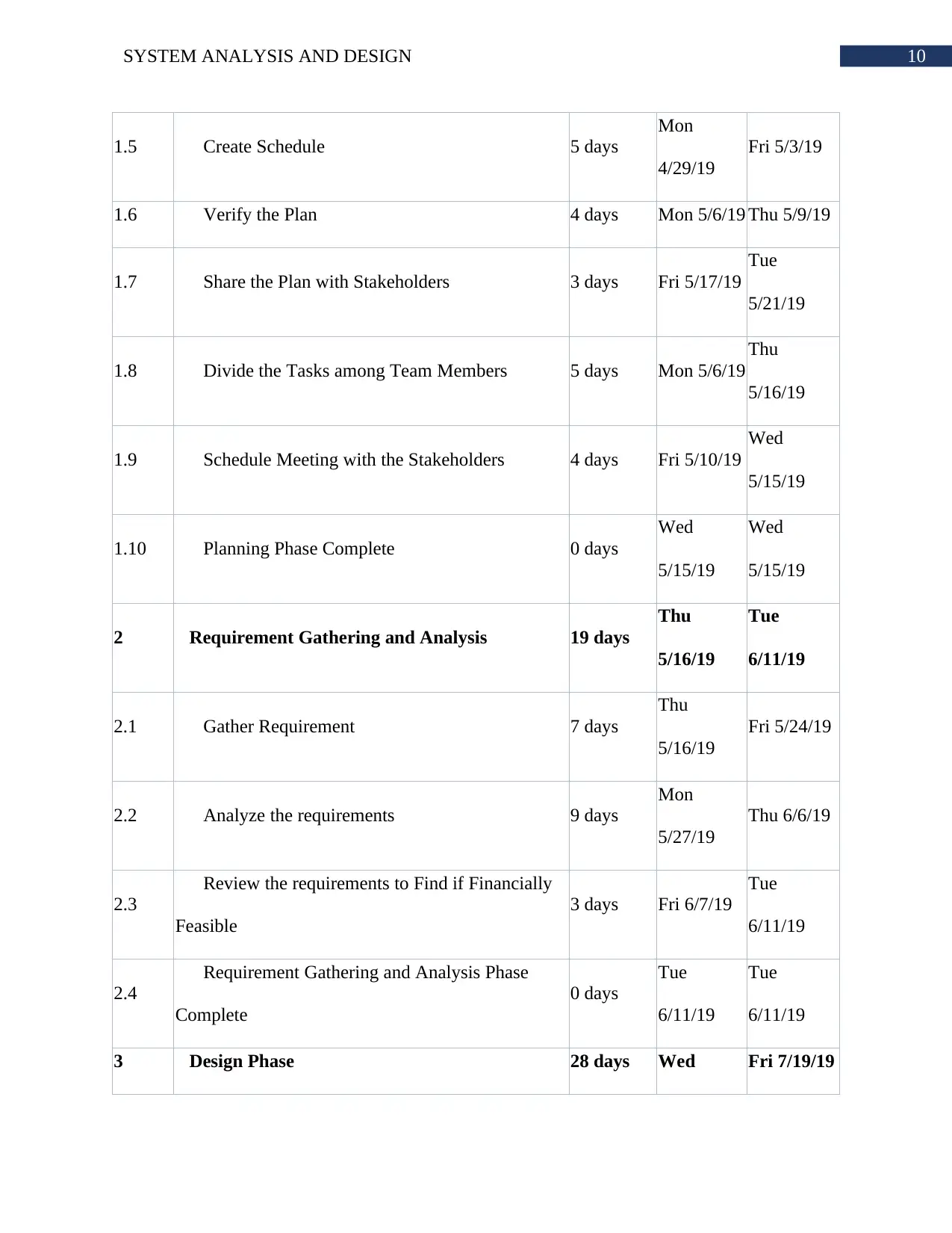
WBS Task Name Duration Start Finish
0 BodySculptorsGymnasium 138 days
Wed
4/3/19
Fri
10/11/19
1 Planning 35 days
Wed
4/3/19
Tue
5/21/19
1.1 Employing Team Members 3 days Wed 4/3/19 Fri 4/5/19
1.2 Identify Project requirements 7 days Mon 4/8/19
Tue
4/16/19
1.3 Identify the Subsystems 3 days
Wed
4/17/19
Fri 4/19/19
1.4 Create a Budget 5 days
Mon
4/22/19
Fri 4/26/19
Paraphrase This Document
Need a fresh take? Get an instant paraphrase of this document with our AI Paraphraser
10SYSTEM ANALYSIS AND DESIGN
1.5 Create Schedule 5 days
Mon
4/29/19
Fri 5/3/19
1.6 Verify the Plan 4 days Mon 5/6/19 Thu 5/9/19
1.7 Share the Plan with Stakeholders 3 days Fri 5/17/19
Tue
5/21/19
1.8 Divide the Tasks among Team Members 5 days Mon 5/6/19
Thu
5/16/19
1.9 Schedule Meeting with the Stakeholders 4 days Fri 5/10/19
Wed
5/15/19
1.10 Planning Phase Complete 0 days
Wed
5/15/19
Wed
5/15/19
2 Requirement Gathering and Analysis 19 days
Thu
5/16/19
Tue
6/11/19
2.1 Gather Requirement 7 days
Thu
5/16/19
Fri 5/24/19
2.2 Analyze the requirements 9 days
Mon
5/27/19
Thu 6/6/19
2.3
Review the requirements to Find if Financially
Feasible
3 days Fri 6/7/19
Tue
6/11/19
2.4
Requirement Gathering and Analysis Phase
Complete
0 days
Tue
6/11/19
Tue
6/11/19
3 Design Phase 28 days Wed Fri 7/19/19
11SYSTEM ANALYSIS AND DESIGN
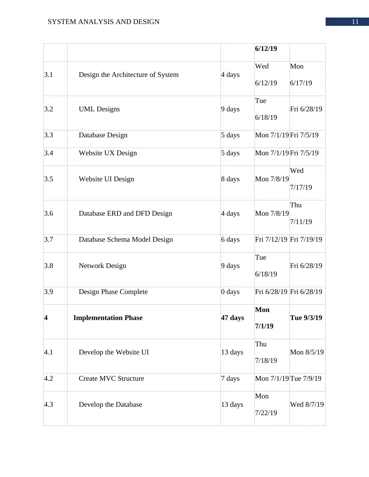
6/12/19
3.1 Design the Architecture of System 4 days
Wed
6/12/19
Mon
6/17/19
3.2 UML Designs 9 days
Tue
6/18/19
Fri 6/28/19
3.3 Database Design 5 days Mon 7/1/19 Fri 7/5/19
3.4 Website UX Design 5 days Mon 7/1/19 Fri 7/5/19
3.5 Website UI Design 8 days Mon 7/8/19
Wed
7/17/19
3.6 Database ERD and DFD Design 4 days Mon 7/8/19
Thu
7/11/19
3.7 Database Schema Model Design 6 days Fri 7/12/19 Fri 7/19/19
3.8 Network Design 9 days
Tue
6/18/19
Fri 6/28/19
3.9 Design Phase Complete 0 days Fri 6/28/19 Fri 6/28/19
4 Implementation Phase 47 days
Mon
7/1/19
Tue 9/3/19
4.1 Develop the Website UI 13 days
Thu
7/18/19
Mon 8/5/19
4.2 Create MVC Structure 7 days Mon 7/1/19 Tue 7/9/19
4.3 Develop the Database 13 days
Mon
7/22/19
Wed 8/7/19
6/12/19
3.1 Design the Architecture of System 4 days
Wed
6/12/19
Mon
6/17/19
3.2 UML Designs 9 days
Tue
6/18/19
Fri 6/28/19
3.3 Database Design 5 days Mon 7/1/19 Fri 7/5/19
3.4 Website UX Design 5 days Mon 7/1/19 Fri 7/5/19
3.5 Website UI Design 8 days Mon 7/8/19
Wed
7/17/19
3.6 Database ERD and DFD Design 4 days Mon 7/8/19
Thu
7/11/19
3.7 Database Schema Model Design 6 days Fri 7/12/19 Fri 7/19/19
3.8 Network Design 9 days
Tue
6/18/19
Fri 6/28/19
3.9 Design Phase Complete 0 days Fri 6/28/19 Fri 6/28/19
4 Implementation Phase 47 days
Mon
7/1/19
Tue 9/3/19
4.1 Develop the Website UI 13 days
Thu
7/18/19
Mon 8/5/19
4.2 Create MVC Structure 7 days Mon 7/1/19 Tue 7/9/19
4.3 Develop the Database 13 days
Mon
7/22/19
Wed 8/7/19
⊘ This is a preview!⊘
Do you want full access?
Subscribe today to unlock all pages.

Trusted by 1+ million students worldwide
1 out of 15
Related Documents
Your All-in-One AI-Powered Toolkit for Academic Success.
+13062052269
info@desklib.com
Available 24*7 on WhatsApp / Email
![[object Object]](/_next/static/media/star-bottom.7253800d.svg)
Unlock your academic potential
Copyright © 2020–2025 A2Z Services. All Rights Reserved. Developed and managed by ZUCOL.


