System Analysis and Design

Verified

Added on  2023/04/21

|10
|1954
|331
AI Summary
This document provides an overview of system analysis and design, focusing on use case realisation, analysis class diagram, communication diagram, and sequence diagram. It also discusses the evaluation process and the use of CASE tools and UML diagrams. The document offers insights into the importance of these tools in the development and maintenance of robust systems.

Contribute Materials

Your contribution can guide someone’s learning journey. Share your documents today.
Document Page
Running head: SYSTEM ANALYSIS AND DESIGN
System Analysis and Design
Name of the Student
Name of the University
Author’s note:

Secure Best Marks with AI Grader

Need help grading? Try our AI Grader for instant feedback on your assignments.
Document Page
1SYSTEM ANALYSIS AND DESIGN
Table of Contents
Part 1: Use Case Realisation for the ‘Record New Tour’ Use Case...........................................2
1.1 Analysis Class Diagram:..................................................................................................2
1.2 Communication Diagram:................................................................................................3
Part 2: Sequence Diagram..........................................................................................................5
Part 3: Evaluation.......................................................................................................................6
Bibliography:..............................................................................................................................9
Document Page
2SYSTEM ANALYSIS AND DESIGN
Part 1: Use Case Realisation for the ‘Record New Tour’ Use Case
1.1 Analysis Class Diagram:
Based on the definition mentioned in software engineering, the class diagram can be
considered as the static Unified Modelling Language of a system or an application that
represents the classes itself and its elements. The class diagram not only represent classes but
it also shows the relation between classes.
The class diagram can be useful in system analysis and design through the following
ways.
i. It can save a lot of time of the system analyst and designers by just allowing
analysis of each class from its attributes to its relation with other classes
ii. For the TMS or any other system, it can be the perfect tool for showing the
static classifier
Figure 1: Class Diagram of Wide World Tour Management System
(Source: Created by Author)
Document Page
3SYSTEM ANALYSIS AND DESIGN
As it can be seen in the figure 1, the designed class diagram has four classes. Every
one of this classes has its unique identify and features. The client and leader classes has been
included additionally to justify the case study and the nature of the proposed TMS
application. The client class shows the attributes and operations of the classes. Each of these
attributes are capable of capturing individual important information of the TMS’s clients. The
tour class is the centre class that is connected to all the other classes. It is very important to
notice that tour class has connected all these classes together and yet it has not been affected
by any of these classes. It has normal association relationship all the classes. It was also
possible to show that the driver and leader has composition relation but it would not have
been completely right from the real world point of view.
1.2 Communication Diagram:
The communication diagram is also popular as the collaboration diagram. It is a kind
of interaction diagram. This diagram imagines the interaction between the objects of the
frameworks. This is an all-encompassing piece of the object diagram which envisions the
framework objects alongside the framework messages which is exchanged among the objects.
The communication diagram can be useful in system analysis and design through the
following ways.
i. Showing the functions of every use is a crucial part of system analysis and
design. The communication diagram perfectly visualizes these functionalities
ii. The communication among the objects allows understanding the basic
requirements of the dynamic structure

Secure Best Marks with AI Grader

Need help grading? Try our AI Grader for instant feedback on your assignments.
Document Page
4SYSTEM ANALYSIS AND DESIGN
Figure 2: Communication Diagram of Wide World Tour Management System
(Source: Created by Author)
The rectangles have been utilized for imagining the objects that speaks to each class
in the class diagram. The lines among the class examples are utilized to picture the
relationship among a few sections of the system. The message transmission between the
objects has been appeared through bolts. The correspondence diagram has four objects. As
the class diagram has four classes, for every one of the classes, one object is made. The
tourSearch message will be the first to introduce visit record choice. After the client chooses
a visit from the query output, the tourBook message is instated. This message is the done as a
circle. Assume, the visit will have more than one driver, at that point this message will run a
few times and begin the assignToTour message. Every one of these objects has the
fundamental thought of the classes characterized in the class diagram.
Document Page
5SYSTEM ANALYSIS AND DESIGN
Part 2: Sequence Diagram
One of the for the most part utilized unique displaying arrangements is Sequence
Diagram. The sequence diagram for the most part focus on the helps of classes. The sequence
diagram additionally think about the activities and objects as the vital factor of TMS system.
It is a sort of interaction diagram. This diagram depicts how the arrangement of objects
cooperate.
The communication diagram can be useful in system analysis and design through the
following ways.
i. The sequence diagram can be used for designing the collaboration as analysts
can utilize it as collaboration tool
ii. The sequence diagram supports various levels of dynamic behaviour and
structure of a system in a perfect manner.
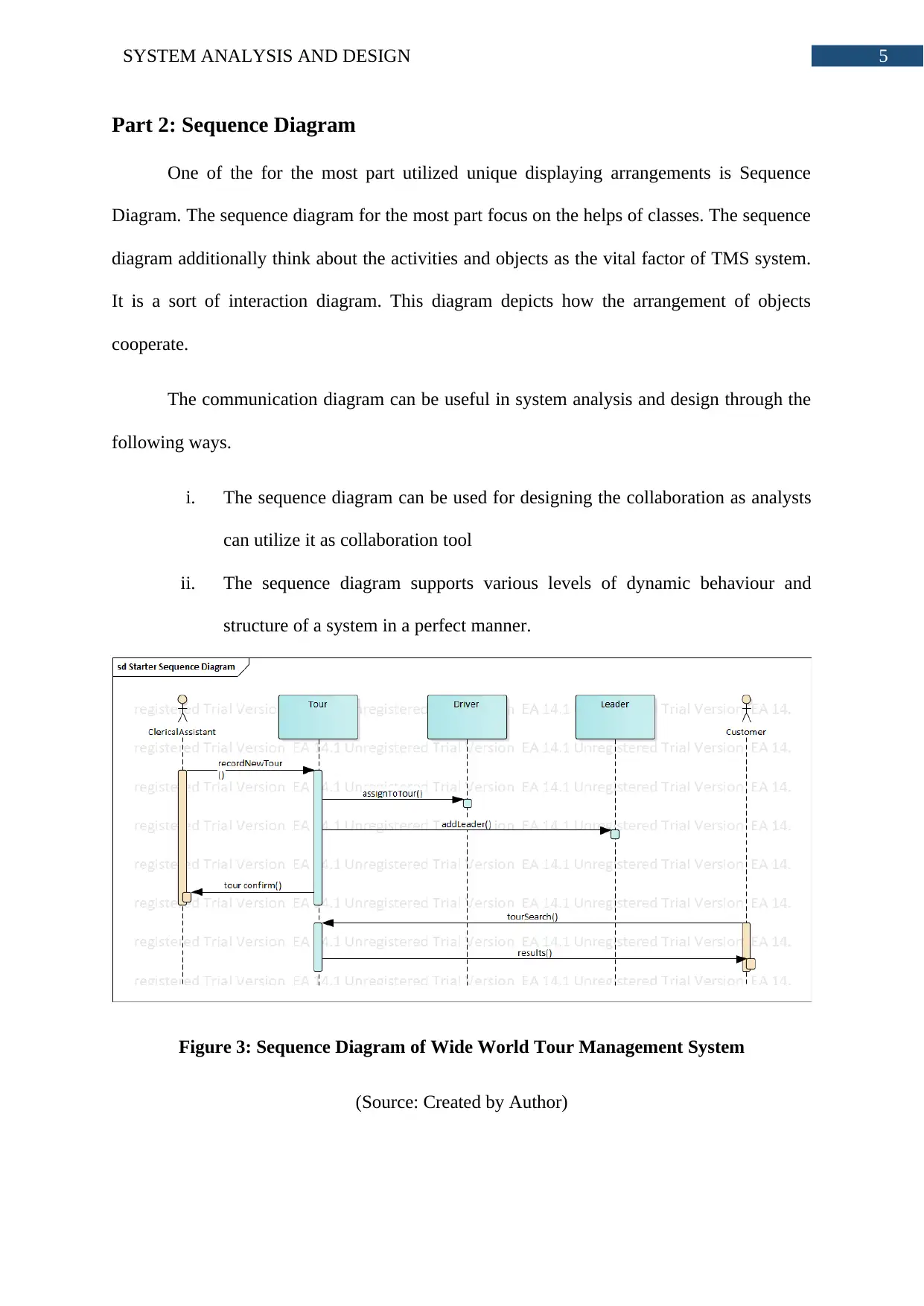
Figure 3: Sequence Diagram of Wide World Tour Management System
(Source: Created by Author)
Document Page
6SYSTEM ANALYSIS AND DESIGN
The proposed sequence diagram has add up to five sections. The client is the
performer who starts the procedure. It is accepted that the application will demonstrate the
query output each time the client calls the searchTour technique. In view of the outcome, the
client chooses a tour and affirm that tour. The tour object calls the tourBook technique which
affirms the tour. The tour object calls the driver and pioneer classes through the
assignToTour and addLeader strategies separately. The last component is the database. The
applications stores the client, tour, relegated driver and pioneer to the database. After the
putting away to the database is affirmed, the application answers to the client that tour is
reserved. It is accepted that every one of the techniques' rationale are identified with the
tourBook strategy. Amid the advancement of this sequence diagram it is likewise expected
that the information will be spared to the database simply after every one of the techniques
are finished effectively.
Part 3: Evaluation
The ICT projects are completed and managed through various tools that can make the
project related tasks very easy. The CASE tool is used for the purpose of making the project
activities more efficient. The Enterprise Architect has an integrated modelling platform that
supports the complete lifecycle of IT and business systems, System and Software engineering
and embedded and real-time development. The EA has built-in requirement management
capabilities that assisted in tracing the high level system specifications to evaluation, design,
development, testing and maintaining the three models that have been created in this
assignment. The EA provides the opportunity for developing maintainable and robust
systems. It was possible to share the vision of the system accurately and easily because of the
high-quality built-in documentation and reporting. The EA shows some really high
performance capabilities. The module loading time of this CASE tool is comparatively less
than similar case tools. It is agreed by all the users and it was established also during the

Paraphrase This Document

Need a fresh take? Get an instant paraphrase of this document with our AI Paraphraser
Document Page
7SYSTEM ANALYSIS AND DESIGN
system design part of this assignment that enterprise architect is a really fast performing piece
of technology that can load large modules in seconds. It features a high-performing model
repository so that teams can share the same enterprise view. The collaboration is another big
factor in this enterprise architect tool. The team members who are separated by countries can
communicate easily through deployable cloud servers implemented with tightly integrated
version control ability of the system.
It was really important to focus during the development of the system designs that
complete traceability is provided by the CASE tool Enterprise Architect. The Case tool not
only supported in offering full traceability from design, but also it offered complete
traceability in terms of requirements and analysis of those requirements. As the task was
about only designing, this traceability was observed to be available for this task only. It is not
tested whether this feature remains of same quality from development to deployment. It also
has the features like verifying, validating and analysing the impact of the diagrams which
assisted in designing the accurate diagrams. The enterprise architect was equipped with the
correct information which assisted a lot in understanding and analysing the requirements. All
the features needed to deliver a task perfectly is available in the enterprise architecture.
The essential help that the system analyst will get from the case tool is finished
spotlight on the design of the proposed application as opposed to worried about the codes.
The undertaking engineering case tool enables simple procedure to incorporate new
prerequisites into the 'include new tour' use case. The analyst could concentrate on the
structuring of the UML diagrams instead of agonizing over how to use the case tool. This was
imperative as the originators had more opportunity to break down and structure the diagrams
than finding out about the venture design. The EA tool case has a simple to use user
connection module that empowers making the diagrams effectively. Making the class
diagram was simple and the last diagram was exact. Including the qualities and characterizing
Document Page
8SYSTEM ANALYSIS AND DESIGN
the tasks was simple. The case tool gives simple changes. The case tool additionally give
simple to create interface to segment diagram and grouping diagram. It bolsters every one of
the components of the UML diagrams. Each of the diagrams were made precisely so that the
basic and dynamic parts of the framework can be caught consummately. It gave ideal
situation to catching and planning the bits of knowledge of the business procedure of record
new tour use case.
The biggest support of the UML to the system analyst or designer is that it allows
capturing the dynamic and static, both views of the system. The static structure of an
application is its basic requirements and around it the whole application is developed and
runs. On the other hand, the dynamic behaviour of the application states how the static
structures are processed to change internal states and make the system run. As system analyst
or designer, it is extremely important to remember that both of static and dynamic structure
together completes a system. The UML has fourteen kinds of diagrams that captures almost
all the aspects of an application and allows creating a perfect scenario for evaluating the
system accurately. The UML diagrams has class diagrams that capture the classes, attributes
and operation which are static elements of application and it also has sequence diagram that
show the broad and complex dynamic aspect of the system.
Document Page
9SYSTEM ANALYSIS AND DESIGN
Bibliography:
Afanasyev, A.N., Voit, N.N., Voevodin, E.Y. and Gainullin, R.F., 2015, October. Control of
UML diagrams in designing automated systems software. In Application of Information and
Communication Technologies (AICT), 2015 9th International Conference on (pp. 285-288).
IEEE.
Cunha, A., Garis, A. and Riesco, D., 2015. Translating between Alloy specifications and
UML class diagrams annotated with OCL. Software & Systems Modeling, 14(1), pp.5-25.
1 out of 10
circle_padding
hide_on_mobile
zoom_out_icon
[object Object]

Your All-in-One AI-Powered Toolkit for Academic Success.

Available 24*7 on WhatsApp / Email

[object Object]