SBM4201 System Analysis and Design Portfolio: Database and HMS Design
VerifiedAdded on 2023/03/23
|14
|1306
|36
Portfolio
AI Summary
This portfolio provides solutions for system analysis and design problems, focusing on two main scenarios: a customer database system and a hospital management system (HMS). For the customer database, it includes a work breakdown structure, duration calculations, and identification of the critical path. The HMS section details key entities, use cases (admission, appointment booking, ward bed booking), and system actors (billing, doctors, administrators, ward officers). It also covers software protection, licensing with class diagrams for employee-project relationships, and case studies like Training Inc., showcasing ERD, class, state machine, and sequence diagrams. Further tasks include activity diagrams, system architecture, user interface design, and testing/deployment strategies, emphasizing user-friendliness, search engine support, network maintenance, and compatibility with evolving technologies. The document concludes with a bibliography referencing relevant textbooks on system analysis and design.
Isaac.w
TEMAOS [Company address]
SYSTEM ANALYSIS AND DESIGN
TEMAOS [Company address]
SYSTEM ANALYSIS AND DESIGN
Paraphrase This Document
Need a fresh take? Get an instant paraphrase of this document with our AI Paraphraser
Question 1
Following the creation of a customer database, the following is a table showing the work
breakdown followed by the calculation of the duration dates of the same and the critical path.
Task Description Duration Predecessors
1 System design 5 days 0
2 Subsystem A design 5 days 1
3 Subsystem B design 4 days 2
4 Subsystem C design 5 days 3
5 Programming A
design
9 days 4
6 Programming B
design
5 days 5
7 Programming C
design
8 days 6
8 Testing 4 days 7
Calculations
Task Description Start date Finish date
1 System design 14th may 18th may
2 Subsystem A design 19th may 23nd may
3 Subsystem B design 24th may 27th may
4 Subsystem C design 28th may 1st June
5 Programming A
design
2nd June 10th June
6 Programming B
design
11th June 15th June
7 Programming C
design
16th June 23rd June
8 Testing 24th June 27th June
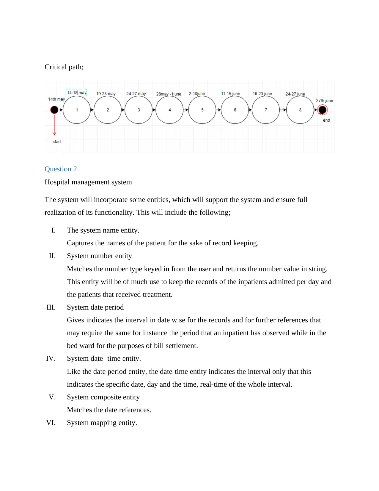
Critical path;
Question 2
Hospital management system
The system will incorporate some entities, which will support the system and ensure full
realization of its functionality. This will include the following;
I. The system name entity.
Captures the names of the patient for the sake of record keeping.
II. System number entity
Matches the number type keyed in from the user and returns the number value in string.
This entity will be of much use to keep the records of the inpatients admitted per day and
the patients that received treatment.
III. System date period
Gives indicates the interval in date wise for the records and for further references that
may require the same for instance the period that an inpatient has observed while in the
bed ward for the purposes of bill settlement.
IV. System date- time entity.
Like the date period entity, the date-time entity indicates the interval only that this
indicates the specific date, day and the time, real-time of the whole interval.
V. System composite entity
Matches the date references.
VI. System mapping entity.
⊘ This is a preview!⊘
Do you want full access?
Subscribe today to unlock all pages.

Trusted by 1+ million students worldwide
Indicates the amount of money together with the currency name. For instance, in the
indication of the charge of the total bill, it can either be in dollars or Euros, depending on
the currency preferred by the hospital management.
The use case being the processes that a patient has to undergo stage by stage and the actors being
the executors of the process, which can be either a human or a system. In the system use case and
actors scenario can be applicable in three cases;
Admission
Booking appointment
Booking a bed in the ward.
1. Use case admission.
This case involves the registration process and confirmation of details to proceed for
treatment. In this case, either the patient applies electronically or through a handwritten
form where he/she writes his /her personal information; the name, home address, gender,
contact, age and year of birth. The details in the form are then entered into the Hospital
management system database. This is done after a subscription fee for the form is paid
where now the administrator keys in the information including the date and time of
admission and the patient are issued with a card to proceeds to see the doctor.
2. Use case Appointment.
In this case, the patient is booking an appointment through hospital management. This
can be achieved through phone or upon arrival of the patient. The patient submits his/her
personal information and in return, the date is given and time to visit or see the doctor.
3. Use case ward bed.
It involves the patient confirmation from the doctor that the patient needs to stay for
treatment after which the bed is secured for the patient and a fee is paid for the same by
the patient and the information is transferred or updated in the management’s database.
The system actors being;
The billing system
The general doctor
Receptionist administrator
Paraphrase This Document
Need a fresh take? Get an instant paraphrase of this document with our AI Paraphraser
Ward officer
The inpatient and outpatient officers
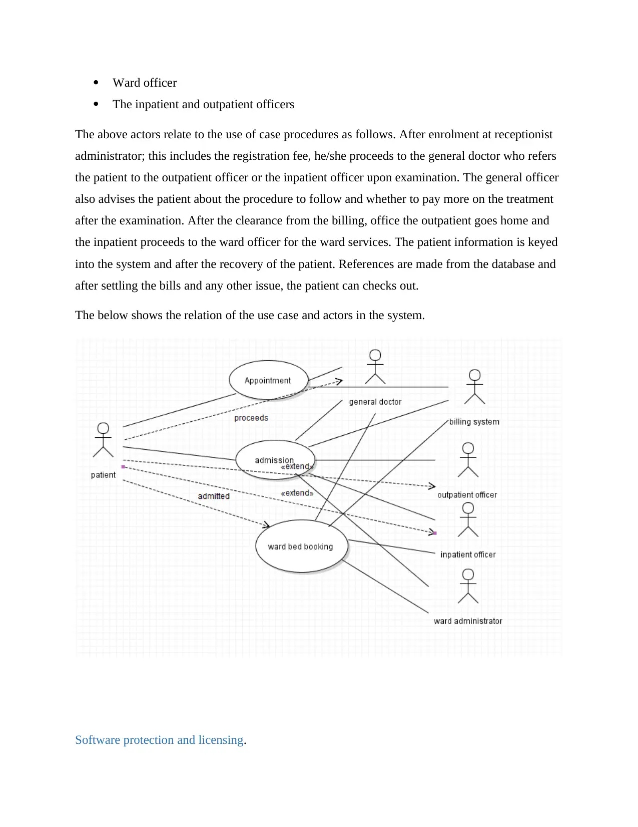
The above actors relate to the use of case procedures as follows. After enrolment at receptionist
administrator; this includes the registration fee, he/she proceeds to the general doctor who refers
the patient to the outpatient officer or the inpatient officer upon examination. The general officer
also advises the patient about the procedure to follow and whether to pay more on the treatment
after the examination. After the clearance from the billing, office the outpatient goes home and
the inpatient proceeds to the ward officer for the ward services. The patient information is keyed
into the system and after the recovery of the patient. References are made from the database and
after settling the bills and any other issue, the patient can checks out.
The below shows the relation of the use case and actors in the system.
Software protection and licensing.
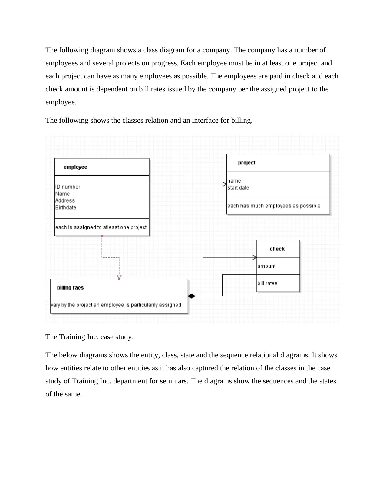
The following diagram shows a class diagram for a company. The company has a number of
employees and several projects on progress. Each employee must be in at least one project and
each project can have as many employees as possible. The employees are paid in check and each
check amount is dependent on bill rates issued by the company per the assigned project to the
employee.
The following shows the classes relation and an interface for billing.
The Training Inc. case study.
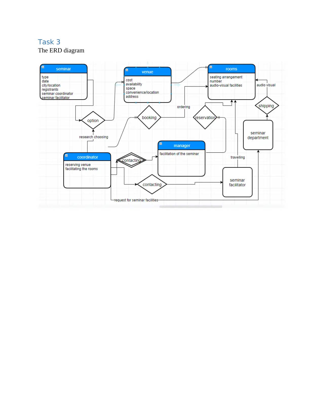
The below diagrams shows the entity, class, state and the sequence relational diagrams. It shows
how entities relate to other entities as it has also captured the relation of the classes in the case
study of Training Inc. department for seminars. The diagrams show the sequences and the states
of the same.
⊘ This is a preview!⊘
Do you want full access?
Subscribe today to unlock all pages.

Trusted by 1+ million students worldwide
Task 3
The ERD diagram
The ERD diagram
Paraphrase This Document
Need a fresh take? Get an instant paraphrase of this document with our AI Paraphraser
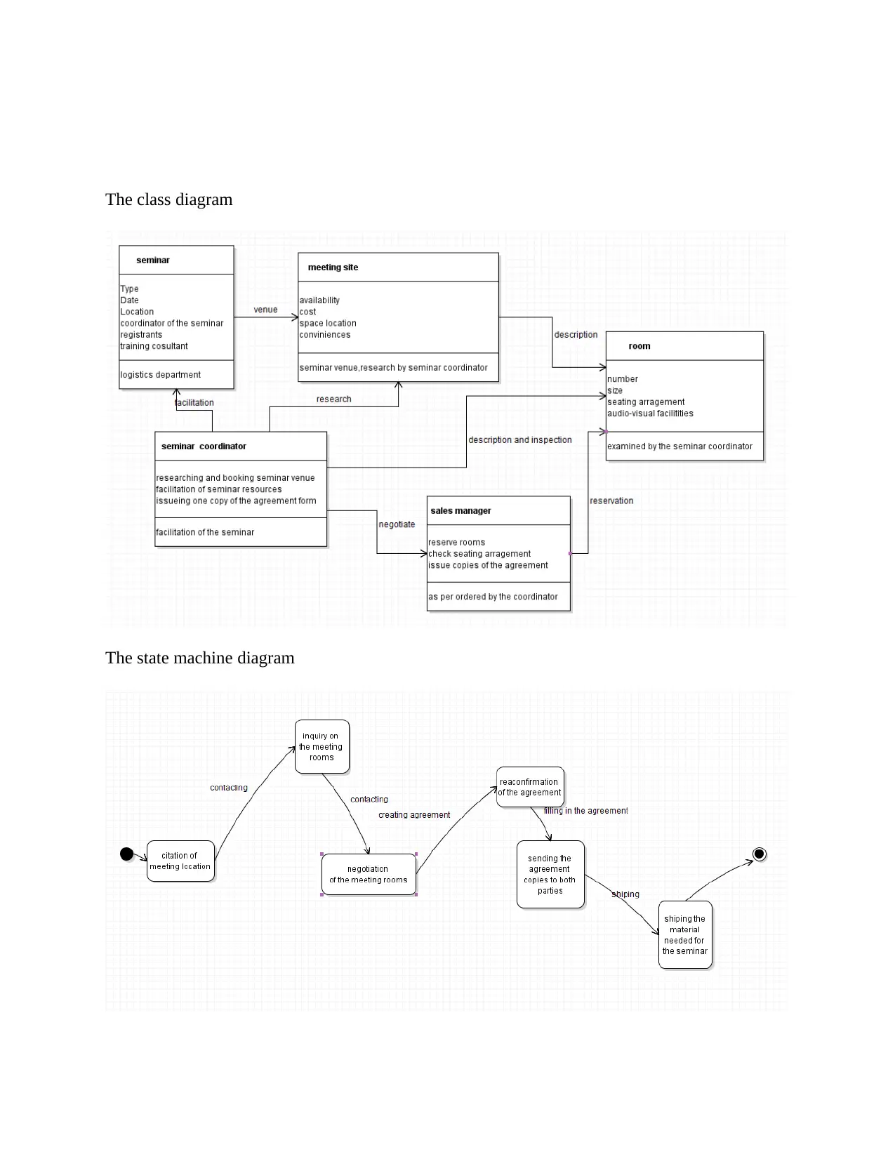
The class diagram
The state machine diagram
The state machine diagram
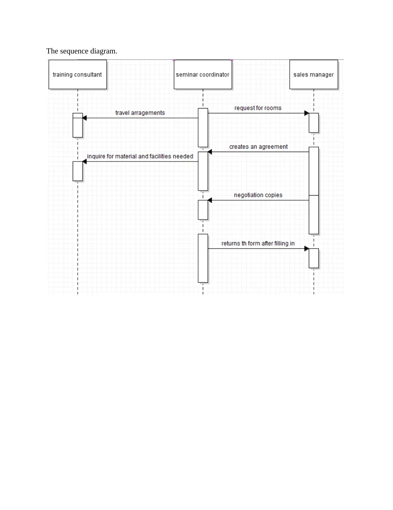
The sequence diagram.
⊘ This is a preview!⊘
Do you want full access?
Subscribe today to unlock all pages.

Trusted by 1+ million students worldwide
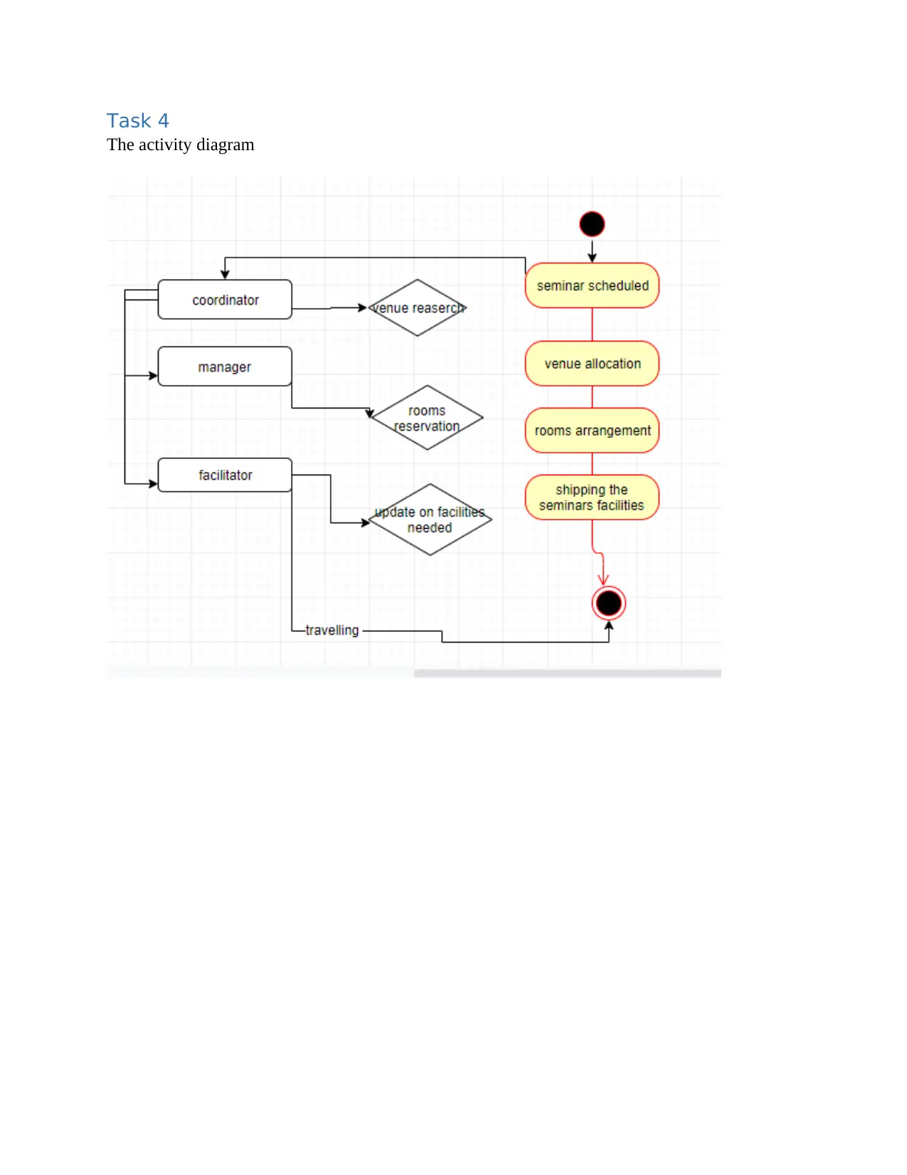
Task 4
The activity diagram
The activity diagram
Paraphrase This Document
Need a fresh take? Get an instant paraphrase of this document with our AI Paraphraser
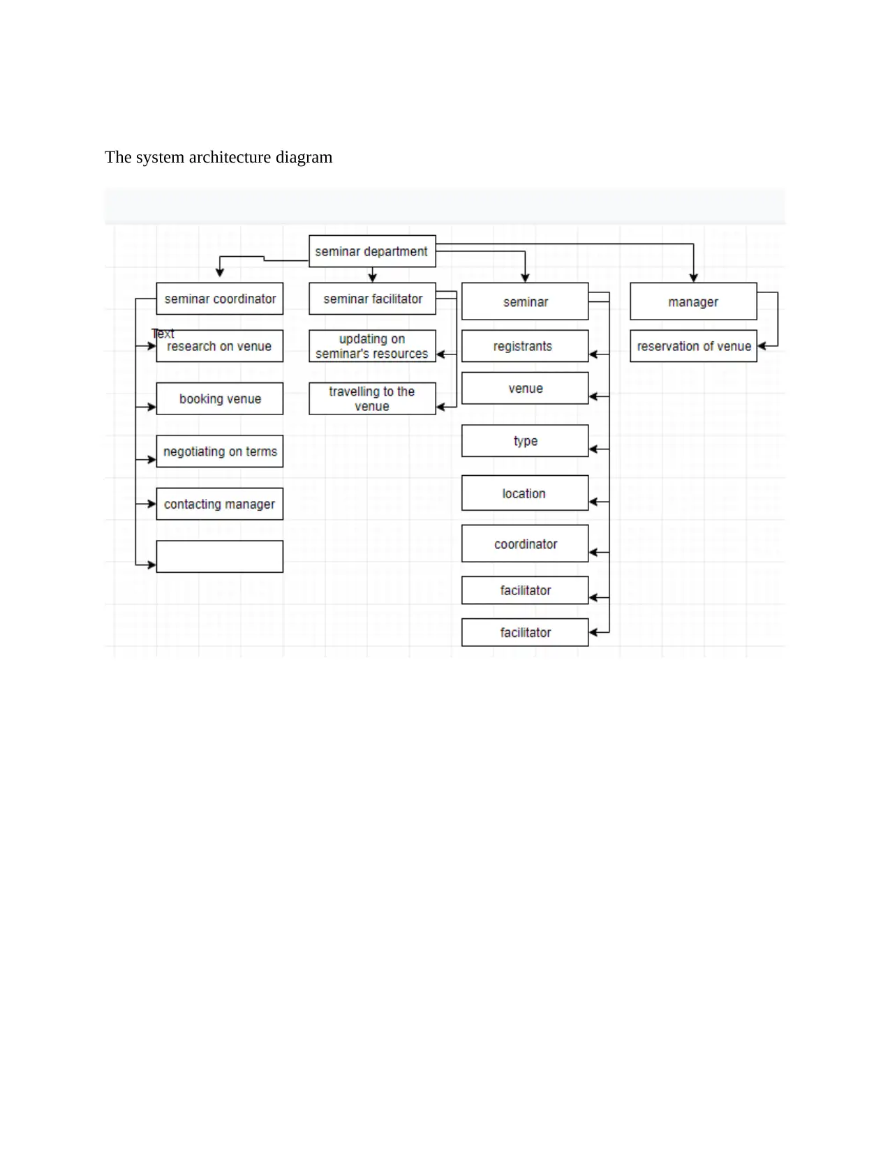
The system architecture diagram
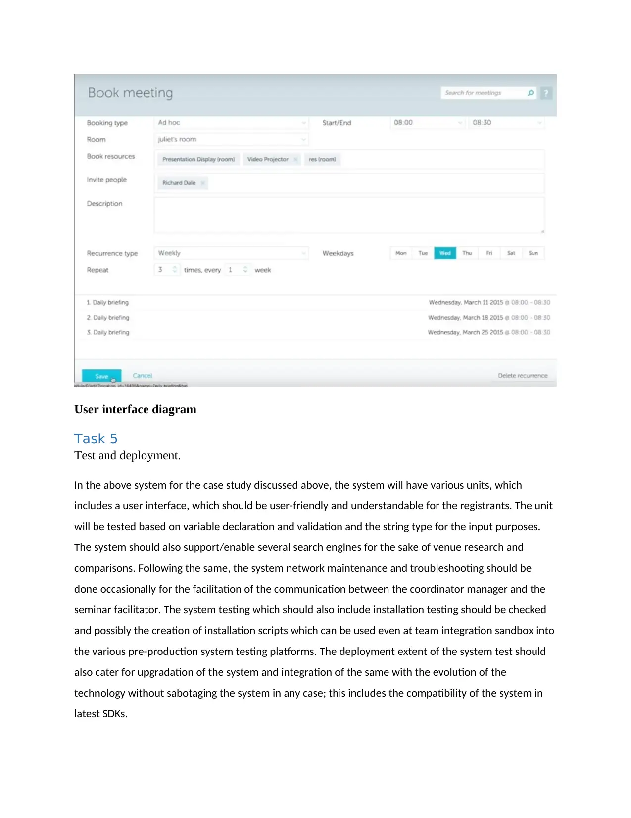
User interface diagram
Task 5
Test and deployment.
In the above system for the case study discussed above, the system will have various units, which
includes a user interface, which should be user-friendly and understandable for the registrants. The unit
will be tested based on variable declaration and validation and the string type for the input purposes.
The system should also support/enable several search engines for the sake of venue research and
comparisons. Following the same, the system network maintenance and troubleshooting should be
done occasionally for the facilitation of the communication between the coordinator manager and the
seminar facilitator. The system testing which should also include installation testing should be checked
and possibly the creation of installation scripts which can be used even at team integration sandbox into
the various pre-production system testing platforms. The deployment extent of the system test should
also cater for upgradation of the system and integration of the same with the evolution of the
technology without sabotaging the system in any case; this includes the compatibility of the system in
latest SDKs.
⊘ This is a preview!⊘
Do you want full access?
Subscribe today to unlock all pages.

Trusted by 1+ million students worldwide
1 out of 14
Related Documents
Your All-in-One AI-Powered Toolkit for Academic Success.
+13062052269
info@desklib.com
Available 24*7 on WhatsApp / Email
![[object Object]](/_next/static/media/star-bottom.7253800d.svg)
Unlock your academic potential
Copyright © 2020–2026 A2Z Services. All Rights Reserved. Developed and managed by ZUCOL.


