logo

System Analysis and Design: Use Case Realisation and Sequence Diagram for Record New Tour Use Case | Desklib


Added on  2023-04-23

12 Pages1898 Words427 Views
System Analysis and Design
Name of Student-
Name of University-
Author’s Note-
System Analysis and Design: Use Case Realisation and Sequence Diagram for Record New Tour Use Case | Desklib_1
Part 1. Use Case Realisation for the ‘Record New Tour’ Use Case
Class Diagram
a) Analysis Class Diagram: Class diagram includes a diagram that basically contains the
classes that are involved in the system that is to be designed. Class diagram is a part of UML
(Unified Modelling language) that defines structure of a particular system that is to be designed.
Class diagram provides the reader and the developer an easy way of designing the software that
defines structure, classes, methods as well as operations of the class that the system will perform.
Class diagram also shows the relationship between the classes that are defined in the diagram.
Class diagram is also known as the conceptual diagram.
System Analysis and Design: Use Case Realisation and Sequence Diagram for Record New Tour Use Case | Desklib_2
b) Class Diagram
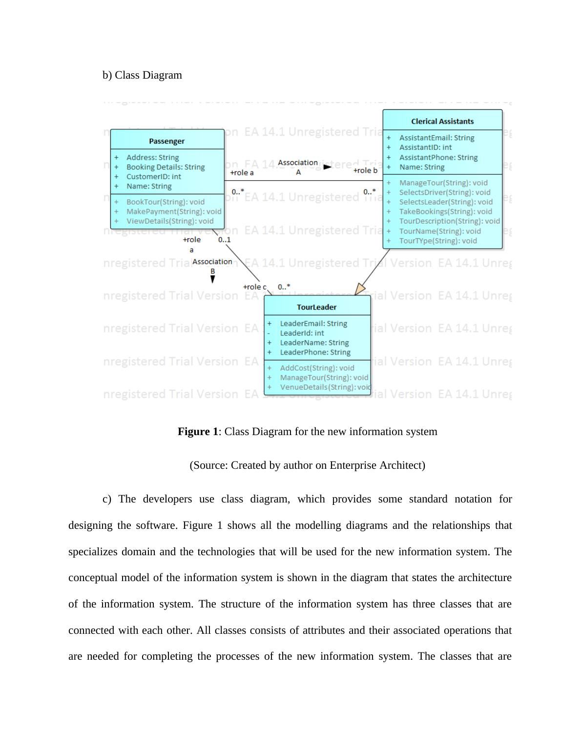
Figure 1: Class Diagram for the new information system
(Source: Created by author on Enterprise Architect)
c) The developers use class diagram, which provides some standard notation for
designing the software. Figure 1 shows all the modelling diagrams and the relationships that
specializes domain and the technologies that will be used for the new information system. The
conceptual model of the information system is shown in the diagram that states the architecture
of the information system. The structure of the information system has three classes that are
connected with each other. All classes consists of attributes and their associated operations that
are needed for completing the processes of the new information system. The classes that are
System Analysis and Design: Use Case Realisation and Sequence Diagram for Record New Tour Use Case | Desklib_3
associated with each other consists of tour leader, passenger, and the clerical assistants. All the
classes have their own operations and the attributes that are needed to carry out a process in the
system.
Communication Diagram
a) Communication Diagram: This is commonly known as collaboration diagram. It is
often known as interaction diagram that shows the relationship as well as the interaction that is in
software objects in the UML languages. These diagrams states the communication in between
the objects that are associated with the new information system. The developers use
communication diagram to make the communication process clear to other developers and the
reader as well. All modelling paradigms that are involved in the system design are stated in the
communication diagram. The communication diagram shows lifelines that are connected with
each other and helps to define the architecture of the system. The message passing is also shown
in the communication diagram.
System Analysis and Design: Use Case Realisation and Sequence Diagram for Record New Tour Use Case | Desklib_4

End of preview

Want to access all the pages? Upload your documents or become a member.

Related Documents
System Analysis and Design
|12
|2170
|463

System Analysis and Design for Record New Tour Use Case
|12
|2418
|416

Enterprise Architect Designing
|13
|2260
|26

System Analysis and Design
|12
|2277
|201

The main purpose of CD in system
|13
|1691
|29

UML Diagrams in Enterprise Architect | Assignment
|12
|2025
|19