System Analysis and Design

Verified

Added on  2023/04/21

|11
|2294
|273
AI Summary
This document provides an overview of system analysis and design, focusing on use case realisation, analysis class diagram, communication diagram, sequence diagram, and evaluation. It discusses the benefits of UML diagrams and the use of the Enterprise Architect case tool. The content includes examples and explanations to help readers understand the concepts and applications of system analysis and design.

Contribute Materials

Your contribution can guide someone’s learning journey. Share your documents today.
Document Page
Running head: SYSTEM ANALYSIS AND DESIGN
System Analysis and Design
Name of the Student
Name of the University
Author’s note:

Secure Best Marks with AI Grader

Need help grading? Try our AI Grader for instant feedback on your assignments.
Document Page
1SYSTEM ANALYSIS AND DESIGN
Table of Contents
Part 1: Use Case Realisation for the ‘Record New Tour’ Use Case...........................................2
1.1 Analysis Class Diagram:..................................................................................................2
1.2 Communication Diagram:................................................................................................3
Part 2: Sequence Diagram..........................................................................................................4
Part 3: Evaluation.......................................................................................................................6
Bibliography:..............................................................................................................................9
Document Page
2SYSTEM ANALYSIS AND DESIGN
Part 1: Use Case Realisation for the ‘Record New Tour’ Use Case
1.1 Analysis Class Diagram:
The UML class diagram is the graphical representation of the classes and its attributes
and operations. These classes are representation of structural model of the TMS application.
Each of the classes has a constructor that provide details of each objects of classes
(Fernandez-Saez et al. 2015). Each of the classes are associated with others through a
relationship. This relationship can be association, inheritance, aggregation and more.
The biggest advantage of the class diagram is providing the most basic design element
of an application and that is classes and its characteristics (Dennis, Wixom and Tegarden
2015). However, the class diagram cannot capture all the characteristics of a class but it can
provide enough details to get a gripping idea of the structural pattern of an application.
Figure 1: Class Diagram of Proposed System
(Source: Created by Author)
Document Page
3SYSTEM ANALYSIS AND DESIGN
The above class diagram shows that the record ne tournament requirement is
established based on three classes. These three classes are tour, driver and clericalAssistant.
Each of these classes has different operations that can be used for different purposes. The
classes are connected to each other using the association relationship. The attributes are
private so that no other package can access the attributes. To make use of the attributes, the
operations are declared as public. Each object of the class will access the attributes through
the operations. This will increase the security of the application directly. One clerical
assistant can record many tours and each tour can have several rivers. There is a limit to enter
the number of drivers but in this case this is not in the concern.
1.2 Communication Diagram:
The communication diagram can be considered as the extension of the class diagram
that only showcase the real communication among the objects of the classes. The
communication diagram uses objects of the classes rather than the class itself and illustrates
how the messages are transferred among the objects (Marrella et al. 2015). It shows the
message flow in a sequence.
The communication diagram is the most scalable diagram of all the UML. The
designer can easily integrate new objects and messages in the communication diagram (Idani
and Ledru 2015). The most popular project methodology, agile development, is suitable for
communication diagram.

Secure Best Marks with AI Grader

Need help grading? Try our AI Grader for instant feedback on your assignments.
Document Page
4SYSTEM ANALYSIS AND DESIGN
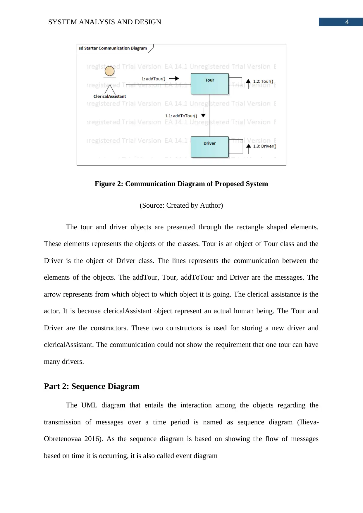
Figure 2: Communication Diagram of Proposed System
(Source: Created by Author)
The tour and driver objects are presented through the rectangle shaped elements.
These elements represents the objects of the classes. Tour is an object of Tour class and the
Driver is the object of Driver class. The lines represents the communication between the
elements of the objects. The addTour, Tour, addToTour and Driver are the messages. The
arrow represents from which object to which object it is going. The clerical assistance is the
actor. It is because clericalAssistant object represent an actual human being. The Tour and
Driver are the constructors. These two constructors is used for storing a new driver and
clericalAssistant. The communication could not show the requirement that one tour can have
many drivers.
Part 2: Sequence Diagram
The UML diagram that entails the interaction among the objects regarding the
transmission of messages over a time period is named as sequence diagram (Ilieva-
Obretenovaa 2016). As the sequence diagram is based on showing the flow of messages
based on time it is occurring, it is also called event diagram
Document Page
5SYSTEM ANALYSIS AND DESIGN
The most important benefit of sequence diagram on system analysis and design is its
simple structure and easy to understand characteristics (Tan et al. 2015). The sequence
diagram is capable of showing the dynamic nature of the application by extending the
outcome of use case diagram.
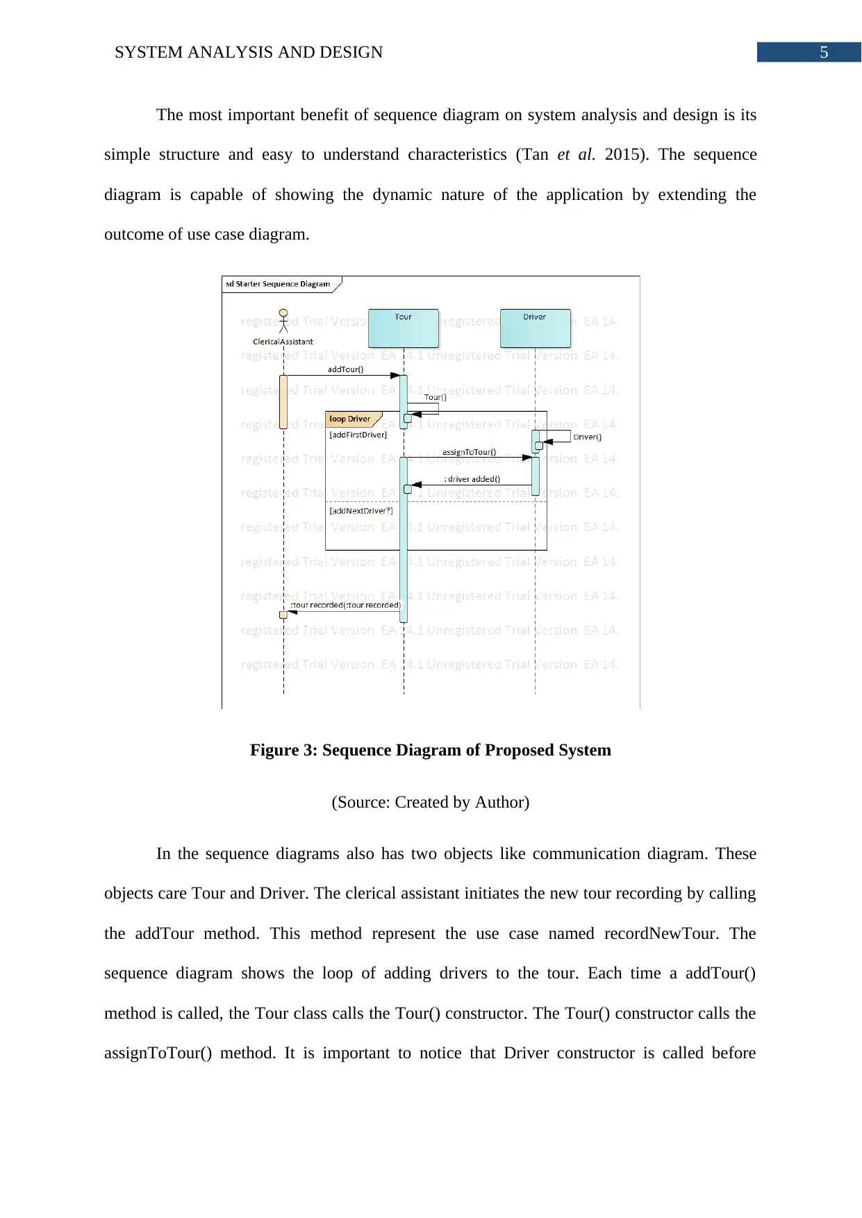
Figure 3: Sequence Diagram of Proposed System
(Source: Created by Author)
In the sequence diagrams also has two objects like communication diagram. These
objects care Tour and Driver. The clerical assistant initiates the new tour recording by calling
the addTour method. This method represent the use case named recordNewTour. The
sequence diagram shows the loop of adding drivers to the tour. Each time a addTour()
method is called, the Tour class calls the Tour() constructor. The Tour() constructor calls the
assignToTour() method. It is important to notice that Driver constructor is called before
Document Page
6SYSTEM ANALYSIS AND DESIGN
assignToTour() method. This means that driver must exists before he/she is assigned to a
tour.
Part 3: Evaluation
The Case Tool selected for this assignment is enterprise architect. The enterprise
architect supports full life cycle models for the software engineering, embedded and real-time
system development and information technology system (Van Den Berg and Van Vliet
2016). The enterprise architect comes with in-built requirement handling features that allows
analysis and design of high level requirements of TMS. The enterprise architect supports
multi-user so that team members can simultaneously work on the designing tasks. The
performance of enterprise architect is extremely high and it can process the requests in
minimal time. The case tool can easily accommodate huge teams which shares the same view
of the business. The enterprise architect provide full traceability regarding the system
requirements, requirement analysis and designs. The designing of the diagrams were very
easy. The case tool provides complete support while creating the designs based on the
analysis done on the enterprise. The impact of the case tool in the analysis is immediate
(Marosin, Van Zee and Ghanavati 2016). Each of the requirement can be validated and
verified using the case tool. The class, communication and sequence diagrams are created
with right information therefore all those designs illustrates accurate representation of the
application. Changing the diagrams are also very easy. The enterprise architect stores the
structure of the diagram element in a separate section even if it is deleted from the graphical
diagram.
The main focus on the Case Tool Enterprise Architecture is all about having an
understanding with respect to design and development of system for understanding its
traceability (Torre et al. 2018). Case Tool does not only support offering which is fully

Paraphrase This Document

Need a fresh take? Get an instant paraphrase of this document with our AI Paraphraser
Document Page
7SYSTEM ANALYSIS AND DESIGN
traceable from the design. In addition, it tends to provide traces for its overall requirements
and analysis. The main idea is all about design where the traceability is considered to be
understandable from the view point of the given task. The fact is not tested that that whether
the features tend to remain for the present diagrams. The current enterprise comes up with
proper kind of features which is required for making changes in the present information
(Gogolla et al. 2017). Enterprise architecture comes up comes up with large number of
information which is required for proper understanding and its analysis of the given needs.
All the required features emphasize on delivery of given task in much better way.
There are certain number tools used by system analysts like case tool which is
required for finishing the current spotlight of the given design for the given application. It is
considered to be very much like codes. There are some kind of engineering tool which helps
in having some simple kind of procedure which will be included in ‘New tour’ for the given
case (Osman and Chaudron 2018). Analysts mainly focus on providing structure for the UML
diagram rather than agonizing the given case tool. It comes up with certain number of
originators which comes up with more number of opportunity for breaking down the present
structure. The diagram is mainly required for finding the present venture design. EA is one of
the simple tool which helps in establishing connection for the given career module. The
present case study can easily give simple interference for proper segment design in the given
groups. It is considered as one of the major diagram which is required for UML based
diagram (Setyautami et al. 2016). Each of the given diagram can be precise in nature and
dynamic parts of the framework which is easily understandable. It tends to provide most
appropriate situation which is required for catching and planning. There are bits of planning
which are required for understanding the present business procedure which is used for
recording the use case of new tour.
Document Page
8SYSTEM ANALYSIS AND DESIGN
The biggest benefit of UML diagram is all about providing support to system analyst
and designer. It is mainly required for capturing both kind of data that is static and dynamic
of the given system (Torre et al. 2018). The overall static structure of the given system is
totally based on basic needs along with whole application. The whole dynamic behavior of
the application highlights the fact that how the static structure can be processed for making
changes in the internal state and making the whole system run (Gogolla et al. 2017). Like a
system analyst or even designer, it is vital for having an understanding the static structure of
the system. UML comes up with fourteen kind of diagram which is needed for capturing the
required aspect of any application.
Document Page
9SYSTEM ANALYSIS AND DESIGN
Bibliography:
Dennis, A., Wixom, B.H. and Tegarden, D., 2015. Systems analysis and design: An object-
oriented approach with UML. John wiley & sons.
Fernandez-Saez, A.M., Genero, M., Chaudron, M.R., Caivano, D. and Ramos, I., 2015. Are
Forward Designed or Reverse-Engineered UML diagrams more helpful for code
maintenance?: A family of experiments. Information and Software Technology, 57, pp.644-
663.
Gogolla, M., Hilken, F., Niemann, P. and Wille, R., 2017, July. Formulating model
verification tasks prover-independently as UML diagrams. In European Conference on
Modelling Foundations and Applications (pp. 232-247). Springer, Cham.
Idani, A. and Ledru, Y., 2015. B for modeling secure information systems. In International
Conference on Formal Engineering Methods (pp. 312-318). Springer, Cham.
Ilieva-Obretenovaa, M., 2016. Information System Functions for SmartGrid
Management. Sociology, 6(2), pp.96-103.
Marosin, D., Van Zee, M. and Ghanavati, S., 2016. Formalizing and modeling enterprise
architecture (EA) principles with goal-oriented requirements language (GRL).
In International Conference on Advanced Information Systems Engineering (pp. 205-220).
Springer, Cham.
Marrella, A., Mecella, M., Russo, A., Steinau, S., Andrews, K. and Reichert, M., 2015. Data
in Business Process Models, A Preliminary Empirical Study (Short Paper). In Service-
Oriented Computing and Applications (SOCA), 2015 IEEE 8th International Conference
on (pp. 116-122). IEEE.

Secure Best Marks with AI Grader

Need help grading? Try our AI Grader for instant feedback on your assignments.
Document Page
10SYSTEM ANALYSIS AND DESIGN
Osman, H. and Chaudron, M.R., 2018. Correctness and Completeness of CASE Tools in
Reverse EngineeringSource Code into UML Model. GSTF Journal on Computing
(JoC), 2(1).
Setyautami, M.R., Hähnle, R., Muschevici, R. and Azurat, A., 2016, September. A UML
profile for delta-oriented programming to support software product line engineering.
In Proceedings of the 20th International Systems and Software Product Line Conference (pp.
45-49). ACM.
Tan, Y., Dong, L., Cao, Y., Yang, L. and Cao, H., 2015. System Analysis of a Hospital
Information System Using UML.
Torre, D., Labiche, Y., Genero, M., Baldassarre, M.T. and Elaasar, M., 2018. UML diagram
synthesis techniques: a systematic mapping study. In 2018 IEEE/ACM 10th International
Workshop on Modelling in Software Engineering (MiSE) (pp. 33-40). IEEE.
Van Den Berg, M. and Van Vliet, H., 2016. The Decision-Making Context Influences the
Role of the Enterprise Architect. In Enterprise Distributed Object Computing Workshop
(EDOCW), 2016 IEEE 20th International (pp. 1-8). IEEE.
1 out of 11
circle_padding
hide_on_mobile
zoom_out_icon
[object Object]

Your All-in-One AI-Powered Toolkit for Academic Success.

Available 24*7 on WhatsApp / Email

[object Object]