IMAT5205: System Analysis and Design Report - Wide World Tour
VerifiedAdded on 2023/04/23
|11
|2205
|266
Report
AI Summary
This report details the system analysis and design of a 'Record New Tour' use case for the Wide World Tour Management System. It begins with an analysis class diagram illustrating the structural model, highlighting the Clerical, Tour, and Driver classes and their associations. A communication diagram is then presented to show the interactions between objects, emphasizing message flows and lifelines. The report further elaborates on a sequence diagram, showcasing the dynamic behavior of the system, including the insertion of tours and assignment of drivers. An evaluation of the Enterprise Architect case tool is included, discussing its features, ease of use, and collaborative capabilities. The author highlights how the tool facilitated the creation of accurate UML diagrams, contributing to a clear representation of the system's requirements and logic, and its advantages in terms of efficient modeling and documentation. The report also underlines the importance of UML diagrams in capturing both static and dynamic patterns of the system, facilitating effective communication between system analysts, designers, and developers.

Running head: SYSTEM ANALYSIS AND DESIGN
System Analysis and Design
Name of the Student
Name of the University
Author’s note:
System Analysis and Design
Name of the Student
Name of the University
Author’s note:
Paraphrase This Document
Need a fresh take? Get an instant paraphrase of this document with our AI Paraphraser
1SYSTEM ANALYSIS AND DESIGN
Table of Contents
Part 1: Use Case Realisation for the ‘Record New Tour’ Use Case...........................................2
1.1 Analysis Class Diagram:..................................................................................................2
1.2 Communication Diagram:................................................................................................3
Part 2: Sequence Diagram..........................................................................................................4
Part 3: Evaluation.......................................................................................................................6
Bibliography:..............................................................................................................................9
2SYSTEM ANALYSIS AND DESIGN
Part 1: Use Case Realisation for the ‘Record New Tour’ Use Case
1.1 Analysis Class Diagram:
The class diagram is the static structural model of unified modelling language. The
class diagram can be described as the collection of basic elements of an application. The
classes illustrates the data and functional requirements of every unit of the application. The
relationship in a class diagram shows the internal communication of application.
The class diagram provides the basic building blocks for the object oriented methods
and it can be considered the most beneficial feature of class diagram. The best way to capture
the structural pattern of an object oriented application is through the class diagram.
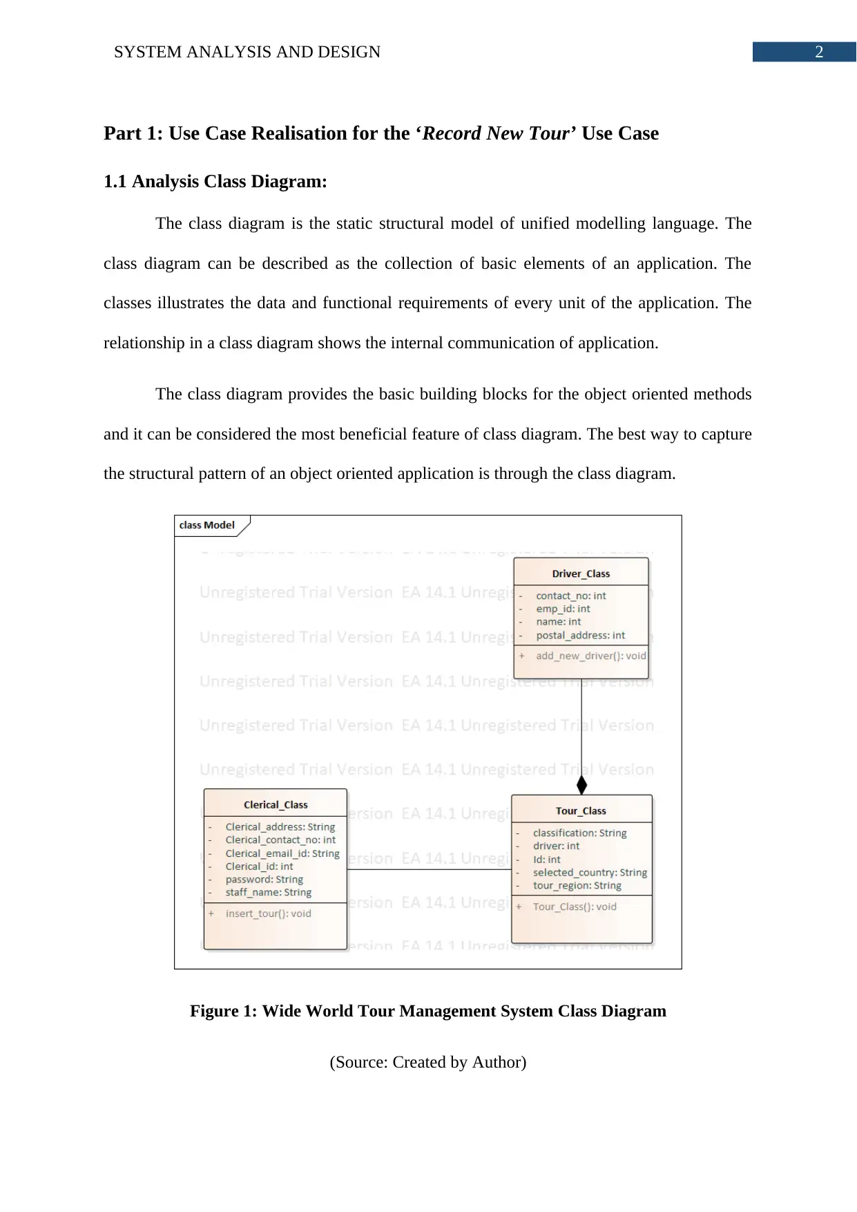
Figure 1: Wide World Tour Management System Class Diagram
(Source: Created by Author)
⊘ This is a preview!⊘
Do you want full access?
Subscribe today to unlock all pages.

Trusted by 1+ million students worldwide
3SYSTEM ANALYSIS AND DESIGN
The class diagram in figure 1 has three classes. As per the description provided in the
record new tour use case, three classes are enough to meet the application requirement. The
class diagram shows that the clerical_class and tour_class are connected through an
association relationship. It is not mentioned in the class diagram how the clerical assistant
methods will be validated or how the assistant can access the system. The class diagram only
concentrated on representing the structural pattern of record new tour use case. Based on the
attributes and operations declared in the figure 1, other unified modelling language diagrams
will be created. The tour class is consisted of only the driver. Therefore, the driver_class and
tour_class has composition relationship among them.
1.2 Communication Diagram:
Communication diagram is also known as the collaboration diagram that shows the
interaction among the objects of the class. The connection between the objects are called the
lifelines. Communication diagram is similar to the sequence diagram and it is a part of
interaction diagram. Communication diagram does not show the structuring mechanism of
the application and life-line of the messages.
Like every other behavioural UML model, the communication diagram shows how
the system will response to requests of users. The communication diagram fills the gap of
class diagram by showing the order of the messages.
Paraphrase This Document
Need a fresh take? Get an instant paraphrase of this document with our AI Paraphraser
4SYSTEM ANALYSIS AND DESIGN
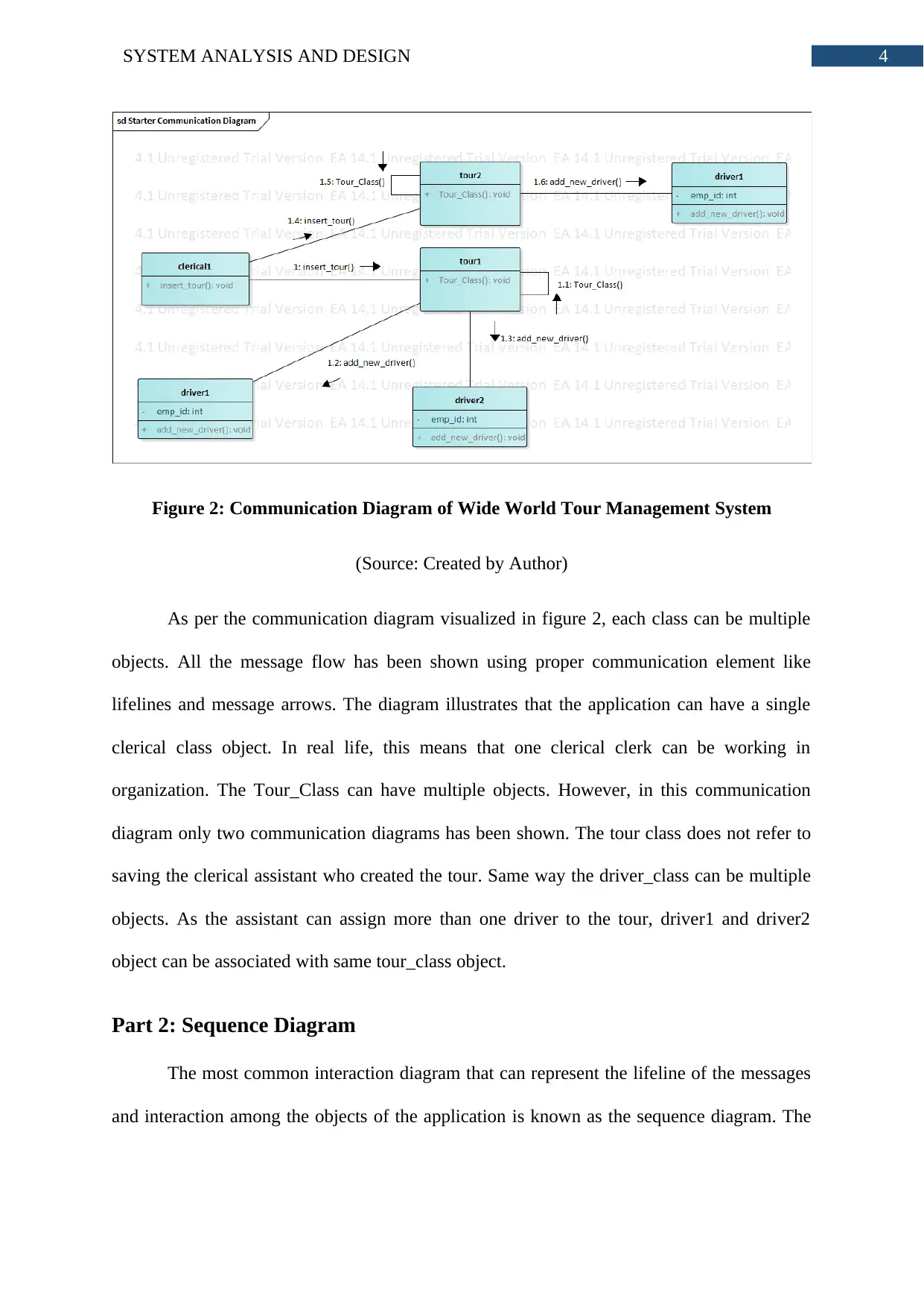
Figure 2: Communication Diagram of Wide World Tour Management System
(Source: Created by Author)
As per the communication diagram visualized in figure 2, each class can be multiple
objects. All the message flow has been shown using proper communication element like
lifelines and message arrows. The diagram illustrates that the application can have a single
clerical class object. In real life, this means that one clerical clerk can be working in
organization. The Tour_Class can have multiple objects. However, in this communication
diagram only two communication diagrams has been shown. The tour class does not refer to
saving the clerical assistant who created the tour. Same way the driver_class can be multiple
objects. As the assistant can assign more than one driver to the tour, driver1 and driver2
object can be associated with same tour_class object.
Part 2: Sequence Diagram
The most common interaction diagram that can represent the lifeline of the messages
and interaction among the objects of the application is known as the sequence diagram. The
5SYSTEM ANALYSIS AND DESIGN
sequence diagram concentrates on interchange of messages among the lifelines. The sequence
diagram also visualizes the sequence of the messages occurring in the application.
In order to capture the dynamic nature of the application or a part of the application,
the sequence diagram has the biggest part among all the other UML diagrams. The class
diagram and communication diagram is not able to show various conditions that are induced
in the login. The sequence diagram can easily represent this conditions through loop and
other if else boxes.
Figure 3: Sequence Diagram of Wide World Tour Management System
(Source: Created by Author)
⊘ This is a preview!⊘
Do you want full access?
Subscribe today to unlock all pages.

Trusted by 1+ million students worldwide
6SYSTEM ANALYSIS AND DESIGN
Each of the objects is a reference to the classes, showed in the figure 1. The first
message called in the record new tour application is the insert_tour(). The sequence diagram
shows that the insert_tour() message will be called two times as two tours will be created.
The messages are called after the first insert_tour() message lifeline is complete. This
illustrates that two insert_tour() messages will function independently. The sequence
diagram, however, does not show the limit if tour and assigning drivers to tour. Now the
constructor Tour_Class() will be called by the tour1 and tour2 objects to assign values to the
attributes. The add_new_driver() method is called through this constructor to assign a driver
to the tour. The figure 3 shows that two drivers will be added to tour1 and one driver will be
added to tour2.
Part 3: Evaluation
Sparx System developed the Enterprise Architect Case Tool for allowing the system
analysts and designers to conduct their work efficiently, accurately and effectively. The
Computer Aided Software Engineering tools is considered to be the set of applications that
can handle computer assisted tools and procedures in terms of development of software. The
applications work collaboratively for creating error free diagrams and high quality designs for
software. The enterprise architect case tool support not only the information and
communication technology systems but also the embedded implementation. Every process is
done through verifying the check-points and every activity is gone through specific
disciplines so that whole process of analysis and design can be done as per project
deliverable. This feature of enterprise architect allows the system analysts and designer to
process their work as per the milestone, developed during the project planning. Loading the
files were very fast and it allowed to concentrate more on the work rather than waiting for the
modules to be loaded. The enterprise architect case tool allows creating robust and accurate
diagrams through its in-built feature called right information flow. Each information entered
Paraphrase This Document
Need a fresh take? Get an instant paraphrase of this document with our AI Paraphraser
7SYSTEM ANALYSIS AND DESIGN
in the diagram are valeted and always have right details. Each of the diagrams are maintained
properly, automatically by the case tool. The biggest impact of enterprise architect is
collaboration. The case tool allows project teams members to collaborate and run the work on
same files no matter where they are.
As a system analyst and designer, the first work was to collect the requirement of the
system by analysing the use case description. The task was to generate diagrams that can
satisfy the needs of the record new tour use case. The enterprise architect was equipped with
a very friendly user interface that allowed to understand its features and how to use enterprise
architect. The diagrams were easy to create because of the drag and drop feature of enterprise
architect. To create the classes, the classes are dragged into the editing area. Adding the
attributes and operations were very efficient because enterprise architect provide a window in
which the attribute and operations can be added and the list can be maintained. The access
identifier and data types can be selected from the list. Therefore, the chance of imputing
wrong information is extremely low. This makes the analyst and design responsibilities
lighter as the enterprise architect can handle a few things automatically. The case tool also
stores the diagrams as documentation. The documentation feature allowed to see the deleted
elements in the diagram so that later it can be edited or added back to diagram. Creating the
class diagram was the first task that had been done. The enterprise architect tool allowed to
enter the elements of classes, edit the classes and add relationships very efficiently. All the
attributes were assigned with accurate data types.
The UML or unified modelling language is primarily used by the system analysts and
designers for visually representing the entities of the system. The UML diagrams has a part
called class diagram that allows the designers to capture the static structure of the
applications. The class diagram also shows the relationship among the classes that allows the
analysts to represent how the classes will communicate with each other during run time. No

8SYSTEM ANALYSIS AND DESIGN
matter who has developed the diagrams, any system analyst or designer can get an idea of
what is meant to be represented through the UML diagrams. It is because, the UML diagrams
are very easy to understand. The diagrams are also easy to create. This allows the designer to
convert the requirements of the system to visual diagrams very easily. The job of the system
analyst and designer is to provide accurate system related logic and information to the
developers. The system designer also validate their system requirements while creating the
diagrams. Therefore, the UML diagrams allows the designers to create an accurate login for
the application. Each UML diagram is consisted of relationships. These relationships allows
the designers to capture and represent the internal communication of the system entities. As
the UML diagram is the present standard for object oriented programming, the availability of
information is much more than other modelling language. This way the designers can easily
know the things essential for creating a complex model. The UML modelling language
supports a lot of diagrams that allows capturing both the dynamic and static patterns of the
system.
⊘ This is a preview!⊘
Do you want full access?
Subscribe today to unlock all pages.

Trusted by 1+ million students worldwide

9SYSTEM ANALYSIS AND DESIGN
Bibliography:
Bashir, R.S., Lee, S.P., Khan, S.U.R., Chang, V. and Farid, S., 2016. UML models
consistency management: Guidelines for software quality manager. International Journal of
Information Management, 36(6), pp.883-899.
Bhutto, A. and Hussain, D.M.A., 2018. Validate UML Model and OCL Expressions Using
USE Tool. Pertanika Journal of Science and Technology (jst), 26(3), pp.1465-1480.
Burgueno, L., Gogolla, M. and Vallecillo, A., 2017. Teaching model views with UML and
OCL.
Burgueno, L., Vallecillo, A. and Gogolla, M., 2018. Teaching UML and OCL models and
their validation to software engineering students: an experience report. Computer Science
Education, pp.1-19.
El Ahmar, Y., Le Pallec, X. and Gerard, S., 2016. Empirical Activity: Assessing the
Perceptual Properties of the Size Visual Variation in UML Sequence Diagram. In HuFaMo
workshop.
Fernandez-Saez, A.M., Genero, M., Chaudron, M.R., Caivano, D. and Ramos, I., 2015. Are
Forward Designed or Reverse-Engineered UML diagrams more helpful for code
maintenance?: A family of experiments. Information and Software Technology, 57, pp.644-
663.
Tan, Y., Dong, L., Cao, Y., Yang, L. and Cao, H., 2015. System Analysis of a Hospital
Information System Using UML.
Torre, D., Labiche, Y., Genero, M., Baldassarre, M.T. and Elaasar, M., 2018. UML diagram
synthesis techniques: a systematic mapping study. In 2018 IEEE/ACM 10th International
Workshop on Modelling in Software Engineering (MiSE) (pp. 33-40). IEEE.
Paraphrase This Document
Need a fresh take? Get an instant paraphrase of this document with our AI Paraphraser

10SYSTEM ANALYSIS AND DESIGN
Van Den Berg, M. and Van Vliet, H., 2016. The Decision-Making Context Influences the
Role of the Enterprise Architect. In Enterprise Distributed Object Computing Workshop
(EDOCW), 2016 IEEE 20th International (pp. 1-8). IEEE.
Vargas, A., Cuenca, L., Boza, A., Sacala, I. and Moisescu, M., 2016. Towards the
development of the framework for inter sensing enterprise architecture. Journal of Intelligent
Manufacturing, 27(1), pp.55-72.
Vatankhah Barenji, R., Hashemipour, M. and Guerra-Zubiaga, D.A., 2015. A framework for
modelling enterprise competencies: from theory to practice in enterprise
architecture. International Journal of Computer Integrated Manufacturing, 28(8), pp.791-
810.
1 out of 11
Related Documents
Your All-in-One AI-Powered Toolkit for Academic Success.
+13062052269
info@desklib.com
Available 24*7 on WhatsApp / Email
![[object Object]](/_next/static/media/star-bottom.7253800d.svg)
Unlock your academic potential
Copyright © 2020–2025 A2Z Services. All Rights Reserved. Developed and managed by ZUCOL.


