System Analysis and Design
VerifiedAdded on 2023/04/22
|11
|2293
|223
AI Summary
This document discusses the use case realisation for the 'Record New Tour' use case, including analysis class diagram, communication diagram, and sequence diagram. It also evaluates the use of Enterprise Architect case tool in the system analysis and design process.
Contribute Materials
Your contribution can guide someone’s learning journey. Share your
documents today.

Running head: SYSTEM ANALYSIS AND DESIGN
System Analysis and Design
Name of the Student
Name of the University
Author’s note:
System Analysis and Design
Name of the Student
Name of the University
Author’s note:
Secure Best Marks with AI Grader
Need help grading? Try our AI Grader for instant feedback on your assignments.
1SYSTEM ANALYSIS AND DESIGN
Table of Contents
Part 1: Use Case Realisation for the ‘Record New Tour’ Use Case...........................................2
1.1 Analysis Class Diagram:..................................................................................................2
1.2 Communication Diagram:................................................................................................3
Part 2: Sequence Diagram..........................................................................................................4
Part 3: Evaluation.......................................................................................................................6
Bibliography:..............................................................................................................................9
2SYSTEM ANALYSIS AND DESIGN
Part 1: Use Case Realisation for the ‘Record New Tour’ Use Case
1.1 Analysis Class Diagram:
The classes are the blueprint of the objects. It defines the functionality and the
purpose of the object. In order to get a static view of the application, the class diagrams are
created. The purpose of the class diagram is to describe the types of objects exists in the
application along with relationships those objects have. Almost all the object oriented
methods are suitable for class diagrams.
The complex data model of the information systems can be easily illustrated through
the class diagram. The structure of the application can also be understood easily.
Figure 1: Class Diagram of Proposed System
(Source: Created by Author)
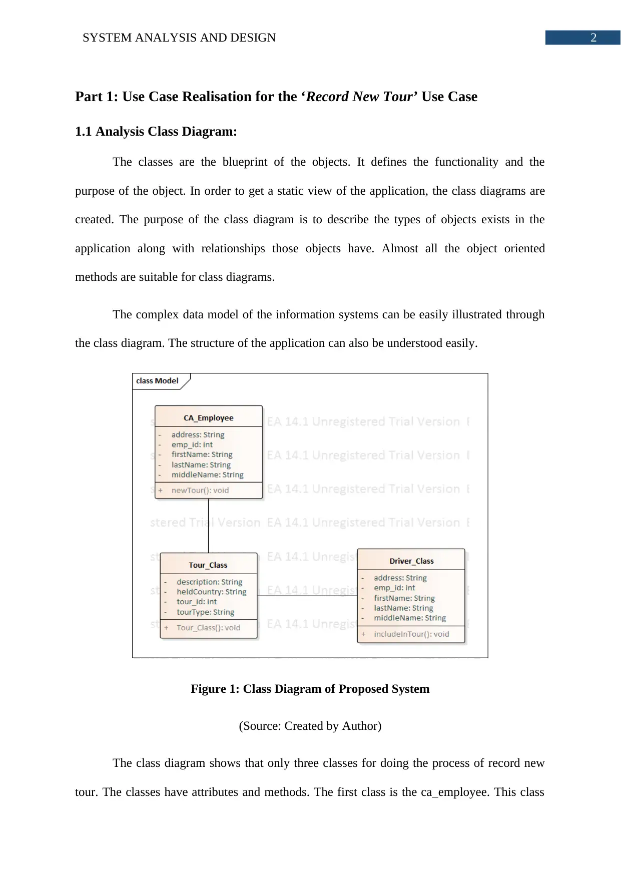
The class diagram shows that only three classes for doing the process of record new
tour. The classes have attributes and methods. The first class is the ca_employee. This class
Part 1: Use Case Realisation for the ‘Record New Tour’ Use Case
1.1 Analysis Class Diagram:
The classes are the blueprint of the objects. It defines the functionality and the
purpose of the object. In order to get a static view of the application, the class diagrams are
created. The purpose of the class diagram is to describe the types of objects exists in the
application along with relationships those objects have. Almost all the object oriented
methods are suitable for class diagrams.
The complex data model of the information systems can be easily illustrated through
the class diagram. The structure of the application can also be understood easily.
Figure 1: Class Diagram of Proposed System
(Source: Created by Author)
The class diagram shows that only three classes for doing the process of record new
tour. The classes have attributes and methods. The first class is the ca_employee. This class
3SYSTEM ANALYSIS AND DESIGN
stores the data model of clerical assistant. On the other hand, the tour_class and Driver_class
represent the data model of tour and driver respectively. Each class has a method. These
methods are marked as public so that other classes can access the data of other class through
this methods. The classes has association relationship among them. The structural pattern of
the record new tour use case is very simple that is why no composition or inheritance like
complex relationships has not been used. The newTour() method is declared in the
ca_employee class, Tour_class() is the constructor of the Tour_class class and the
includeInTour() method is declared in Drver_class class.
1.2 Communication Diagram:
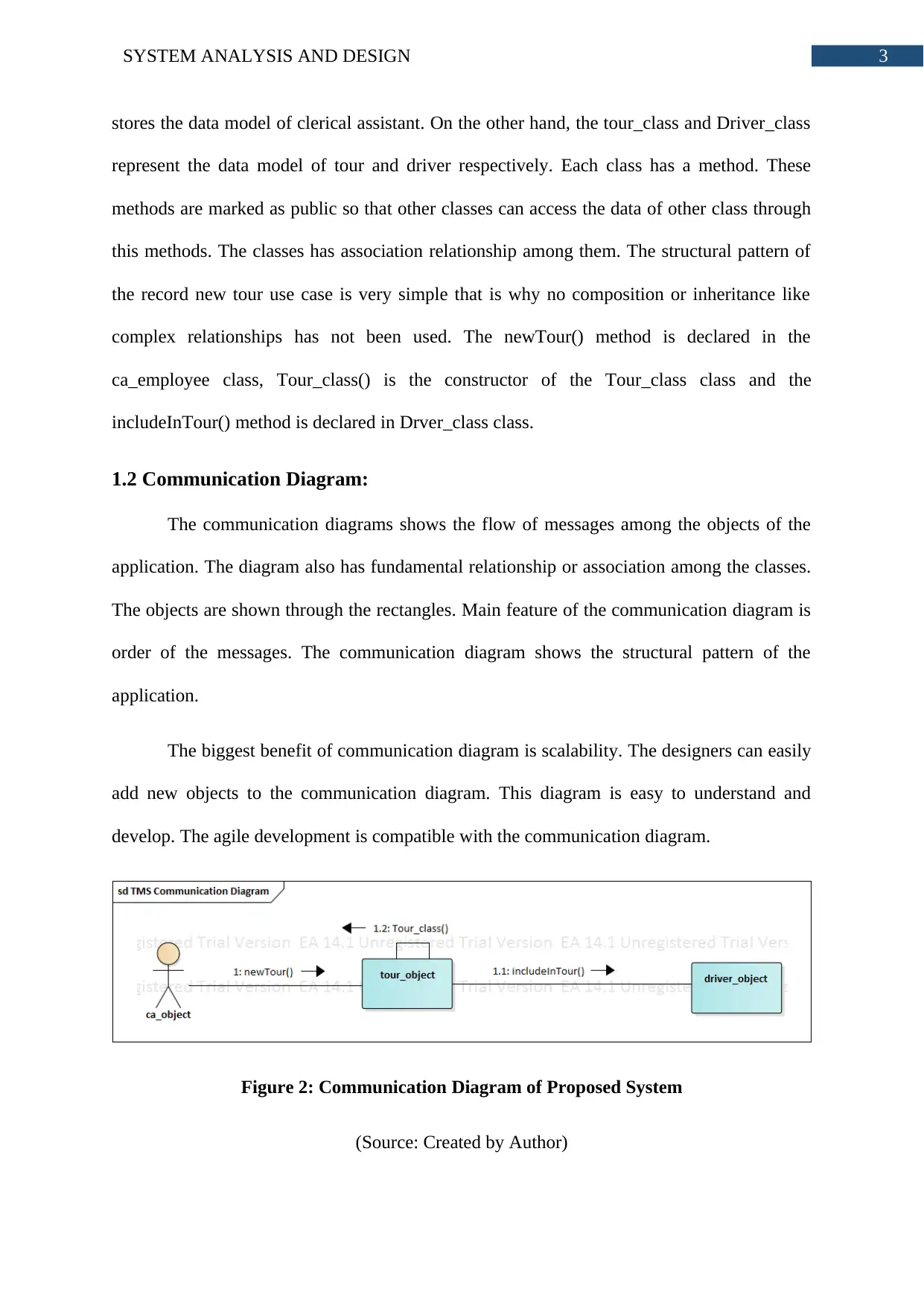
The communication diagrams shows the flow of messages among the objects of the
application. The diagram also has fundamental relationship or association among the classes.
The objects are shown through the rectangles. Main feature of the communication diagram is
order of the messages. The communication diagram shows the structural pattern of the
application.
The biggest benefit of communication diagram is scalability. The designers can easily
add new objects to the communication diagram. This diagram is easy to understand and
develop. The agile development is compatible with the communication diagram.
Figure 2: Communication Diagram of Proposed System
(Source: Created by Author)
stores the data model of clerical assistant. On the other hand, the tour_class and Driver_class
represent the data model of tour and driver respectively. Each class has a method. These
methods are marked as public so that other classes can access the data of other class through
this methods. The classes has association relationship among them. The structural pattern of
the record new tour use case is very simple that is why no composition or inheritance like
complex relationships has not been used. The newTour() method is declared in the
ca_employee class, Tour_class() is the constructor of the Tour_class class and the
includeInTour() method is declared in Drver_class class.
1.2 Communication Diagram:
The communication diagrams shows the flow of messages among the objects of the
application. The diagram also has fundamental relationship or association among the classes.
The objects are shown through the rectangles. Main feature of the communication diagram is
order of the messages. The communication diagram shows the structural pattern of the
application.
The biggest benefit of communication diagram is scalability. The designers can easily
add new objects to the communication diagram. This diagram is easy to understand and
develop. The agile development is compatible with the communication diagram.
Figure 2: Communication Diagram of Proposed System
(Source: Created by Author)
Secure Best Marks with AI Grader
Need help grading? Try our AI Grader for instant feedback on your assignments.

4SYSTEM ANALYSIS AND DESIGN
The communication diagram visualized in the figure 2 shows three objects of three
classes. For each class presented in the figure 1, there is one object. For showing the loop,
more than one object of the driver_class cloud be created but the use case shows only one
driver was added to the tour. The communication diagram shows the flow of the messages in
order. The tour_class() constrictor has been represented by showing message flow between
same object. However, the communication diagram does not show the life cycle of the
messages.
Part 2: Sequence Diagram
The UML sequence diagram is the graphical representation of the flow of messages in
an application based on the time sequence it is executed. The sequence diagram is made
through combining the use case diagram and the class diagram. The sequence diagram is
done by capturing the dynamic nature of the application.
The sequence diagram allows documentation and validation of the logic. The
sequence diagram shows the flow of messages in sequence and also the lifetime of the
messages. This allows better understanding of how the application process each user request.
5SYSTEM ANALYSIS AND DESIGN
Figure 3: Sequence Diagram of Proposed System
(Source: Created by Author)
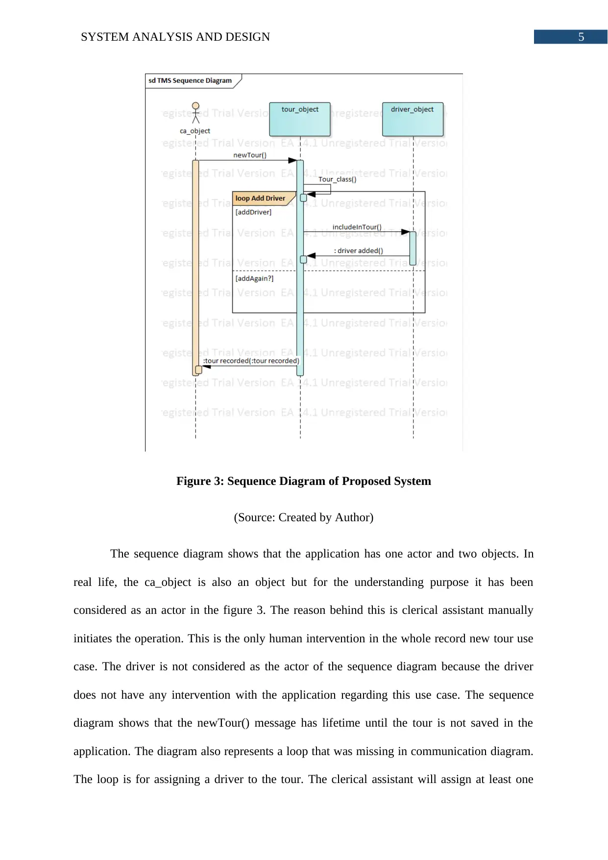
The sequence diagram shows that the application has one actor and two objects. In
real life, the ca_object is also an object but for the understanding purpose it has been
considered as an actor in the figure 3. The reason behind this is clerical assistant manually
initiates the operation. This is the only human intervention in the whole record new tour use
case. The driver is not considered as the actor of the sequence diagram because the driver
does not have any intervention with the application regarding this use case. The sequence
diagram shows that the newTour() message has lifetime until the tour is not saved in the
application. The diagram also represents a loop that was missing in communication diagram.
The loop is for assigning a driver to the tour. The clerical assistant will assign at least one
Figure 3: Sequence Diagram of Proposed System
(Source: Created by Author)
The sequence diagram shows that the application has one actor and two objects. In
real life, the ca_object is also an object but for the understanding purpose it has been
considered as an actor in the figure 3. The reason behind this is clerical assistant manually
initiates the operation. This is the only human intervention in the whole record new tour use
case. The driver is not considered as the actor of the sequence diagram because the driver
does not have any intervention with the application regarding this use case. The sequence
diagram shows that the newTour() message has lifetime until the tour is not saved in the
application. The diagram also represents a loop that was missing in communication diagram.
The loop is for assigning a driver to the tour. The clerical assistant will assign at least one
6SYSTEM ANALYSIS AND DESIGN
driver to the tour. The system provides the possibility of adding more than driver to the tour.
For this reason, the loop of add driver has been added.
Part 3: Evaluation
The Case Tool can be considered as the collection of software application for making
the SDLC procedures automatic. In this case the Enterprise Architect case tool has been used.
The Case Tool has provided a great benefit in analysing the World-Wide Tours requirements.
There are various Case Tools available for analyzing and designing the system. However, the
advantages of Enterprise Architect like minimal loading time, accurate documentation,
requirement validation and many more has been a crucial part for selecting the Case Tool.
The class diagram, sequence diagram and communication diagram creation was very easy in
Enterprise Architect. The final diagrams are accurate and illustrates the exact requirement of
the tour management system. Accuracy has been achieved for system components, control
flow and data. Visualization of the structural patterns of the application has been properly
graphically represented. The Enterprise Case tool allows collaboration among the team
members. Because of this analyzing the proposed system and making the diagrams was more
efficient. The Enterprise Architect comes with various features like tractability. The
traceability has been seen for requirements, evaluation and designing. From the planning to
the completion of the design, this traceability feature has played a great part in this
assignment. The record new tour use case illustrated some complex information that needed
to be evaluated. With the in-built characteristics of enterprise architect, the handling of
complex information became very easy and only the right information was flowing from one
stage to another.
During the system analysis and design a good atmosphere along with easy methods of
modification has been provided by Enterprise Architect Case Tool. Capturing the
Paraphrase This Document
Need a fresh take? Get an instant paraphrase of this document with our AI Paraphraser
7SYSTEM ANALYSIS AND DESIGN
requirements at first attempt is not possible (Berzisa, Bravos and Gonzalez 2015). The perfect
diagrams have been created after few attempts in converting various internal aspects of
application in numerous UML diagrams. At first the class diagram has been designed, on the
basis of their findings, sequence diagrams and components were created. Component diagram
depicts sequence of various messages in the application; this helps the designers in aligning
technical requirements along with business requirements.
The basic support provided by case tools to an analyst or designer would be a detailed
focus on architecture which belong to the application that has been proposed, it does not get
concerned regarding the codes. New requirements are allowed into the use case ‘add new
tour’ with the help of easy methods; this is done by the case tools of enterprise architecture.
This method helps the designers to concentrate on designing various UML diagrams instead
of thinking about how case tool works (Vargas, Cuenca and Boza 2016). This was of utmost
importance because the designers require more amount of time for designing and analyzing
the diagrams instead of gaining knowledge regarding enterprise architecture. The EA tool
case consists of a user interaction module which is very easy to utilize along with enabling
the creation of diagrams in an easy way. Case tool provides easy and useful modifications
(Khan, Jan and Tahir 2016). Case tools also provide methods which help in developing
interface for the purpose of creating component diagram as well as sequence diagram. This
helps in supporting the entire set of elements of the UML diagrams. The diagrams have been
created with complete accuracy so that the dynamic as well as structural features of that
particular system are allowed to capture perfectly. A perfect environment has been provided
in order to capture as well as design various insights of the business processes for recording a
new use case tool.
For the purpose of collecting various structural as well as behavioral patterns related
to this proposed system, UML diagrams are extremely important. The basic and important

8SYSTEM ANALYSIS AND DESIGN
elements of the proposed system have been possible due to the developed class diagram.
Every class consists of two parts like operations and attributes. At the time of designing the
class diagram, structural patterns in the application were identified with the help of data sets
that belonged to each class as well as the methods which utilizes these attributes for
processing data. Component diagram is a similar structural diagram which is created in the
assignment. Component diagram had helped in developing knowledge regarding message
transmission among various objects of classes (Vatankhah, Hashemipour and Guerra-Zubiaga
2015). The basic effect of component diagram is, it allows in identifying sequence of various
messages on the basis of the time it has been sent. The pattern of dynamic modeling is being
followed by sequence diagram. The communication among various objects including the
messages as well as replies is shown by sequence diagram. UML diagram accurately depicts
the internal elements of Wide World Tour Management System along with the
communication among them.
9SYSTEM ANALYSIS AND DESIGN
Bibliography:
Berzisa, S., Bravos, G., Gonzalez, T.C., Czubayko, U., España, S., Grabis, J., Henkel, M.,
Jokste, L., Kampars, J., Koç, H. and Kuhr, J.C., 2015. Capability driven development: an
approach to designing digital enterprises. Business & Information Systems
Engineering, 57(1), pp.15-25.
Dennis, A., Wixom, B.H. and Tegarden, D., 2015. Systems analysis and design: An object-
oriented approach with UML. John wiley & sons.
Fernandez-Saez, A.M., Genero, M., Chaudron, M.R., Caivano, D. and Ramos, I., 2015. Are
Forward Designed or Reverse-Engineered UML diagrams more helpful for code
maintenance?: A family of experiments. Information and Software Technology, 57, pp.644-
663.
Khan, F., Jan, S.R., Tahir, M., Khan, S. and Ullah, F., 2016. Survey: Dealing Non-Functional
Requirements at Architecture Level. VFAST Transactions on Software Engineering, 9(2),
pp.7-13.
Osman, H. and Chaudron, M.R., 2018. Correctness and Completeness of CASE Tools in
Reverse EngineeringSource Code into UML Model. GSTF Journal on Computing
(JoC), 2(1).
Setyautami, M.R., Hähnle, R., Muschevici, R. and Azurat, A., 2016, September. A UML
profile for delta-oriented programming to support software product line engineering.
In Proceedings of the 20th International Systems and Software Product Line Conference (pp.
45-49). ACM.
Tan, Y., Dong, L., Cao, Y., Yang, L. and Cao, H., 2015. System Analysis of a Hospital
Information System Using UML.
Secure Best Marks with AI Grader
Need help grading? Try our AI Grader for instant feedback on your assignments.

10SYSTEM ANALYSIS AND DESIGN
Torre, D., Labiche, Y., Genero, M., Baldassarre, M.T. and Elaasar, M., 2018. UML diagram
synthesis techniques: a systematic mapping study. In 2018 IEEE/ACM 10th International
Workshop on Modelling in Software Engineering (MiSE) (pp. 33-40). IEEE.
Van Den Berg, M. and Van Vliet, H., 2016. The Decision-Making Context Influences the
Role of the Enterprise Architect. In Enterprise Distributed Object Computing Workshop
(EDOCW), 2016 IEEE 20th International (pp. 1-8). IEEE.
Vargas, A., Cuenca, L., Boza, A., Sacala, I. and Moisescu, M., 2016. Towards the
development of the framework for inter sensing enterprise architecture. Journal of Intelligent
Manufacturing, 27(1), pp.55-72.
Vatankhah Barenji, R., Hashemipour, M. and Guerra-Zubiaga, D.A., 2015. A framework for
modelling enterprise competencies: from theory to practice in enterprise
architecture. International Journal of Computer Integrated Manufacturing, 28(8), pp.791-
810.
1 out of 11
Related Documents


Your All-in-One AI-Powered Toolkit for Academic Success.
+13062052269
info@desklib.com
Available 24*7 on WhatsApp / Email
![[object Object]](/_next/static/media/star-bottom.7253800d.svg)
Unlock your academic potential
© 2024 | Zucol Services PVT LTD | All rights reserved.