Analysis and Design: Use Case Realisation in Tour Management System
VerifiedAdded on 2023/04/21
|12
|2423
|352
Report
AI Summary
This report provides a detailed analysis and design of a system, focusing on the 'Record New Tour' use case. It includes an analysis class diagram illustrating the static framework of the application with classes, attributes, and operations, as well as a communication diagram showing the interactions between objects. A sequence diagram visualizes the flow of messages between objects over time. The report also evaluates the usefulness of UML diagrams and CASE tools like Enterprise Architect in the analysis and design process, highlighting their benefits for modeling, collaboration, and simulation. The UML diagrams facilitate clear communication among stakeholders and capture both the dynamic and static aspects of the system, aiding in the development of robust and well-documented software architecture. The final evaluation discusses the benefits of using UML diagrams and CASE tools in object-oriented system projects.

Running head: SYSTEM ANALYSIS AND DESIGN
System Analysis and Design
Name of the Student
Name of the University
Author’s note:
System Analysis and Design
Name of the Student
Name of the University
Author’s note:
Paraphrase This Document
Need a fresh take? Get an instant paraphrase of this document with our AI Paraphraser
1SYSTEM ANALYSIS AND DESIGN
Table of Contents
Part 1: Use Case Realisation for the ‘Record New Tour’ Use Case...........................................2
1.1 Analysis Class Diagram:..................................................................................................2
1.2 Communication Diagram:................................................................................................3
Part 2: Sequence Diagram..........................................................................................................4
Part 3: Evaluation.......................................................................................................................6
Bibliography:..............................................................................................................................9
2SYSTEM ANALYSIS AND DESIGN
Part 1: Use Case Realisation for the ‘Record New Tour’ Use Case
1.1 Analysis Class Diagram:
The diagram called class model is a part of the UML diagrams that describes the static
framework of the proposed application. The static structure refers to the classes of the
application and the elements of it. A class is consisted of attributes and operations. In a
diagram called class, the linkamong the classes shows how system will establish internal
communication.
The class model is extremely beneficial for system design because it can offer basic
structure for developing dynamic UML models. The diagram called class model may be also
used as the data model as the attributes can represent what kind of data the classes will hold.
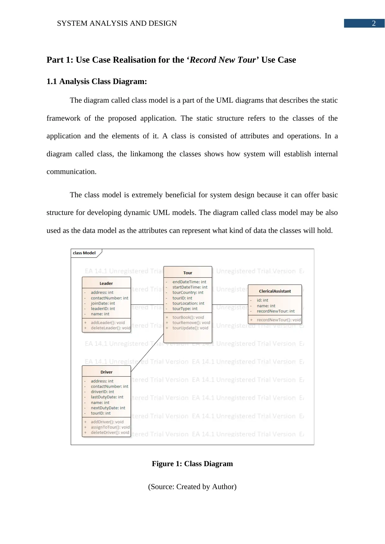
Figure 1: Class Diagram
(Source: Created by Author)
⊘ This is a preview!⊘
Do you want full access?
Subscribe today to unlock all pages.

Trusted by 1+ million students worldwide
3SYSTEM ANALYSIS AND DESIGN
The figure 1 represent the class model of the proposed TMS. The class diagram has
four classes. Each diagram has its attributes and methods. The methods are declared as the
public access modifier. Each method can only access the attributes of its own class. The
Tourclass represents the real life tour’s data models and methods. As per the diagram, the
clerical assistant class calls the record new tour method.
1.2 Communication Diagram:
The unified modelling language has both static and dynamic diagrams and the most
basic dynamic diagram can be considered to be the communication diagram. The
communication diagram is a part of interaction diagram like sequence diagram. The
communication diagram shows how the objects of the application interacts with each other.
The communication diagram consist of the objects that communicates and the messages that
are used for showing the communication.
The biggest advantage of communication diagram is that it can show the order in
which objects will communicate with each other. The messages are drawn with arrows that
also describes which object calls and which object reacts.
Paraphrase This Document
Need a fresh take? Get an instant paraphrase of this document with our AI Paraphraser
4SYSTEM ANALYSIS AND DESIGN
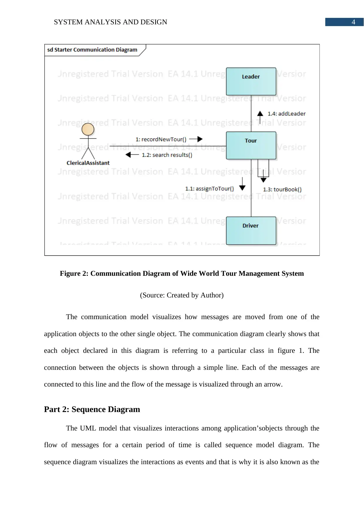
Figure 2: Communication Diagram of Wide World Tour Management System
(Source: Created by Author)
The communication model visualizes how messages are moved from one of the
application objects to the other single object. The communication diagram clearly shows that
each object declared in this diagram is referring to a particular class in figure 1. The
connection between the objects is shown through a simple line. Each of the messages are
connected to this line and the flow of the message is visualized through an arrow.
Part 2: Sequence Diagram
The UML model that visualizes interactions among application’sobjects through the
flow of messages for a certain period of time is called sequence model diagram. The
sequence diagram visualizes the interactions as events and that is why it is also known as the
5SYSTEM ANALYSIS AND DESIGN
event diagrams. The sequence diagram can represent the dynamic nature of the application
and visualize the runtime situations.
The most important benefit of the sequence diagram is that it can provide the
description of the communication based on the order it is called and its lifecycle. The
sequence diagram is the most powerful dynamic model as it accurately captures the contents
of class and use case diagrams.
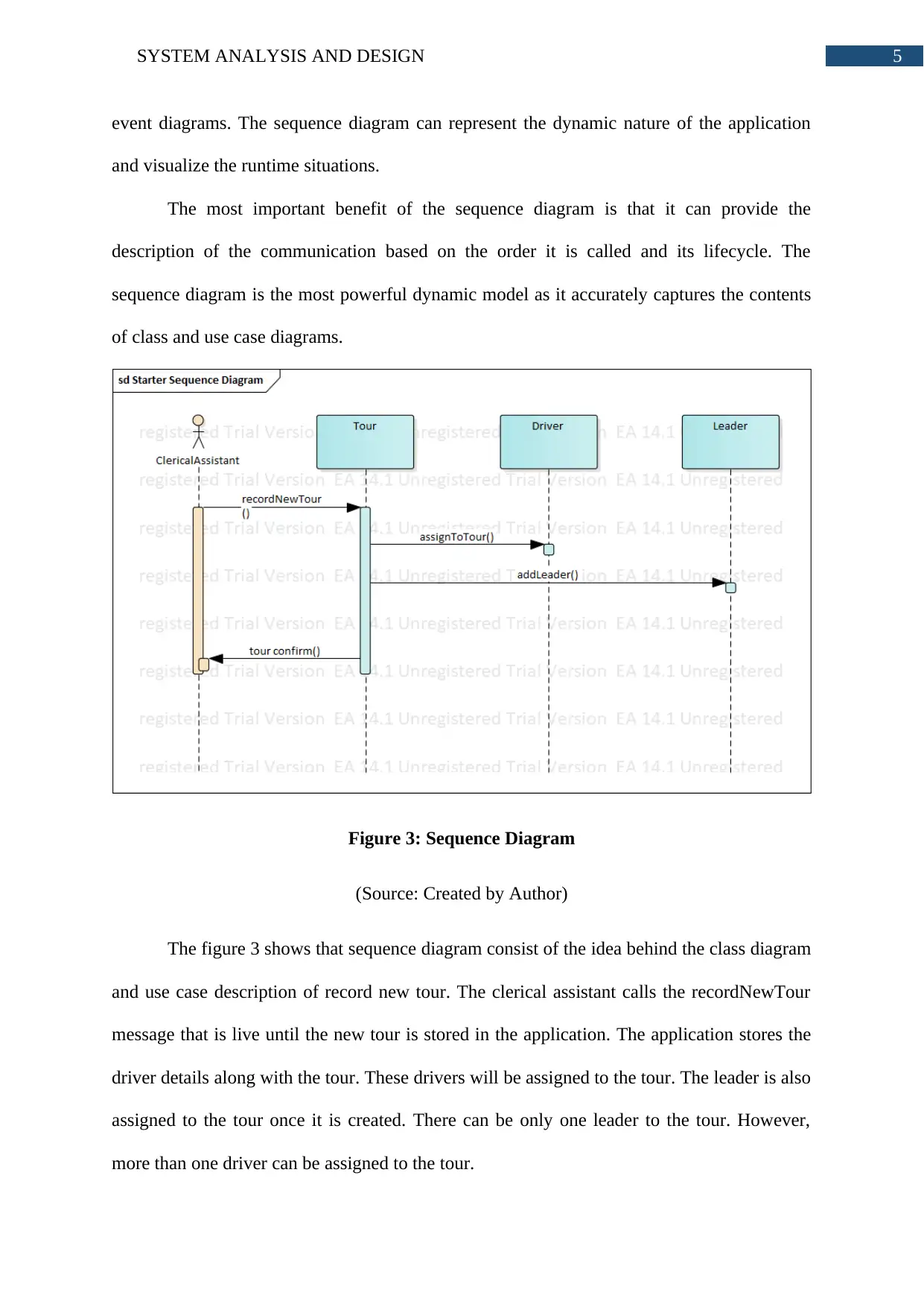
Figure 3: Sequence Diagram
(Source: Created by Author)
The figure 3 shows that sequence diagram consist of the idea behind the class diagram
and use case description of record new tour. The clerical assistant calls the recordNewTour
message that is live until the new tour is stored in the application. The application stores the
driver details along with the tour. These drivers will be assigned to the tour. The leader is also
assigned to the tour once it is created. There can be only one leader to the tour. However,
more than one driver can be assigned to the tour.
⊘ This is a preview!⊘
Do you want full access?
Subscribe today to unlock all pages.

Trusted by 1+ million students worldwide

6SYSTEM ANALYSIS AND DESIGN
Part 3: Evaluation
Computer Aided Software Engineering (CASE) tool is defined as a set of various
software applications. The applications can be considered as methods as well as tools in the
aspect of software development that are assisted by computers, these methods help in high
quality as well as error free applications. Enterprise architecture is usually a case tool that has
been developed by the Sparx System (Osman and Chaudron 2018). The tool consists of
integrated modelling platform; this platform supports systems of information technology,
embedded development and many more. CASE tools provide approaches which consist of
disciplines and check points. These approaches help analysts to develop a system; a similar
feature is included in enterprise architect in order to check project milestones at the time of
development. Enterprise architect generally offers modules that provide great performance.
Case tools are allowed to load the files along with the processing of various models without
consuming much time. Global collaboration is one more advantage that is provided by case
tool to analysts and designers. The enterprise architect stays integrated with cloud servers that
are deployable in nature; this allows people belonging to different regions all over the world,
to work on same project. This helps in making the communication in a specific project more
effective and efficient (Unhelkar 2017). The case tools of enterprise architect also offer the
simulation of various models. This is not related with the sequence diagram, communication
diagram and prepared class, but it is of great importance for few projects that are huge
compared to other projects. System analysts are allowed to bring the models designed by
them into life in order for checking the diagrams’ integrity along with effectiveness of the
logic that has been proposed by them.
Being an analyst of the system, the basic responsibility was to figure out the demands
mentioned for the application. In this particular case, the use case of record new tour that
belongs to the management systems of world tour has the complete concentration. The use
Paraphrase This Document
Need a fresh take? Get an instant paraphrase of this document with our AI Paraphraser
7SYSTEM ANALYSIS AND DESIGN
case consist of the data regarding ways by which users would be able to access that particular
system and how the system would be able to reply to the queries made by the user
(Abdessalem, Karaa and Azzouz 2016). The enterprise case tool is usually used for making
UML diagrams. UML diagrams include class diagram, sequence diagram and communication
diagram. The case tool had provided a specific option of making modules for every diagram.
The management of elements that diagrams were supposed to have was very easy as well as
accurate. This is because; the enterprise architect saves various elements that have been
declared in the diagrams present in documents. Diagrams were created as well as maintained
individually and handling of the tasks was easy. The drag as well as drop option was
followed in order to create classes. After the classes were created, attributes and operations
were created with the help of features option. Similarly, the objects had been mentioned in
the sequence and communication diagram. Creating various relationships has also been very
easy because every diagram had relationship mentioned in the same way (Storrle 2018). After
the relationship type has been chosen, from a single class or object to a different pointer had
been dragged. The names of relationships and classes were declared with the help of the
window in the middle right potion.
The mostly used tools in object oriented system projects are UML diagrams. This is
the reason that there is a huge amount of data that is available in numerous journals as well as
tutorial sites regarding the ways to use UML in an effective manner. UML can be considered
as a standard notation among the various software developers (Misbhauddin and Alshayeb
2015). The UML gives flexibility which is mostly necessary in the domain of developing
software. Modelling of the interaction and diagrams among various elements are declared for
the necessity of system that has been proposed. The architecture of designed software is
followed by using UML diagrams. UML can be considered as a modelling language that is
very rich and is allowed to capture the requirements of high level in an easy way. UML
8SYSTEM ANALYSIS AND DESIGN
diagrams allow various analysts to record both dynamic and static nature of system. Besides
behavioural and structural, structures might also be recorded with the use of UML models.
This is the reason why the designers and analysts are able to utilize the UML notations for
object oriented applications as well as for business process enhancements (Bashir, Lee and
Khan 2016). The UML also helps in finding the tracking, performance, security and other
system that are related to various requirements that are non-functional. Analysts make use of
UML in the form of visual language which can share the complete details regarding the
system of stakeholders.
⊘ This is a preview!⊘
Do you want full access?
Subscribe today to unlock all pages.

Trusted by 1+ million students worldwide

9SYSTEM ANALYSIS AND DESIGN
Bibliography:
Afanasyev, A. N., Voit, N. N., Voevodin, E. Y., &Gainullin, R. F. (2015, October). Control
of UML diagrams in designing automated systems software. In Application of Information
and Communication Technologies (AICT), 2015 9th International Conference on (pp. 285-
288). IEEE.
Alpers, S., Pilipchuk, R., Oberweis, A. and Reussner, R.H., 2018. Identifying Needs for a
Holistic Modelling Approach to Privacy Aspects in Enterprise Software Systems. ICISSP, 18,
pp.74-82.
Baresi, L., Blohm, G., Kolovos, D.S., Matragkas, N., Motta, A., Paige, R.F., Radjenovic, A.
and Rossi, M., 2015. Formal verification and validation of embedded systems: the UML-
based MADES approach. Software & Systems Modeling, 14(1), pp.343-363.
Bashir, R.S., Lee, S.P., Khan, S.U.R., Chang, V. and Farid, S., 2016. UML models
consistency management: Guidelines for software quality manager. International Journal of
Information Management, 36(6), pp.883-899.
Ben AbdessalemKaraa, W., Ben Azzouz, Z., Singh, A., Dey, N., S. Ashour, A. and Ben
Ghazala, H., 2016. Automatic builder of class diagram (ABCD): an application of UML
generation from functional requirements. Software: Practice and Experience, 46(11),
pp.1443-1458.
Chitchyan, R., Rashid, A., Sawyer, P., Garcia, A., Alarcon, M.P., Bakker, J., Tekinerdogan,
B., Clarke, S. and Jackson, A., 2015. Survey of aspect-oriented analysis and design
approaches.
Paraphrase This Document
Need a fresh take? Get an instant paraphrase of this document with our AI Paraphraser
10SYSTEM ANALYSIS AND DESIGN
Christopher, G.E. and Jack, I.E.K.E., 2016. A model of local area network based application
for Inter-office communication. In Proceedings of the World Congress on Engineering and
Computer Science (Vol. 1, pp. 19-21).
Fernández-Sáez, A.M., Genero, M., Chaudron, M.R., Caivano, D. and Ramos, I., 2015. Are
Forward Designed or Reverse-Engineered UML diagrams more helpful for code
maintenance?: A family of experiments. Information and Software Technology, 57, pp.644-
663.
Gogolla, M. and Hilken, F., 2016. Model validation and verification options in a
contemporary UML and OCL analysis tool. Modellierung 2016.
Guiochet, J., 2016. Hazard analysis of human–robot interactions with HAZOP–UML. Safety
science, 84, pp.225-237.
Kriaa, S., Pietre-Cambacedes, L., Bouissou, M. and Halgand, Y., 2015. A survey of
approaches combining safety and security for industrial control systems. Reliability
Engineering & System Safety, 139, pp.156-178.
Leemans, M. and van der Aalst, W.M., 2015, September. Process mining in software
systems: Discovering real-life business transactions and process models from distributed
systems. In 2015 ACM/IEEE 18th International Conference on Model Driven Engineering
Languages and Systems (MODELS) (pp. 44-53). IEEE.
Misbhauddin, M. and Alshayeb, M., 2015. Extending the UML use case metamodel with
behavioral information to facilitate model analysis and interchange. Software & Systems
Modeling, 14(2), pp.813-838.

11SYSTEM ANALYSIS AND DESIGN
Osman, H. and Chaudron, M.R., 2018. Correctness and Completeness of CASE Tools in
Reverse EngineeringSource Code into UML Model. GSTF Journal on Computing (JoC),
2(1).
Singh, M., Sharma, A.K. and Saxena, R., 2016. An UML+ Z framework for validating and
verifying the Static aspect of Safety Critical System. Procedia Computer Science, 85, pp.352-
361.
Storrle, H., 2018. On the impact of size to the understanding of UML diagrams. Software &
Systems Modeling, 17(1), pp.115-134.
Unhelkar, B., 2017. Software Engineering with UML. Auerbach Publications.
Yampolskiy, M., Horváth, P., Koutsoukos, X.D., Xue, Y. and Sztipanovits, J., 2015. A
language for describing attacks on cyber-physical systems. International Journal of Critical
Infrastructure Protection, 8, pp.40-52.
⊘ This is a preview!⊘
Do you want full access?
Subscribe today to unlock all pages.

Trusted by 1+ million students worldwide
1 out of 12
Related Documents
Your All-in-One AI-Powered Toolkit for Academic Success.
+13062052269
info@desklib.com
Available 24*7 on WhatsApp / Email
![[object Object]](/_next/static/media/star-bottom.7253800d.svg)
Unlock your academic potential
Copyright © 2020–2026 A2Z Services. All Rights Reserved. Developed and managed by ZUCOL.


