System Analysis and Design

Verified

Added on  2023/04/21

|11
|2011
|287
AI Summary
This study material provides an in-depth understanding of system analysis and design. It covers the use of class diagrams, communication diagrams, and sequence diagrams in system analysis and design. It also explores the benefits of using UML and enterprise architect in designing and managing systems. The material includes an evaluation of enterprise architect and its performance in system design. References and bibliography are provided for further reading.

Contribute Materials

Your contribution can guide someone’s learning journey. Share your documents today.
Document Page
Running head: SYSTEM ANALYSIS AND DESIGN
System Analysis and Design
Name of the Student
Name of the University
Author’s note:

Secure Best Marks with AI Grader

Need help grading? Try our AI Grader for instant feedback on your assignments.
Document Page
1SYSTEM ANALYSIS AND DESIGN
Table of Contents
Part 1: Use Case Realisation for the ‘Record New Tour’ Use Case...........................................2
1.1 Analysis Class Diagram:..................................................................................................2
1.2 Communication Diagram:................................................................................................3
Part 2: Sequence Diagram..........................................................................................................4
Part 3: Evaluation.......................................................................................................................6
Bibliography:..............................................................................................................................9
Document Page
2SYSTEM ANALYSIS AND DESIGN
Part 1: Use Case Realisation for the ‘Record New Tour’ Use Case
1.1 Analysis Class Diagram:
The Unified Modelling Language or UML can allow a designer to represent a system
through several models and one of these models are class diagram (Decker et al. 2016). The
class diagram is one of the most popular modelling diagram because it can document the
architecture of software. The class diagrams are easy to develop and simple to understand.
The benefits of class diagram in system analysis and design are as following. The
class diagram visualizes the general overview of system schematics (Nikulchev and
Deryugina 2016). The class diagram provide easy to understand information system data
model. Provide the structural information of the proposed system.
Document Page
3SYSTEM ANALYSIS AND DESIGN
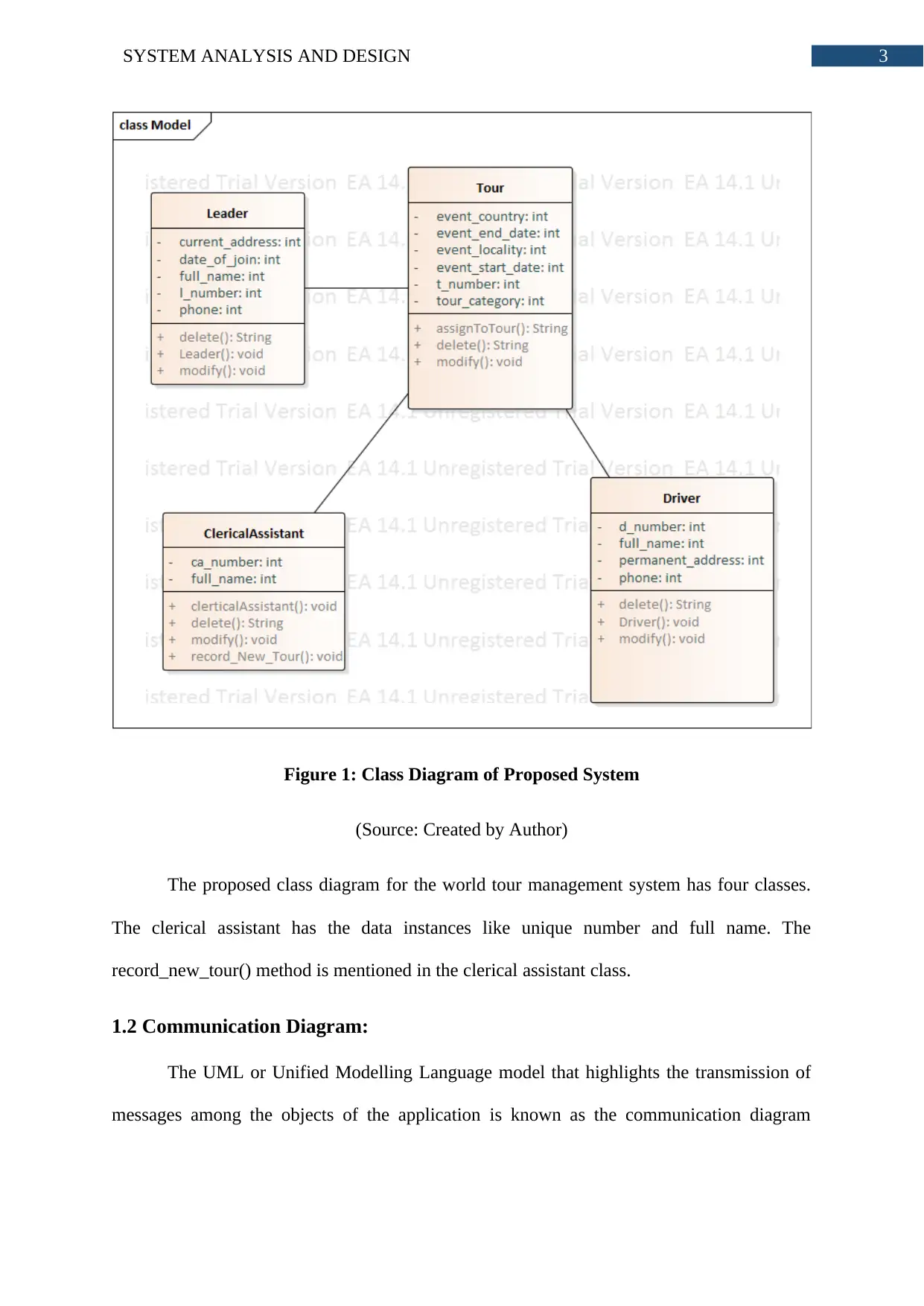
Figure 1: Class Diagram of Proposed System
(Source: Created by Author)
The proposed class diagram for the world tour management system has four classes.
The clerical assistant has the data instances like unique number and full name. The
record_new_tour() method is mentioned in the clerical assistant class.
1.2 Communication Diagram:
The UML or Unified Modelling Language model that highlights the transmission of
messages among the objects of the application is known as the communication diagram

Secure Best Marks with AI Grader

Need help grading? Try our AI Grader for instant feedback on your assignments.
Document Page
4SYSTEM ANALYSIS AND DESIGN
(Gogolla et al. 2015). The communication diagrams are also known as the collaboration
diagram. This diagram is somewhat similar to sequence diagram.
The benefits of communication diagram in system analysis and design are as
following. The communication diagram is very flexible. It is because, the communication
diagram allows inserting new objects within its two dimension environment (Dennis, Wixom
and Tegarden 2015). The communication diagrams are preferable for agile modelling
practices. Communication diagram is easy to understand and follows simple development
procedure.
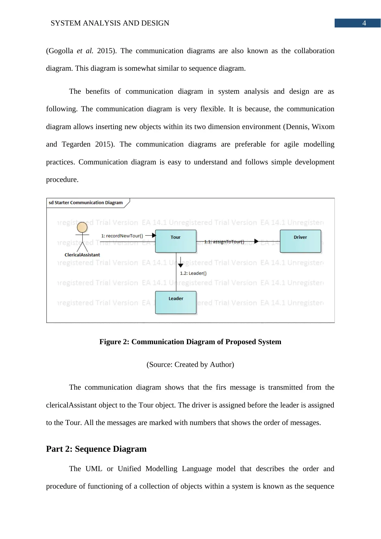
Figure 2: Communication Diagram of Proposed System
(Source: Created by Author)
The communication diagram shows that the firs message is transmitted from the
clericalAssistant object to the Tour object. The driver is assigned before the leader is assigned
to the Tour. All the messages are marked with numbers that shows the order of messages.
Part 2: Sequence Diagram
The UML or Unified Modelling Language model that describes the order and
procedure of functioning of a collection of objects within a system is known as the sequence
Document Page
5SYSTEM ANALYSIS AND DESIGN
diagram. The sequence diagram documents the new requirements of the system (Soares
2017). Therefore, it is very popular among the system developers and business analysts.
The benefits of sequence diagram in the system analysis and design are as following.
The biggest advantage of sequence diagram is that it visualizes the detailed documentation if
use case diagram (Jena, Swain and Mohapatra 2015). The sequence diagram shows
interaction among the objects based on the time and order.
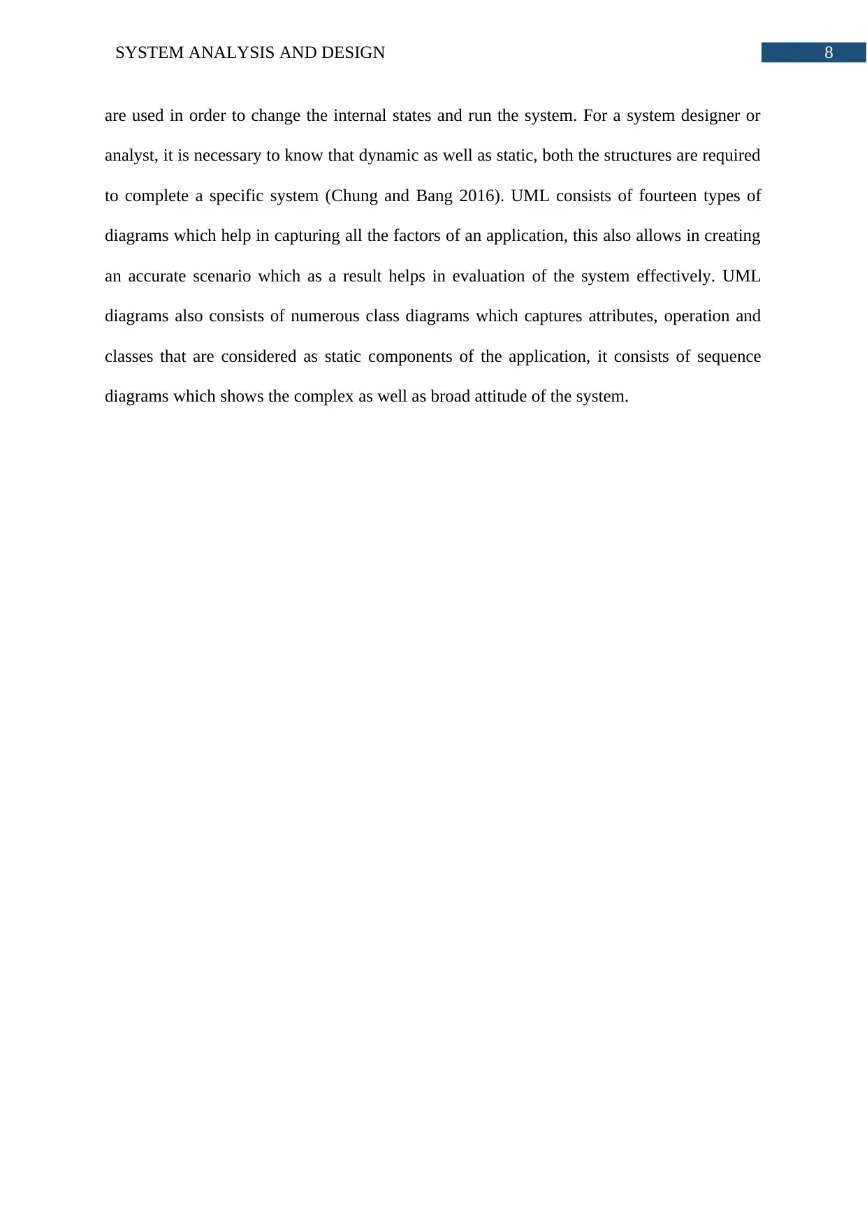
Figure 3: Sequence Diagram of Proposed System
(Source: Created by Author)
The proposed system sequence diagram shows that a loop is in the application. The
clerical assistant can add driver for more than one time. The record_new_Tour() method
initiates the whole tour record process.
Document Page
6SYSTEM ANALYSIS AND DESIGN
Part 3: Evaluation
In order to make the ICT project tasks easy, the project team uses various tools to
manage and complete tasks. The project team uses the case tool for the purpose of making the
design related activities of the project more accurate and efficient. The software engineering,
business systems, IT applications, IT system lifecycles processes are supported by the
modelling platform named enterprise architect (Osman and Chaudron 2018). The enterprise
architect has in build ability to manage system requirements. This feature of enterprise
architect allows the designing team tracking the high level application perquisites for
designing, analysing, implementation, testing and post development support. The support of
enterprise architect can be clearly seen for the models that have been produced for World
Tour Management System (Solaimani, Bouwman and Itala 2015). The enterprise architect is
capable of implementing robust tour management system. Moreover, it provides the
opportunity to the designers to maintain the system designs. The enterprise architect also has
a built-in reporting and documentation feature that allows easy and accurate representation of
tour management system UML models. The performance of the enterprise architect is better
than other conventional modelling case tools (Osman and Chaudron 2018). The time for
loading the module in the enterprise architect case tool is less than similar case tools. The
load time for developed UML modules was very fast.
The fact that complete traceability has been administered by CASE tool Enterprise
Architect, this is very important to consider during the development of system design. Along
with offering complete traceability from the design, it had also provided entire traceability in
aspect of various requirements as well as the requirements’ analysis (Bashroush et al., 2017).
This task comprised of designing only, hence the traceability was provided and utilized for
the purpose of carrying out this particular task. The aspect that weather the deployment and
development remains same has not been tested. It had various features including analyzing,

Paraphrase This Document

Need a fresh take? Get an instant paraphrase of this document with our AI Paraphraser
Document Page
7SYSTEM ANALYSIS AND DESIGN
validating and verifying the impact of various diagrams that were provided in order to
assisting during the designing of accurate ones. The authenticate information that had helped
in understanding as well as analyzing various requirements was used in equipment of the
enterprise architecture. Enterprise architecture consists of numerous features that are required
in delivering the task with accuracy.
During the designing of the application that has been proposed, analyst usually stays
worried regarding the codes, here the case tool provides the most necessary help to the
analyst by giving a finished spotlight on the design. In the use case of ‘include new tour’, the
engineering case tools allow a procedure to apply new qualifications in it (Osman and
Chaudron 2018). Case tool provides an advantage to the analyst where he can concentrate on
ways to structure UML diagrams and not on the ways how case tool would be used. This is
compulsory because originators are provided with more chances to structure as well as beak
the diagrams instead of researching about venture design. EA tool case consists of a module
of user connection which helps in empowering designing of diagrams in an effective manner.
Designing the class diagram has been very simple; including various qualities along with the
task characterization was simple as well. The case tools provide diagrams that are very
simple in nature. Case tools provide simple procedures for creating interface in to the
grouping diagram and segment diagram. Every diagram was made with precision so that the
dynamic as well as basic parts are allowed to catch consummately (Jugel et al., 2015). It
provided a perfect situation to planning and catching the chunks of knowledge of provided
business procedures of the use case.
UML provides a huge support to the system analyst and the designer by allowing the
capturing of static as well as dynamic view of the system. The basic requirements of the
application is considered as its static structure, around this the entire application is designed
and run. Whereas, the application’s dynamic behavior represents ways how static structures
Document Page
8SYSTEM ANALYSIS AND DESIGN
are used in order to change the internal states and run the system. For a system designer or
analyst, it is necessary to know that dynamic as well as static, both the structures are required
to complete a specific system (Chung and Bang 2016). UML consists of fourteen types of
diagrams which help in capturing all the factors of an application, this also allows in creating
an accurate scenario which as a result helps in evaluation of the system effectively. UML
diagrams also consists of numerous class diagrams which captures attributes, operation and
classes that are considered as static components of the application, it consists of sequence
diagrams which shows the complex as well as broad attitude of the system.
Document Page
9SYSTEM ANALYSIS AND DESIGN
Bibliography:
Bashroush, R., Garba, M., Rabiser, R., Groher, I. and Botterweck, G., 2017. Case tool
support for variability management in software product lines. ACM Computing Surveys
(CSUR), 50(1), p.14.
Chung, S. and Bang, S., 2016. Identifying knowledge, skills, and abilities (KSA) for devops-
aware server side web application with the grounded theory. Journal of Computing Sciences
in Colleges, 32(1), pp.110-116.
Decker, M.J., Swartz, K., Collard, M.L. and Maletic, J.I., 2016. A tool for efficiently reverse
engineering accurate UML class diagrams. In 2016 IEEE International Conference on
Software Maintenance and Evolution (ICSME) (pp. 607-609). IEEE.
Dennis, A., Wixom, B.H. and Tegarden, D., 2015. Systems analysis and design: An object-
oriented approach with UML. John wiley & sons.
Gogolla, M., Hamann, L., Hilken, F. and Sedlmeier, M., 2015. Modeling behavior with
interaction diagrams in a UML and OCL tool. In Behavior Modeling--Foundations and
Applications(pp. 31-58). Springer, Cham.
Jena, A.K., Swain, S.K. and Mohapatra, D.P., 2015. Test case creation from UML sequence
diagram: a soft computing approach. In Intelligent Computing, Communication and
Devices (pp. 117-126). Springer, New Delhi.
Jugel, D., Kehrer, S., Schweda, C.M. and Zimmermann, A., 2015. A decision-making case
for collaborative enterprise architecture engineering. Gesellschaft für Informatik eV.
Nikulchev, E. and Deryugina, O., 2016. Model and Criteria for the Automated Refactoring of
the UML Class Diagrams. International Journal of Advanced Computer Science and
Applications, 7(12), pp.76-79.

Secure Best Marks with AI Grader

Need help grading? Try our AI Grader for instant feedback on your assignments.
Document Page
10SYSTEM ANALYSIS AND DESIGN
Osman, H. and Chaudron, M.R., 2018. Correctness and Completeness of CASE Tools in
Reverse EngineeringSource Code into UML Model. GSTF Journal on Computing
(JoC), 2(1).
Osman, H. and Chaudron, M.R., 2018. Correctness and Completeness of CASE Tools in
Reverse EngineeringSource Code into UML Model. GSTF Journal on Computing
(JoC), 2(1).
Soares, J.A.C., 2017. Automatic Model Transformation from UML Sequence Diagrams to
Coloured Petri Nets.
Solaimani, S., Bouwman, H. and Itala, T., 2015. Networked enterprise business model
alignment: A case study on smart living. Information Systems Frontiers, 17(4), pp.871-887.
1 out of 11
circle_padding
hide_on_mobile
zoom_out_icon
[object Object]

Your All-in-One AI-Powered Toolkit for Academic Success.

Available 24*7 on WhatsApp / Email

[object Object]