System Analysis and Design: UML Modeling and CASE Tools in TMS
VerifiedAdded on 2021/11/16
|8
|1645
|496
Report
AI Summary
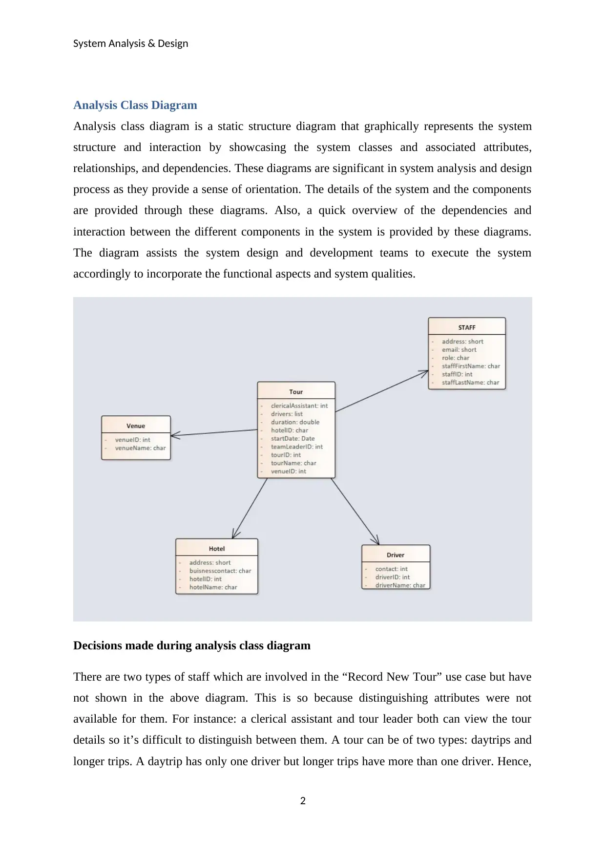
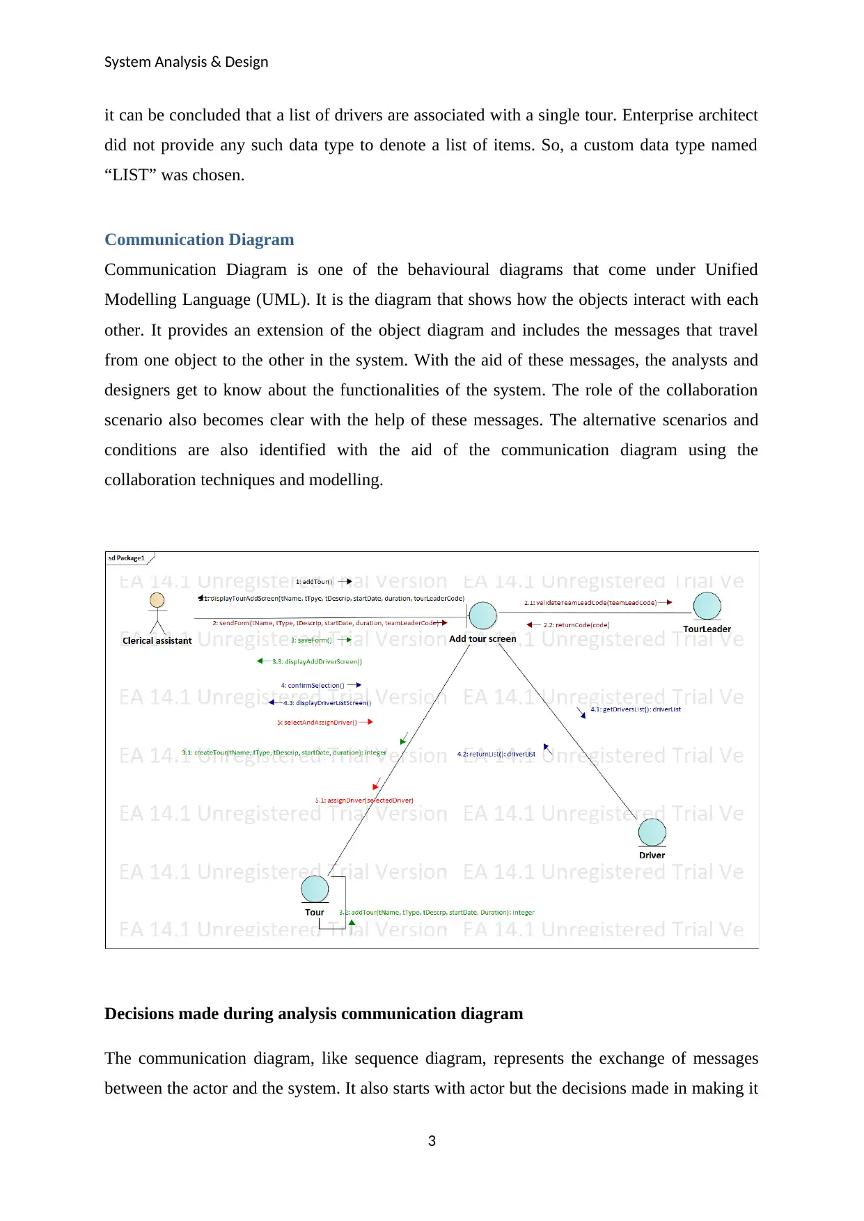
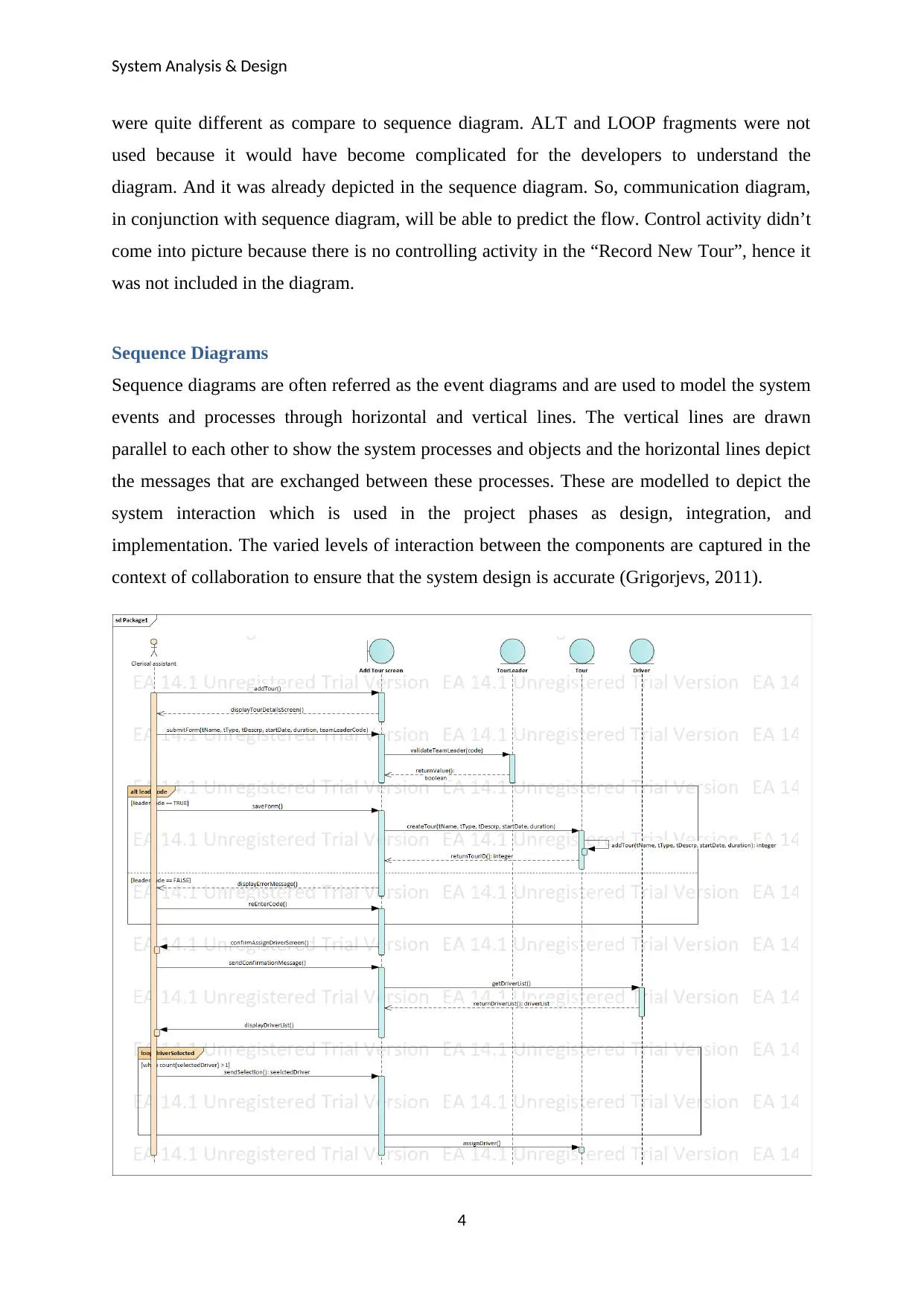
This report provides a detailed analysis and design of a system, focusing on the application of UML diagrams and CASE tools. It includes discussions on analysis class diagrams, communication diagrams, and sequence diagrams, highlighting the decisions made during their creation. The report also examines the use of CASE tools, such as Enterprise Architect, in the context of Wide World Tours' Tour Management System (TMS), emphasizing their support for analysts and designers in requirement gathering, system modeling, and change tracking. Furthermore, the document explores how UML modeling aids in system design, integration, and implementation, with specific references to use case diagrams and their role in defining system interactions. The report concludes with a list of references used in the analysis and design process.
1 out of 8
Related Documents


Your All-in-One AI-Powered Toolkit for Academic Success.
+13062052269
info@desklib.com
Available 24*7 on WhatsApp / Email
![[object Object]](/_next/static/media/star-bottom.7253800d.svg)
Copyright © 2020–2026 A2Z Services. All Rights Reserved. Developed and managed by ZUCOL.