System Design and Engineering Report: Capital Metro Light Rail Project
VerifiedAdded on 2020/03/23
|15
|3157
|210
Report
AI Summary
This report provides a comprehensive analysis of the Canberra light rail project, focusing on the design and development of a new light rail system in Canberra, Australia. The project aims to establish a 12 km route connecting Central Canberra and Gungahlin, passing through key commercial, educational, and transport hubs. The report details the preliminary design, including route type, rail car specifications, service frequency, ticketing systems, and power supply methods. It further elaborates on the detailed design, infrastructure, and development plans, including route design, infrastructure, and construction phases. The report also covers system testing, evaluation, validation, and optimization strategies, including rail and power supply tests, and the potential utilization of solar energy. This report offers valuable insights into the engineering and system design aspects of the Canberra light rail project.
Running Head: SYSTEM SCIENCE AND ENGINEERING
System Science and Engineering: Capital Metro Project
Name of the Student
Name of the University
System Science and Engineering: Capital Metro Project
Name of the Student
Name of the University
Paraphrase This Document
Need a fresh take? Get an instant paraphrase of this document with our AI Paraphraser
1SYSTEM SCIENCE AND ENGINEERING
Executive Summary
This project is based on the development of a new light rail system in the city of Canberra,
Australia. The two terminal points of the route will be Central Canberra and Gungahlin and the
entire route will be 12 km long. The main focus for the route design is that the route will pass
through all the important commercial and educational sectors as well as the main points of other
transport terminals like bus depot, railway stations, ferry ghats and airport. In this report, the
different design features of the proposed light rail system have been critically analysed and
published.
2SYSTEM SCIENCE AND ENGINEERING
Table of Contents
1.0 Introduction................................................................................................................................3
2.0 Preliminary Design....................................................................................................................3
3.0 Detailed Design and Development............................................................................................5
4.0 System Test, Evaluation, Validation and Optimization.............................................................7
4.1 System Test............................................................................................................................7
4.2 Evaluation..............................................................................................................................8
4.3 Validation..............................................................................................................................9
4.4 Optimization........................................................................................................................10
5.0 Conclusion...............................................................................................................................10
References......................................................................................................................................12
⊘ This is a preview!⊘
Do you want full access?
Subscribe today to unlock all pages.

Trusted by 1+ million students worldwide
3SYSTEM SCIENCE AND ENGINEERING
1.0 Introduction
Canberra is the capital and one of the biggest cities in Australia. Due to the extreme rush
of the passengers during the peak office hours, the traffic gets extremely congested and the
movement becomes slow considerably. In order to solve this situation, the government has
proposed to develop a light rail system that will be able to reduce the load of passengers using
other transportation modes (Birdsall 2016). However, for the implementation purpose, the
project must go through a large number of phases spanning over 20 years of design, development
and hard work of all involved personnel. According to the proposed plan, the light rail system
will be able to reduce vehicular traffic by 30% in the first five years of operation.
In this report, the detailed plan and the design aspects of the project have been critically
analysed and discussed.
2.0 Preliminary Design
In this project, a new light rail system will be developed for Canberra where it is
expected to lighten the excessive load of passengers in other transports mainly during the rush
office hours. The preliminary design features of the light rail system will be as follows.
Initial Purpose – The initial purpose to be fulfilled through this project is to reduce the
heavy traffic from other transport vehicles like cars and buses during the rush hours. Hence, the
route must be placed such that it passes through the main arterial zones within the commercial
sector as well as some of the important residential zones so that the commuters can easily reach
their destinations from their living places during the office hours (Ney and Gray 2014). Hence,
the initial purpose of the project is to design the route through the most populated and the
Paraphrase This Document
Need a fresh take? Get an instant paraphrase of this document with our AI Paraphraser
4SYSTEM SCIENCE AND ENGINEERING
important commercial areas between which, the daily numbers of commuters reach the peak
during office hours.
Route Type and Rail Cars – The proposed route type is normal electrified route i.e. the
tracks will be normal broad gauge rail with overhead wires that will supply power to the railcars
through a pantograph. The route will be placed throughout the middle of the roadway with
specific station chambers after every 500 metres where the passengers will be allowed to board
or leave the rail cars (Hensher 2016). As per the proposed plan, each light rail vehicle will have 3
rail cars having maximum capacity of 40 people and hence, one vehicle will be able to transport
120 people at a time. The last car of the vehicle will have a pantograph that will be directly
attached with the overhead supply wire.
Service and Tickets – As per the new proposed plan, during rush hours, the frequency of
the rail cars will be between 2 to 3 minutes and during lean hours and holidays, it will be 10 to
15 minutes. The high frequency of services will ensure clearance of 120 per 2 minutes i.e. 3600
passengers per hour. This will significantly reduce the load of passengers on other vehicles. In
order to bear the costs of the services, a ticketing system will be applied where the passengers
will have to pay a certain amount of money for the distance they will travel in the train. The
passengers will be able to buy tickets on spot from the station chambers or they can buy the
OPEL cards that they can recharge every month (Ho, Hensher and Mulley 2015). When the card
holders will board and leave the train, they will just need to swipe the card through an electronic
box inside the train and the travel value will be automatically deducted from his account. The
proposed fares start from AU$ 1 for every 1 Km of travel although this will be subject to change
based on market inflation and other factors.
5SYSTEM SCIENCE AND ENGINEERING
Power Supply – In order to prevent environment pollution as well as save costs of fossil
fuels, the proposed power supply is electricity that will be transferred from the overhead wires to
the rail cars through the pantograph. Although the initial installation costs will be extremely
high, the operational and maintenance costs will be extremely low compared to other power
supplies. However, plans have also been made to utilize solar energy in the future in order save
further electric power costs.
3.0 Detailed Design and Development
The detailed design and development features of the new proposed light rail system are as
follows.
Route Design – As per the proposed plan, the entire route of the light rail will be
designed such that it passes through all the busiest sectors of the city. The two terminal points of
the route will be Central Canberra and Gungahlin and the entire route will be 12 km long. The
main focus for the route design is that the route will pass through all the important commercial
and educational sectors as well as the main points of other transport terminals like bus depot,
railway stations, ferry ghats and airport (Downs, Cassels and Ericksen 2014). The main reason
behind this is that the objective of the project is to transport passengers such that when they get
off the light rail, they can easily reach their work places or other modes of transport. Hence, the
light rail will be connected with every possible transit points as well as commercial houses.
Infrastructure Design – On the light rail route, each of the light rail vehicle will contain
3 coaches or rail cars connected together. There are many large companies like Mitsubishi Corp,
Aberdeen Infrastructure Investments, John Holland and DB International among others that are
trying the get contract for building the rail cars. According to the proposed features of the rail
⊘ This is a preview!⊘
Do you want full access?
Subscribe today to unlock all pages.

Trusted by 1+ million students worldwide
6SYSTEM SCIENCE AND ENGINEERING
cars, each rail car coach will have capacity for maximum 40 people (25 sitting and 15 standing)
and hence, 120 in total for one vehicle. Air conditioning system will be available inside each car
and the seats will be such that they provide maximum comfort to the passengers. For the
standing passengers, support rods will also be included (Burke, Currie and Delbosc 2014). Each
railcar will be driven by electricity and from third coach of each rail car, a pantograph will
connect to the overhead wire from which, it will provide electric power to the entire vehicle. It
has also been proposed that in the near future, solar panels will be added on the roof tops of each
light rail vehicle.
Depots and Power Supply – Currently, two depots have been proposed at the two
terminals of the route where the rail cars can be repaired or serviced. Moreover, the depots will
also allow the rail cars to turn around for a reverse trip. For the power supply, two substations
have been proposed to be built at the two terminals from where; the power will be supplied to the
overhead wires. However, further expansion of route and addition of more depots have also been
proposed.
Development Plan – The development is based on the construction of the light rail route
and running of the railcars on the route. For that purpose, the route will first be designed using
maps and estimations. After that, repeated survey of the entire route area will be needed to be
done in order to check for the soil quality and the terrain. Since Canberra is mainly a rugged
terrain, laying of the rail tracks will be a difficult task. Finally, excavation process will be carried
out for the entire 12 Km route. During this time, the convenience of the traffic through this roads
will be compromised and severe traffic jams in the rush hours are expected during the excavation
of the route (Mulley, Tsai and Ma 2015). After the excavation is done, the rails will be laid and
the depots will be built along with the stations each 500 metres apart. After that, the overhead
Paraphrase This Document
Need a fresh take? Get an instant paraphrase of this document with our AI Paraphraser
7SYSTEM SCIENCE AND ENGINEERING
line posts will be placed and the overhead wires will be connected. The entire project will be
completed in three phases, each of the phases being 6 years long as per estimations.
4.0 System Test, Evaluation, Validation and Optimization
4.1 System Test
System test follows the construction process and in this phase, a number of tests need to
be conducted in order to ensure the route is ready to be operational. The system tests will include
the following aspects.
Rail Test – First, the rails will be tested for weight and longevity i.e. it will be tested to
see whether it will be able to support the weight of the light rail cars at a continuous basis for a
long amount of time. Moreover, it will also be tested to see whether the land below the rails is
not eroded off while the rail is under operation.
Power Supply Test – In this test, it will be seen whether the power supply is sufficient
through the overhead wires or not. Moreover, it will also be tested to ensure sufficient insulations
are provided at each support pole throughout the entire route.
Vehicles Test – The final test will be conducted on the vehicles that will be used as the
rail cars. The tests will be conducted to ensure there are no internal faults, the bodies of the cars
are strong and the entire car has very high longevity.
8SYSTEM SCIENCE AND ENGINEERING
4.2 Evaluation
The evaluation process follows directly from the system testing process. The entire
evaluation process should be based on a set of certain standards that should be pre-set before the
initiation of the project. These standards help to maintain a certain quality of the project.
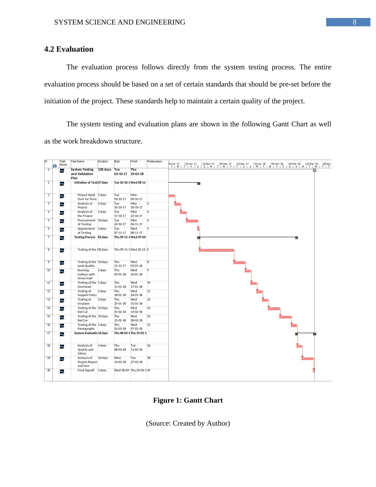
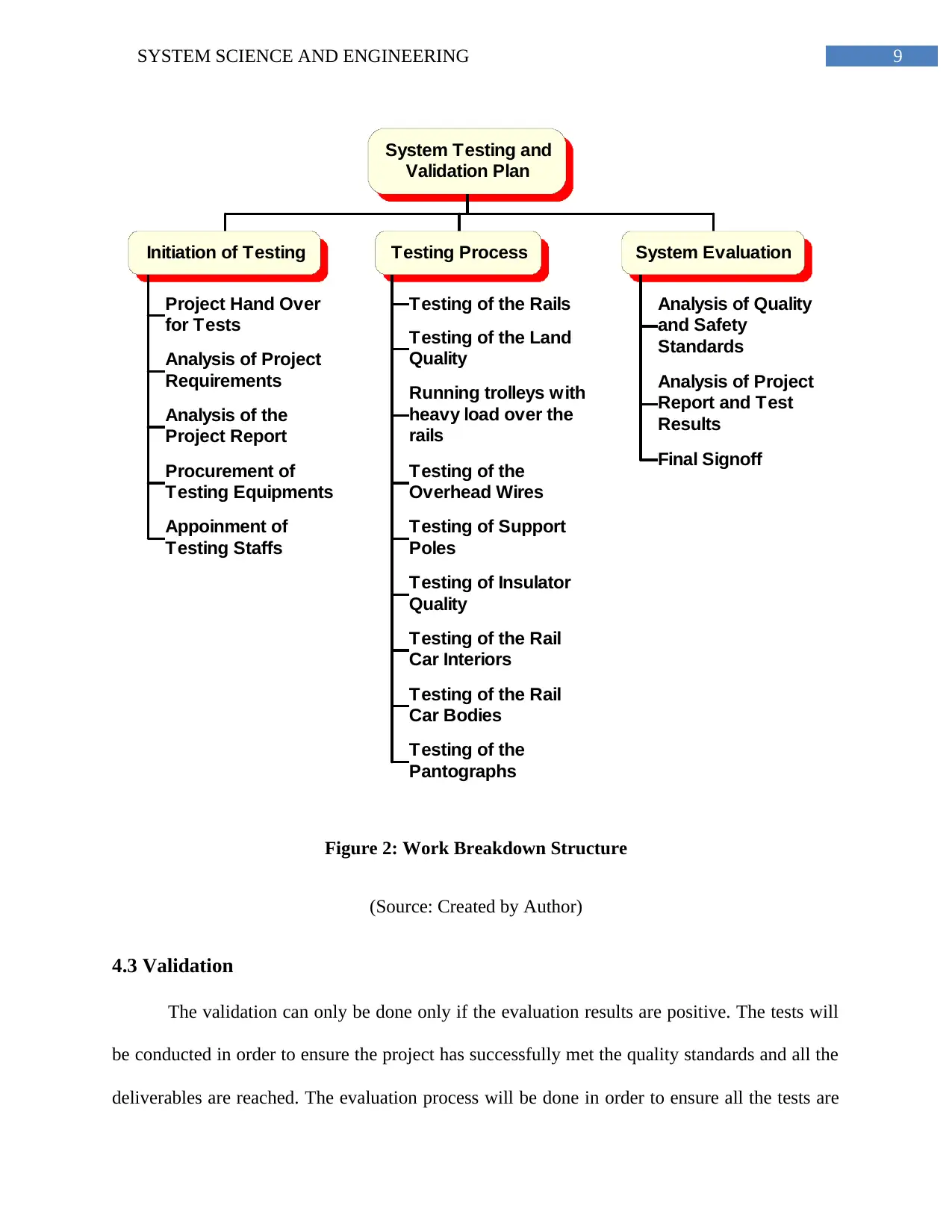
The system testing and evaluation plans are shown in the following Gantt Chart as well
as the work breakdown structure.
ID Task
Mode
Task Name Duration Start Finish Predecessors
0 System Testing
and Validation
Plan
128 days Tue
03-10-17
Thu
29-03-18
1 Initiation of Testing27 days Tue 03-10-17Wed 08-11-17
2 Project Hand
Over for Tests
5 days Tue
03-10-17
Mon
09-10-17
3 Analysis of
Project
Requirements
5 days Tue
10-10-17
Mon
16-10-17
2
4 Analysis of
the Project
Report
5 days Tue
17-10-17
Mon
23-10-17
3
5 Procurement
of Testing
Equipments
10 days Tue
24-10-17
Mon
06-11-17
4
6 Appoinment
of Testing
Staffs
2 days Tue
07-11-17
Wed
08-11-17
5
7 Testing Process 85 days Thu 09-11-17Wed 07-03-18
8 Testing of the Rails30 days Thu 09-11-17Wed 20-12-176
9 Testing of the
Land Quality
10 days Thu
21-12-17
Wed
03-01-18
8
10 Running
trolleys with
heavy load
over the rails
5 days Thu
04-01-18
Wed
10-01-18
9
11 Testing of the
Overhead
Wires
5 days Thu
11-01-18
Wed
17-01-18
10
12 Testing of
Support Poles
5 days Thu
18-01-18
Wed
24-01-18
11
13 Testing of
Insulator
Quality
5 days Thu
25-01-18
Wed
31-01-18
12
14 Testing of the
Rail Car
Interiors
10 days Thu
01-02-18
Wed
14-02-18
13
15 Testing of the
Rail Car
Bodies
10 days Thu
15-02-18
Wed
28-02-18
14
16 Testing of the
Pantographs
5 days Thu
01-03-18
Wed
07-03-18
15
17 System Evaluation16 days Thu 08-03-18Thu 29-03-18
18 Analysis of
Quality and
Safety
Standards
4 days Thu
08-03-18
Tue
13-03-18
16
19 Analysis of
Project Report
and Test
Results
10 days Wed
14-03-18
Tue
27-03-18
18
20 Final Signoff 2 days Wed 28-03-18Thu 29-03-1819
T W T F S S M T W T F S S M T W T F S S M T W T F
02 Oct '17 23 Oct '17 13 Nov '17 04 Dec '17 25 Dec '17 15 Jan '18 05 Feb '18 26 Feb '18 19 Mar '18 09 Apr '18
Figure 1: Gantt Chart
(Source: Created by Author)
⊘ This is a preview!⊘
Do you want full access?
Subscribe today to unlock all pages.

Trusted by 1+ million students worldwide
9SYSTEM SCIENCE AND ENGINEERING
System Testing and
Validation Plan
Initiation of Testing
Project Hand Over
for Tests
Analysis of Project
Requirements
Analysis of the
Project Report
Procurement of
Testing Equipments
Appoinment of
Testing Staffs
Testing Process
Testing of the Rails
Testing of the Land
Quality
Running trolleys with
heavy load over the
rails
Testing of the
Overhead Wires
Testing of Support
Poles
Testing of Insulator
Quality
Testing of the Rail
Car Interiors
Testing of the Rail
Car Bodies
Testing of the
Pantographs
System Evaluation
Analysis of Quality
and Safety
Standards
Analysis of Project
Report and Test
Results
Final Signoff
Figure 2: Work Breakdown Structure
(Source: Created by Author)
4.3 Validation
The validation can only be done only if the evaluation results are positive. The tests will
be conducted in order to ensure the project has successfully met the quality standards and all the
deliverables are reached. The evaluation process will be done in order to ensure all the tests are
Paraphrase This Document
Need a fresh take? Get an instant paraphrase of this document with our AI Paraphraser
10SYSTEM SCIENCE AND ENGINEERING
done and all the test results are positive. Finally, the validation process will done to sign off the
entire project and green signal will be given to progress further in the operational field.
4.4 Optimization
Optimization processes are generally done in order to further enhance the quality of the
project. In this particular project, there are two optimization plans. These are as follows.
Utilization of Solar Energy – It has been proposed that in the near future, solar energy
will be utilized in order to reduce the power supply costs of the light rail system. For this
purpose, solar panels will be installed on the roof tops of the rail cars and will be connected to
the main circuit.
New Substations and Terminal Depots – In order to improve the power supply to the
overhead wires, new substations will be further added at two different points of the route.
Moreover, in order to accommodate more numbers of cars, two new depots will be further built.
5.0 Conclusion
In this report, the detailed plan and the design aspects of the project have been critically
analysed and discussed. As per the project details, a new light rail system will be developed for
Canberra where it is expected to lighten the excessive load of passengers in other transports
mainly during the rush office hours. As per the proposed plan, the entire route of the light rail
will be designed such that it passes through all the busiest sectors of the city. The two terminal
points of the route will be Central Canberra and Gungahlin and the entire route will be 12 km
long. The initial purpose to be fulfilled through this project is to reduce the heavy traffic from
other transport vehicles like cars and buses during the rush hours. Hence, the route must be
11SYSTEM SCIENCE AND ENGINEERING
placed such that it passes through the main arterial zones within the commercial sector as well as
some of the important residential zones so that the commuters can easily reach their destinations
from their living places during the office hours. The main focus for the route design is that the
route will pass through all the important commercial and educational sectors as well as the main
points of other transport terminals like bus depot, railway stations, ferry ghats and airport.
⊘ This is a preview!⊘
Do you want full access?
Subscribe today to unlock all pages.

Trusted by 1+ million students worldwide
1 out of 15
Related Documents
Your All-in-One AI-Powered Toolkit for Academic Success.
+13062052269
info@desklib.com
Available 24*7 on WhatsApp / Email
![[object Object]](/_next/static/media/star-bottom.7253800d.svg)
Unlock your academic potential
Copyright © 2020–2026 A2Z Services. All Rights Reserved. Developed and managed by ZUCOL.


