Prestressed Concrete Box Girder Analysis and Design
Abstract, Introduction, Background & Theory, Procedure, Results & Discussions, Figures and Tables, Meshing, Convergence
21 Pages4159 Words289 Views
Added on 2023-04-11
About This Document
This paper analyzes a box girder section with and without prestressing force using finite element modeling. The effects of external tendons are converted into equivalent nodal loads. Suitable for civil constructions like bridges.
Prestressed Concrete Box Girder Analysis and Design
Abstract, Introduction, Background & Theory, Procedure, Results & Discussions, Figures and Tables, Meshing, Convergence
Added on 2023-04-11
ShareRelated Documents
Table of Contents
Introduction.................................................................................................................................................2
2. Literature review.....................................................................................................................................2
3. Materials And Properties.........................................................................................................................3
4. Methodology..........................................................................................................................................3
4.1. Finite element modelling..................................................................................................................3
4.1.1. Formulation of model................................................................................................................3
4. Technique................................................................................................................................................5
4.1. Limited component demonstrating..................................................................................................5
4.1.1. Definition of model....................................................................................................................5
4.1.2. Loading pattern.........................................................................................................................5
5. Fundamentals..........................................................................................................................................7
6. NUMERICAL ANALYSIS BY USING ANSYS..................................................................................................7
6.1 Basic strides of limited component investigation:.............................................................................7
6.2 Numerical Approach for Transverse Vibration of Fixed Free Beam:..................................................7
6.3 Portrayal of the limited component technique:................................................................................8
6.3 Imperative highlights of limited component strategy coming up next are the fundamental
highlights of the limited component technique:.....................................................................................8
6.5 FEA Results.......................................................................................................................................8
7. Meshing...................................................................................................................................................9
8. Overall Results.........................................................................................................................................9
9. CONCLUSION.........................................................................................................................................10
10. ACKNOWLEDGEMENTS........................................................................................................................11
11. Bibliography.........................................................................................................................................11
Introduction
Concrete is the most widely used material in construction industry. But sometimes concrete
fails to serve its purpose in structures and so prestressing technique is introduced. A
prestressed concrete structure is different from a conventional reinforced cement concrete
structure due to the application of an initial load on the structure prior to its use.
Prestressing is the introduction of a compressive force to the concrete to counteract the
stresses that will result from applied loads. Pre tensioning and post tensioning are two methods
of introducing prestressing to a concrete. Post tensioning is the process of acquainting
compressive force to the concrete after the concrete is casted. This is done by placing high
tensile steel PC Strand tendons in a desired profile. Then the tendons are stressed and locked
with anchors. Post tensioning is usually carried out at a project site. Post tensioning is getting
popular in civil constructions, example are roads, bridges, railways, tunnels, dams,
containment tanks, reservoirs, underground constructions, foundations, buildings, industrial
facilities, air & sea ports, special structures or any form of prestressed concrete structures
etc. As mentioned in above examples prestressing is suitable for bridges, so it is required to
analyse and design for the same. Box girder bridges are widely used now-a-days for
construction of bridges efficiently and economically. In this paper an attempt is made to
analyse a box girder section with and without prestressing force. The section so choose is ASBI
1800mm deep Type 1 segmental box girders of 9m width. Loadings on the girder so
considered are as per the IRC 006-2014 code i.e., moving loads class considered is Class „A‟.
To analyse manually a box girder is itself is a challenge, so to ease the analysis process finite
element approach is considered to be fair. The box girder is modelled in finite element
software ANSYS Workbench and analysed for deflection and stresses. The effects of
external tendons are converted into equivalent nodal loads.
2. Literature review
1. In the live load results of prestressed girder the distribution factors from the AASHTO LRFD
specifications were significantly higher than those calculated from the calibrated FEM. It was
also 2. Concluded that the parapets affected the magnitude of the distribution factors. By
excluding the parapets from the model, the exterior girder had distribution factors that where 20
to 25% lower than those when the parapets were included. 3. The loss of prestress during the life
span will be the only cause of deflection. The magnitude of the prestressing force, its
eccentricity, and its geometry can be selected such that the deflection be negative (camber)
immediately after prestressing, becoming a positive value at the end of the life span. 4. Tendons
along the top slab, tendons along the bottom slab, and combined tendons. To enhance the
efficiency of backup external tendons to control deflection. the increment of mid span deflection
tends to be stable at 10 years after completing the bridge, and the difference between the mean
value and the lower limit of the 95%confidence intervals of the increment of mid span deflection
is 74 mm. by applying backup tendons technique the deflection reduced.
3. Materials And Properties
Concrete of M40 grade is adopted to the box girder. The below engineering data are used
from the ANSYS library sources. Table 1 Material properties of concrete
4. Methodology
4.1. Finite element modelling
4.1.1. Formulation of model
As mentioned earlier, ANSYS software is used for analysis of box girder section. The section
properties so considered are as per AASTHO and ASBI. A Type 1 segmental box girder of
1800mm depth and 9000mm width is adopted with 2 lanes of 32m span.
Fig. 1. Cross section of box girder
Fig. 2. FEA model in ANSYS
Fig. 2. FEA model in ANSYS
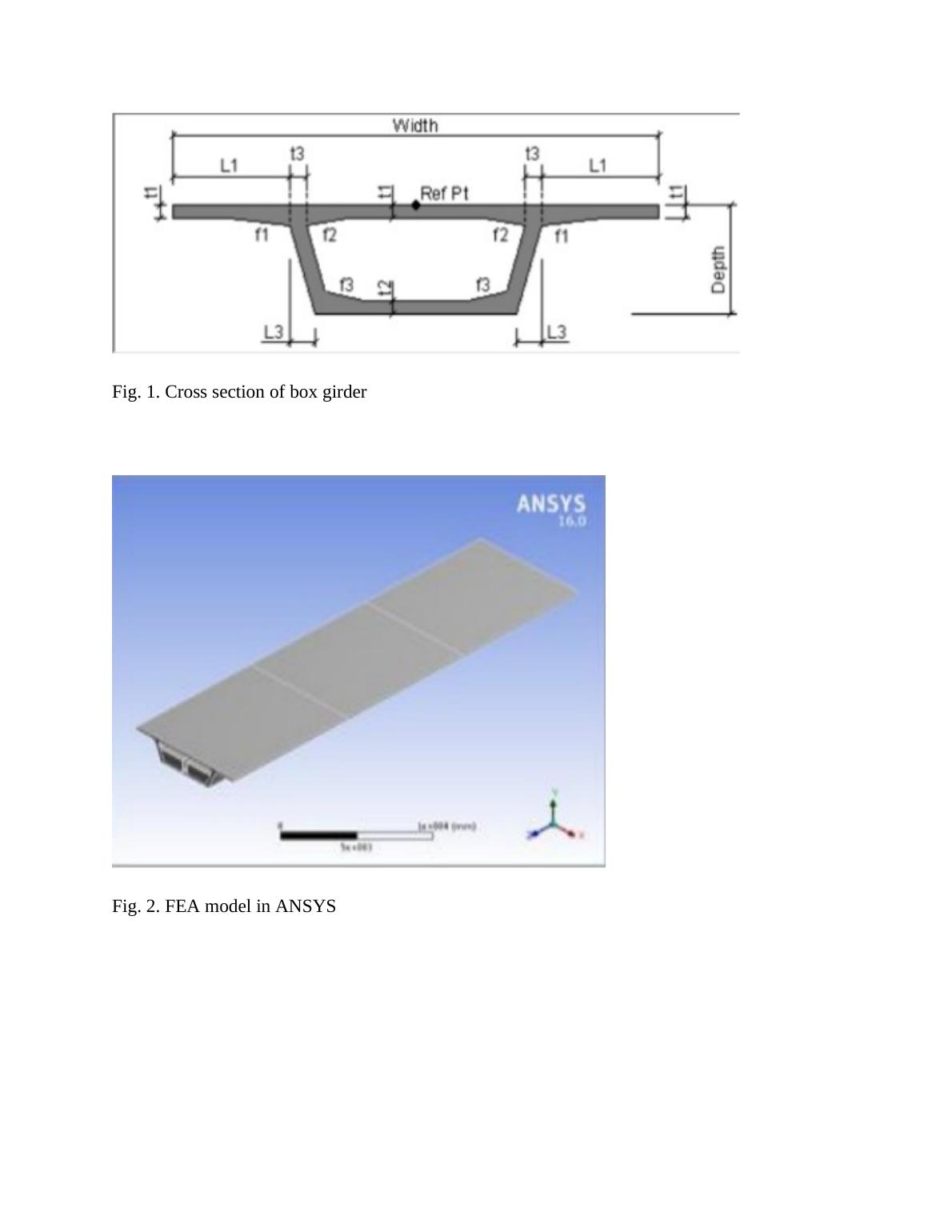
The above FEA model is created using ANSYS considering the section and material properties.
Presentation Concrete is the most generally utilized material in development industry. In any
case, now and then cement neglects to fill its need in structures thus prestressing system is
presented. A prestressed solid structure is not quite the same as an ordinary fortified bond solid
structure because of the utilization of an underlying burden on the structure before its utilization.
Prestressing is the acquaintance of a compressive power with the solid to neutralize the anxieties
that will result from connected burdens. Pre tensioning and post tensioning are two strategies for
acquainting prestressing with a solid. Post tensioning is the way toward familiarizing
compressive power to the solid after the solid is threw. This is finished by putting high pliable
steel PC Strand ligaments in an ideal profile. At that point the ligaments are pushed and bolted
with grapples. Post tensioning is typically done at a task site. Post tensioning is getting famous in
common developments, model are streets, spans, railroads, burrows, dams, regulation tanks,
repositories, underground developments, establishments, structures, mechanical offices, air and
ocean ports, uncommon structures or any type of prestressed solid structures and so on. As
referenced in above precedents prestressing is appropriate for scaffolds, so it is required to
examine and structure for the equivalent. Box brace spans are generally utilized now-a-days for
development of scaffolds productively and monetarily. In this paper an endeavor is made to
investigate a crate support segment with and without prestressing power. The area so pick is
ASBI 1800mm profound Type 1 segmental box braces of 9m width. Loadings on the brace so
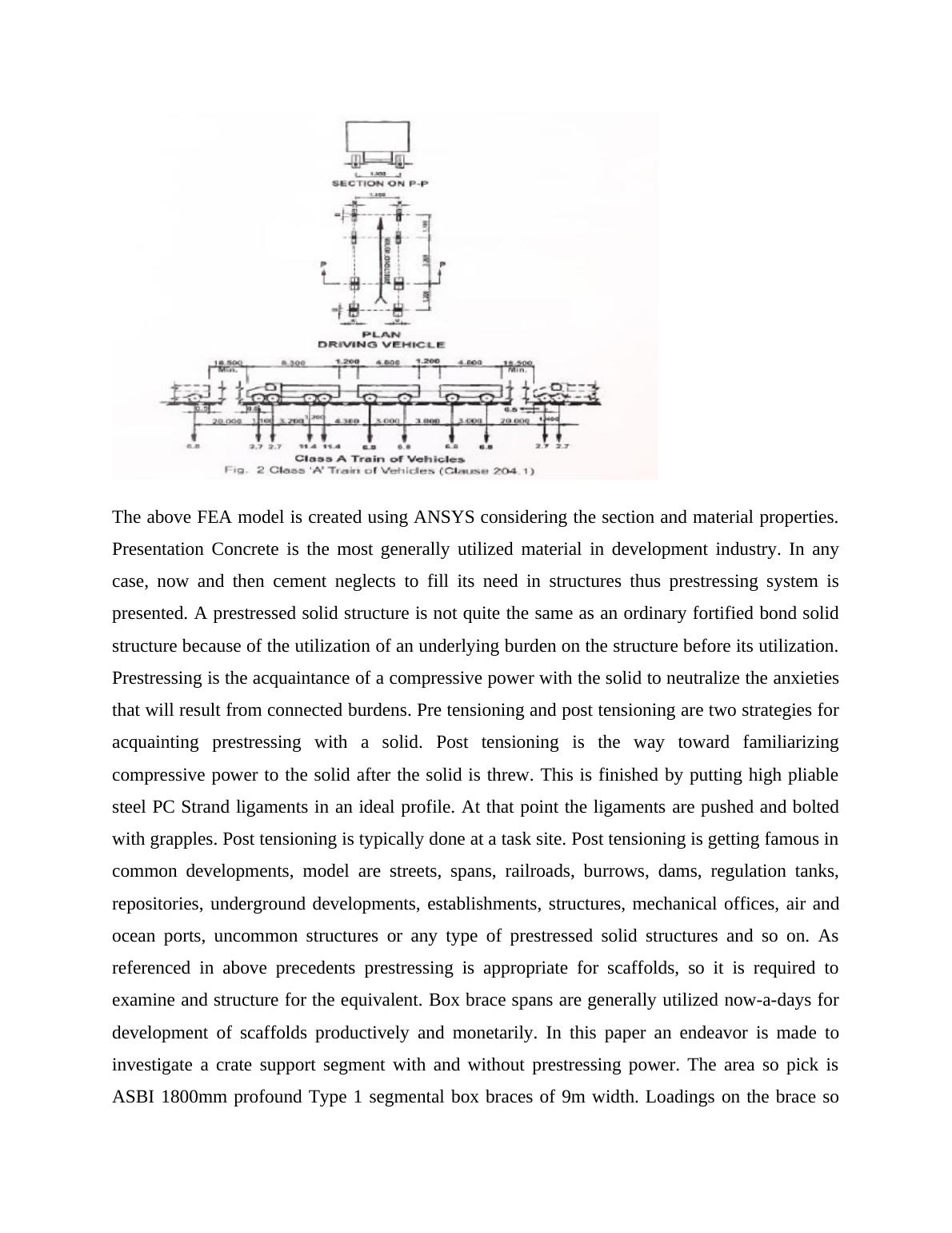
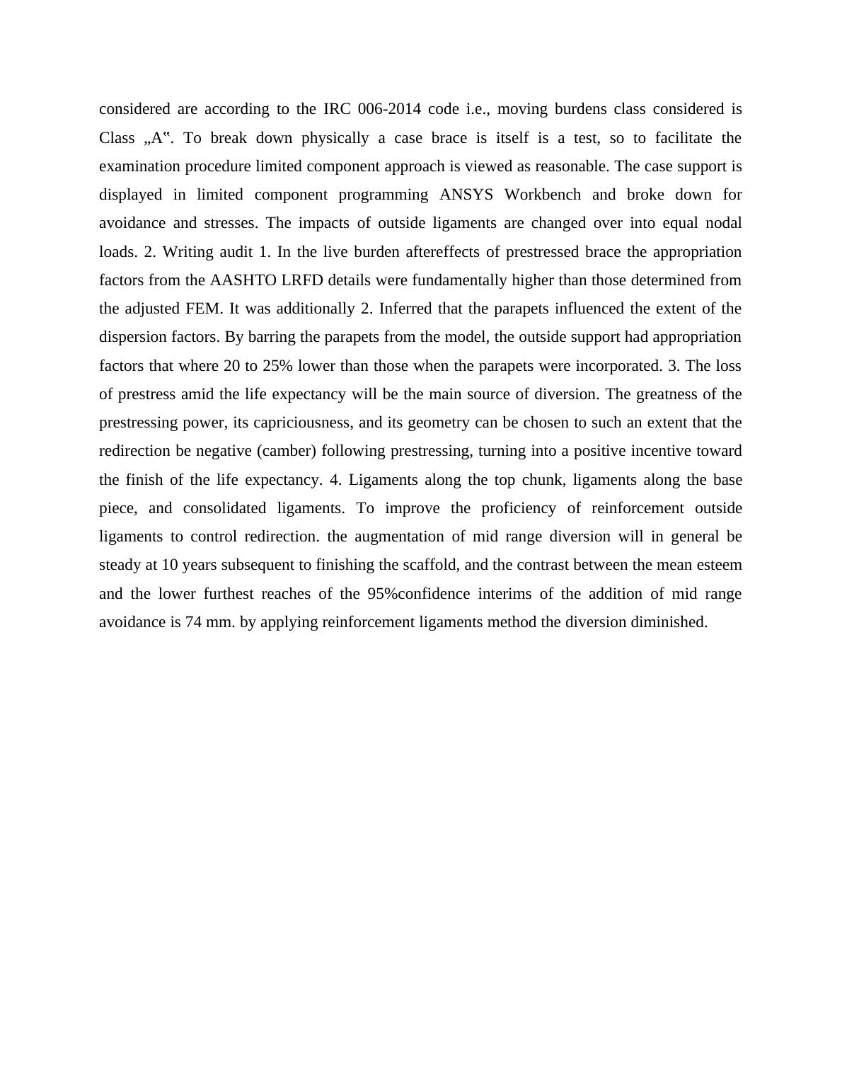
considered are according to the IRC 006-2014 code i.e., moving burdens class considered is
Class „A‟. To break down physically a case brace is itself is a test, so to facilitate the
examination procedure limited component approach is viewed as reasonable. The case support is
displayed in limited component programming ANSYS Workbench and broke down for
avoidance and stresses. The impacts of outside ligaments are changed over into equal nodal
loads. 2. Writing audit 1. In the live burden aftereffects of prestressed brace the appropriation
factors from the AASHTO LRFD details were fundamentally higher than those determined from
the adjusted FEM. It was additionally 2. Inferred that the parapets influenced the extent of the
dispersion factors. By barring the parapets from the model, the outside support had appropriation
factors that where 20 to 25% lower than those when the parapets were incorporated. 3. The loss
of prestress amid the life expectancy will be the main source of diversion. The greatness of the
prestressing power, its capriciousness, and its geometry can be chosen to such an extent that the
redirection be negative (camber) following prestressing, turning into a positive incentive toward
the finish of the life expectancy. 4. Ligaments along the top chunk, ligaments along the base
piece, and consolidated ligaments. To improve the proficiency of reinforcement outside
ligaments to control redirection. the augmentation of mid range diversion will in general be
steady at 10 years subsequent to finishing the scaffold, and the contrast between the mean esteem
and the lower furthest reaches of the 95%confidence interims of the addition of mid range
avoidance is 74 mm. by applying reinforcement ligaments method the diversion diminished.
End of preview
Want to access all the pages? Upload your documents or become a member.
Related Documents
Prestressed Concrete Designlg...
|5
|620
|361
Finite Element Analysis of Truss Structure using MATLABlg...
|5
|1586
|168