Alloys in Laser Cladding
VerifiedAdded on 2023/01/12
|37
|8539
|33
AI Summary
This document provides information on different alloys used in laser cladding, including cobalt-based alloys and nickel-based alloys. It discusses the applications and properties of each alloy and provides details on their composition. The document also includes a case study on laser cladding of cobalt alloy.
Contribute Materials
Your contribution can guide someone’s learning journey. Share your
documents today.
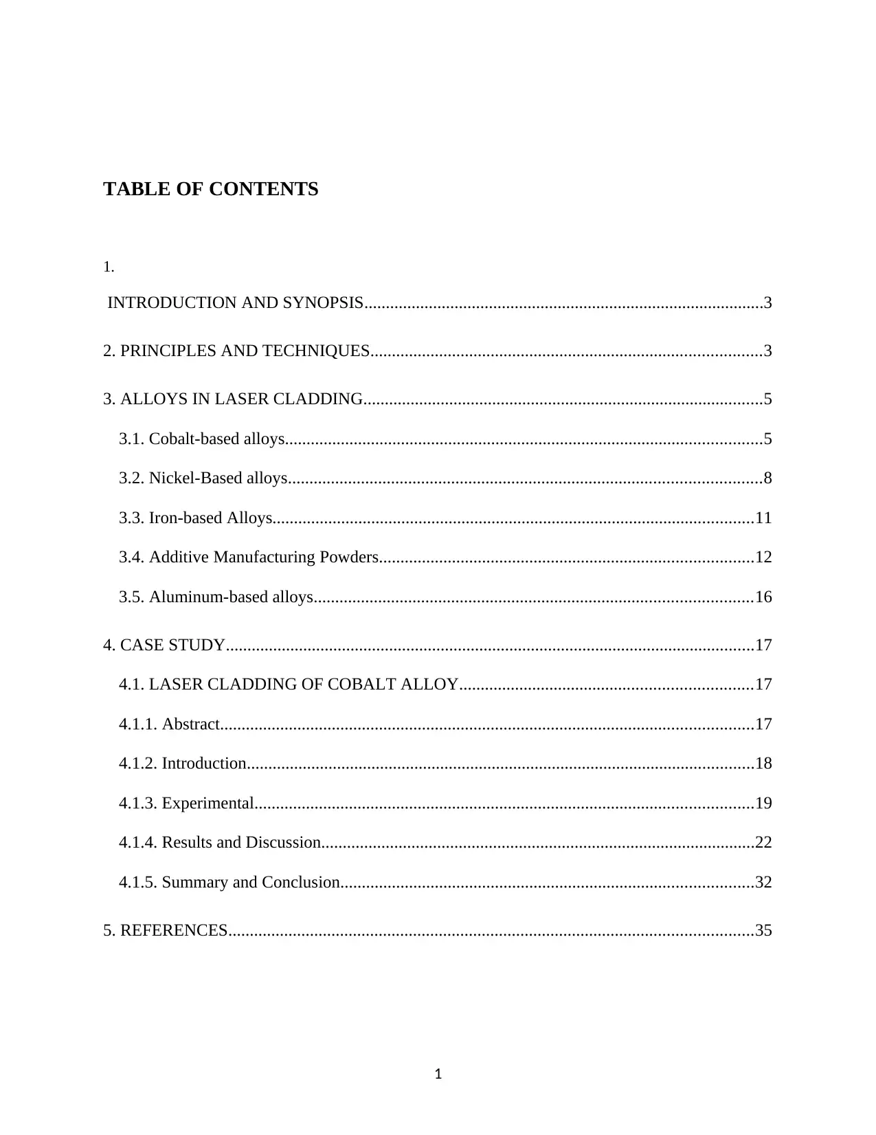
TABLE OF CONTENTS
1.
INTRODUCTION AND SYNOPSIS.............................................................................................3
2. PRINCIPLES AND TECHNIQUES...........................................................................................3
3. ALLOYS IN LASER CLADDING.............................................................................................5
3.1. Cobalt-based alloys...............................................................................................................5
3.2. Nickel-Based alloys..............................................................................................................8
3.3. Iron-based Alloys................................................................................................................11
3.4. Additive Manufacturing Powders.......................................................................................12
3.5. Aluminum-based alloys......................................................................................................16
4. CASE STUDY...........................................................................................................................17
4.1. LASER CLADDING OF COBALT ALLOY....................................................................17
4.1.1. Abstract............................................................................................................................17
4.1.2. Introduction......................................................................................................................18
4.1.3. Experimental....................................................................................................................19
4.1.4. Results and Discussion.....................................................................................................22
4.1.5. Summary and Conclusion................................................................................................32
5. REFERENCES..........................................................................................................................35
1
Secure Best Marks with AI Grader
Need help grading? Try our AI Grader for instant feedback on your assignments.
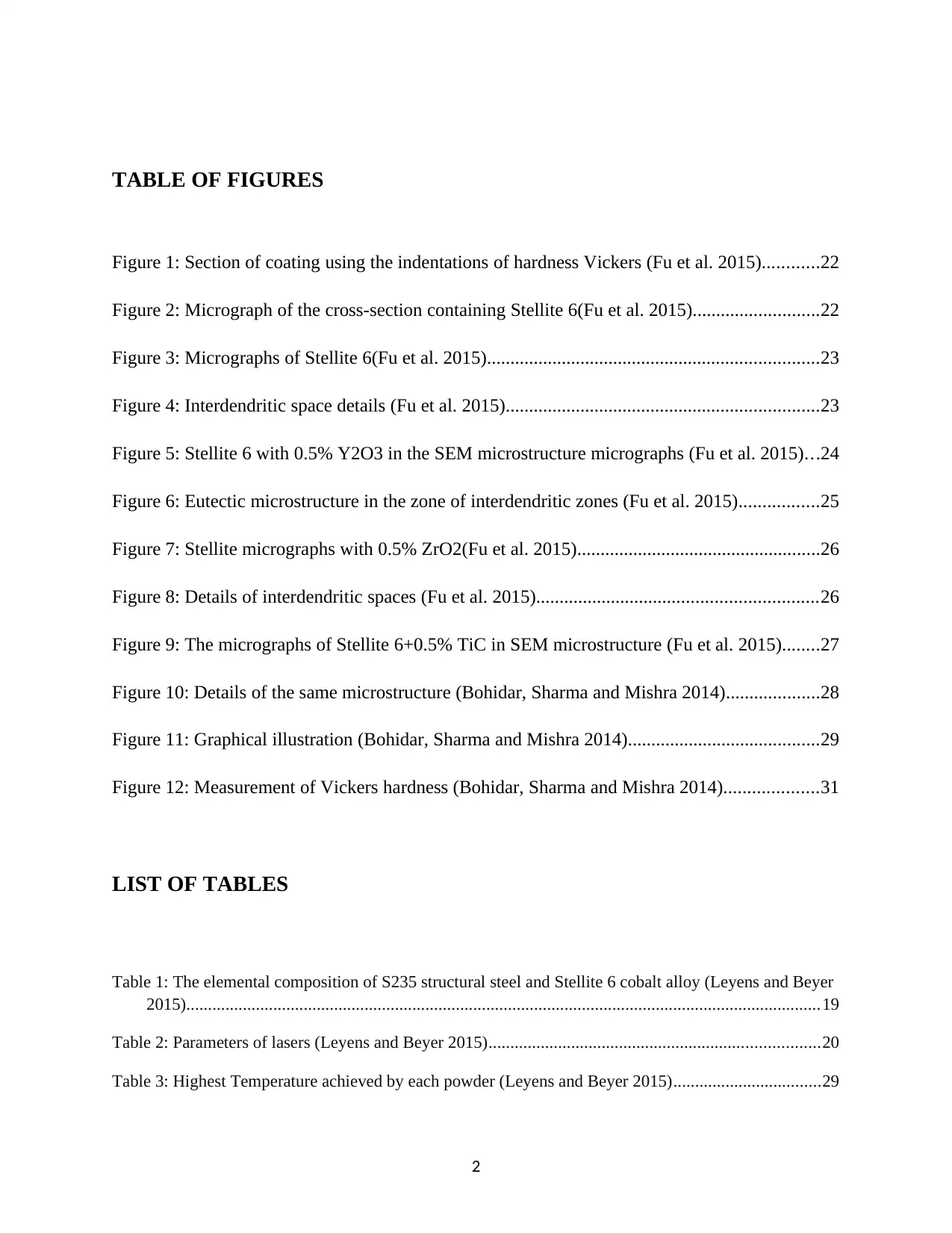
TABLE OF FIGURES
Figure 1: Section of coating using the indentations of hardness Vickers (Fu et al. 2015)............22
Figure 2: Micrograph of the cross-section containing Stellite 6(Fu et al. 2015)...........................22
Figure 3: Micrographs of Stellite 6(Fu et al. 2015).......................................................................23
Figure 4: Interdendritic space details (Fu et al. 2015)...................................................................23
Figure 5: Stellite 6 with 0.5% Y2O3 in the SEM microstructure micrographs (Fu et al. 2015)...24
Figure 6: Eutectic microstructure in the zone of interdendritic zones (Fu et al. 2015).................25
Figure 7: Stellite micrographs with 0.5% ZrO2(Fu et al. 2015)....................................................26
Figure 8: Details of interdendritic spaces (Fu et al. 2015)............................................................26
Figure 9: The micrographs of Stellite 6+0.5% TiC in SEM microstructure (Fu et al. 2015)........27
Figure 10: Details of the same microstructure (Bohidar, Sharma and Mishra 2014)....................28
Figure 11: Graphical illustration (Bohidar, Sharma and Mishra 2014).........................................29
Figure 12: Measurement of Vickers hardness (Bohidar, Sharma and Mishra 2014)....................31
LIST OF TABLES
Table 1: The elemental composition of S235 structural steel and Stellite 6 cobalt alloy (Leyens and Beyer
2015)..................................................................................................................................................19
Table 2: Parameters of lasers (Leyens and Beyer 2015)............................................................................20
Table 3: Highest Temperature achieved by each powder (Leyens and Beyer 2015)..................................29
2
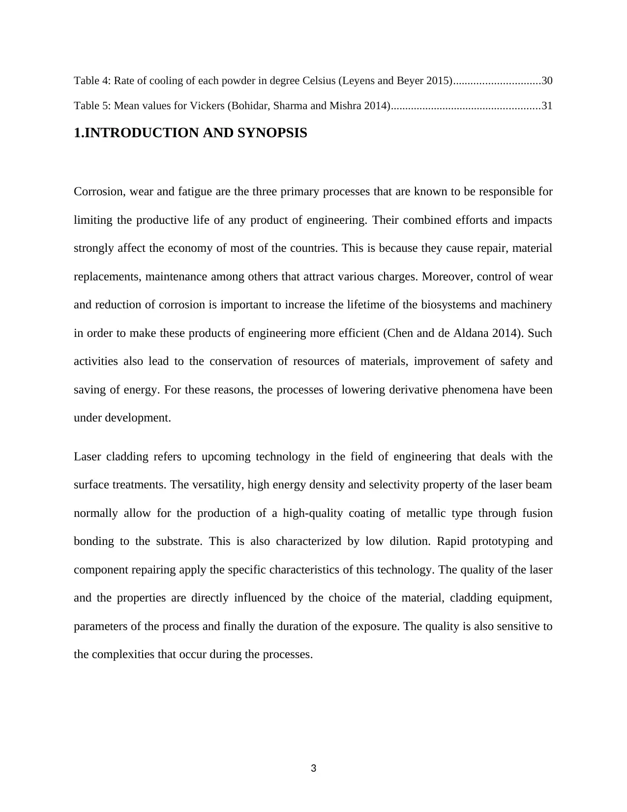
Table 4: Rate of cooling of each powder in degree Celsius (Leyens and Beyer 2015)..............................30
Table 5: Mean values for Vickers (Bohidar, Sharma and Mishra 2014)....................................................31
1.INTRODUCTION AND SYNOPSIS
Corrosion, wear and fatigue are the three primary processes that are known to be responsible for
limiting the productive life of any product of engineering. Their combined efforts and impacts
strongly affect the economy of most of the countries. This is because they cause repair, material
replacements, maintenance among others that attract various charges. Moreover, control of wear
and reduction of corrosion is important to increase the lifetime of the biosystems and machinery
in order to make these products of engineering more efficient (Chen and de Aldana 2014). Such
activities also lead to the conservation of resources of materials, improvement of safety and
saving of energy. For these reasons, the processes of lowering derivative phenomena have been
under development.
Laser cladding refers to upcoming technology in the field of engineering that deals with the
surface treatments. The versatility, high energy density and selectivity property of the laser beam
normally allow for the production of a high-quality coating of metallic type through fusion
bonding to the substrate. This is also characterized by low dilution. Rapid prototyping and
component repairing apply the specific characteristics of this technology. The quality of the laser
and the properties are directly influenced by the choice of the material, cladding equipment,
parameters of the process and finally the duration of the exposure. The quality is also sensitive to
the complexities that occur during the processes.
3
2.PRINCIPLES AND TECHNIQUES
The model definitions that can be used in the description of the entire exercise to predict the
properties of coatings, therefore, become very fundamental. Some of the materials that are used
in the laser cladding include alloys of various substances. Also, the process of dilution negatively
affects the warm oxidation conduct of the amalgam. The oxidation rate increments on expanding
dilution and disastrous oxidation have been seen in the most exceedingly terrible preparing
conditions, for example, elevated cladding and high temperature. Indeed, even with restricted
dilution at interfaces, the relative diminishing in the oxidation rate between the first as well as
the second stage essentially indicates the reduction of the oxidation conduct amid test samples.
An unmistakable relationship amongst microhardness and process of dilution is uncovered
likewise in the cladds created with the NiBSi combination. Once more, this conduct is brought
about by the microstructure of the composite. On expanding weakened interface, microstructure
advances in two distinctive ways. The microstructure turns out to be increasingly dendritic since
iron dilution changes the compound creation of the NiBSi amalgam. This is relied upon to move
a long way from eutectic focuses along these lines thereby promoting proeutectic fusion.
In addition, with the expansion in weakening process, eutectic morphology advances towards
the development of the γ-nickel-boride eutectic and a silicon-rich component to the detriment of
the nickel-boride and nickel-silicide eutectic, which will, in general, vanish for the case of this
alloy. At the point when an alloy of iron has utilized a role as a substrate, the NiBSi combination
demonstrates the equivalent microstructural change; in the expansion, on expanding weakening
interfaces and the effectiveness of the graphite layer is confirmed. The morphology of this
4
Secure Best Marks with AI Grader
Need help grading? Try our AI Grader for instant feedback on your assignments.
graphite appears to change from spheroidal to vermicular and then falls on a ratio of G/R, for
example on expanding weakening zones (Qiu and Liu 2013). In the coatings created with a
blend of either Stellite12 or Stellite 21 powder or tungsten carbides, carbides disintegration
happens amid laser cladding and affects the last properties of the coatings used. Disintegration is
to a great extent affected by the preparing conditions during the examination. Disintegration gets
higher with the expansion in the laser control and when the substrate is preheated, fundamentally
in view of the increment in temperature of the liquefy pool which improves disintegration
marvels. Synthetic structure of the Stellite base powder additionally impacts disintegration: a
lower substance of tungsten and carbon supports the disintegration of the tungsten carbides.
In the network where no tungsten and 0.25% of carbon are available, carbides disintegration
prompts an increment in the microhardness, which beats the reduction in the content, along these
lines prompting an increment in the hardness of the coating itself. On the inverse, framework
microhardness of the stellite rich in tungsten and carbon does not get any benefit by carbides
disintegration: as an outcome, the hardness of the coating somewhat diminishes because of the
reduction of the content (Zhou et al 2016).
3.ALLOYS IN LASER CLADDING
3.1. Cobalt-based alloys
Alloy 1
Type of powder: Alloy 1
Composition in Nominal class: W 12.0; Cr 31.0; Si 1.0; C 2.5 and Co Bal.
5
FST p/n: M-489.93 M-489.95.
The range of size: -125+45μ -150+45μ.
Applications and properties:
These are cobalt alloys that are made from the composition of a chemical similar to
stellite
It is considered to be the hardest of the known standard alloys from cobalt.
It can keep its hardness up to a standard of 725 degrees.
It is more sensitive to crack than other cobalt alloys.
It has a high content of carbide in the matrix of cobalt. This leads to excellent resistance
to abrasion and erosion of solid particles.
Alloy 6
Type of Powder: Alloy 6
Composition in Nominal class: W 5.0; Cr 28.0; Si 1.0; C 1.0 and Co Bal.
FST p/: M-489.93 M-489.95
The range of Size: -125+45μ -150+45μ
Applications and properties:
It is the most commonly used alloy that provides excellent resistance to various forms of
mechanical and chemical degradation over a big range of temperatures.
It has perfect resistance to cavitation and impact.
6
It is capable of keeping hardness up to 500 degrees.
Alloy 12
Type of powder: Alloy 12
Composition in Norm: 8.5; Cr 30.0; Si 1.5; C 1.5 and Co Bal.
FST p/n: M-481.93 M-481.95.
Range size: -125+45μ -150+45μ.
Applications
This is a cobalt-based alloy that has a similar chemical composition as stellite 12.
It has better resistance to erosion and corrosion than alloy 6.
It has better resistance to thermal shocks and impacts.
T-400
Type of powder: T-400
Composition in Nominal class: Mo 28.0; Cr 8.5; Si 2.5 and Co Bal.
FST p/n: M-494.93 M-494.95.
Range size: -125+45μ -150+45μ.
Applications
This is an alloy with a similar chemical composition as Tribaloy T-400.
7
Paraphrase This Document
Need a fresh take? Get an instant paraphrase of this document with our AI Paraphraser
It has high resistance to corrosion.
It has high resistance to oxidation at higher temperatures.
It has high resistance to galling with other metals as well as wear.
T-800
Type of powder: T-800
Composition in Nominal class: Mo 28.0; Cr 17.0; Si 3.0 and Co Bal.
FST p/n: M-499.93 M-499.95.
Range Size: -125+45μ -150+45μ.
Applications
This is an alloy of cobalt whose chemical compositions the same as that of Tribaloy T-
800.
It has high resistance to corrosion.
It has high resistance to the effects of the oxidation at relatively elevated temperatures.
It has high resistance to galling and war effects. This translates to hot hardness properties
3.2. Nickel-Based alloys
Powder type: Alloy 625.
Composition by Nominal class: Cr 21.5 Mo 9.0 Nb 3.5 Fe<1.5; Ni bal.
FST p/n: M-341.93 M-341.95.
8
Range size: -125+45μ -150+45μ.
Applications and properties
These are Nickel based alloys that have a similar chemical composition as Inconel 625.
It has excellent resistance to corrosion this suitable for wide range of use in
environmental work.
High resistance to corrosion of stress that causes cracks.
The resistance of alloy to temperatures of oxidation.
They are normally used in in the repair of other nickel-based unalloyed and alloy that are
underlying the internal streets.
Type of Powder: Alloy C-276.
Composition by Nominal class: Cr 16.0; Mo 15.5; W 4.0; Fe 3.0 ; Ni bal
FST p/n: M-341.93 M-341.95.
Range Size: -125+45μ -150+45μ.
Applications and properties:
This is basically an alloy of Nickel that is having properties the same as that of Hastelloy
C276.
It has perfect resistance to corrosion in mineral acids that are hot and contaminated.
It has high resistance to strong oxidizers and chlorine gases that may be wet.
9
It is also resistant to cracking and corrosion of crevice.
Type of Powder: NiCrSiB 40HRC.
Composition by Nominal class.: Cr 10.0; Fe 2.5; Si 3.1; B 2.1; C 0.4 and Ni Bal
FST p/n: M.772.93 M-772.95.
Range Size: -125+45μ -150+45μ.
Applications and properties:
NiCrBSi alloys have good resistance to wear and corrosion.
They are normally used in cases where higher machinability is required.
The range of hardness is actually 40 HRC which is normally considered sufficient.
Type of Powder: NiCrSiB 50HRC.
Composition by Nom.: Cr 12.5; Fe 3.8; Si 3.7; B 2.2; C 0.55; Ni Bal
FST p/n:M-776.93 M-776.95.
Range size: -125+45μ -150+45μ.
Applications and properties
It has perfect resistance to wear corrosion. The resistance to abrasion can be reduced by
the use of Tungsten Carbide.
10
Secure Best Marks with AI Grader
Need help grading? Try our AI Grader for instant feedback on your assignments.
Powder Type: NiCrSiBCuMo.
Composition by Nominal categories: Cr 16.5; Fe 3.0; Si 4.5; B 3.8; C 0.55; Cu 2.1; Mo 5.0; Ni
Bal
FST p/n: M-777.93 M-777.75.
Range Size: -125+45μ -150+45μ.
Applications and properties
The alloys of NiCrBSi are normally obtained through the addition of Cu and Mo.
It has a perfect corrosion resistance in the solution of alkaline and acidic.
They have perfect resistance to such media as compared to CU and Mo alone.
3.3. Iron-based Alloys
Type of powder: 316L
Nominal Composition: 17.0; Ni 12.0; Mo 2.5; Si<0.75; C<0.03; Fe Bal
FST p/n:M-684.93 M-684.95.
The range of size: -125+45μ -150+45μ.
Applications and typical properties:
It is resistant to corrosion up to a temperature of 400 degrees Celsius.
It allows for easy machining and possible mirror finishing.
11
Powder Type: 431.
FST p/n: M-687.93 M-687.95.
The range of size -125+45μ -150+45μ.
Applications and typical properties:
This is commonly referred to as Martensitic steel of nickel chromium.
It has better resistance than steel 410 or steel 403 which offers good resistance to
corrosion (Qiu and Liu 2013).
It has perfect wear resistant.
3.4. Additive Manufacturing Powders
1.Type of Powder: Fe-Based | 20HRC (316L).
Composition in terms of Nom: Cr 17.0; Mo 2.0; Ni 12.0; Mn 2.0; Si 0.75 and Fe Bal.
FST p/n: AM-613.33
Size of range: -53+20μ.
Applications and properties
UNS S31603 DIN 1.4404
Physical properties
12

Its average density: 8.0 when powder form.
The Melting point (°C): 1370 – 1400
It has a thermal conductivity of 16.2 W/mK
The thermal Coefficient of Expansion (°Cx10-6): 15.9.
Features/Description
This particular material has excellent corrosion and mechanical resistance properties
Its hardness value is high
It has a higher toughness and ductility
It has a high machinability value
It has a very high flowability
Its oxygen content is low with very little contaminants.
Suggested Areas for usage
It is used in the making of pumps, metallic filters and other structural parts of automotive as can
be seen in the general industries.
2.Type of Powder: Ni-Based
Composition: Fe 17.0; Ti 2.0; Si 1.0; Cr 22.0; Mo 8.0; W 1.0 and Bal. Ni
FST p/n: AM-330.33
Range size: -53+20μ.
Properties of UNS N06002 DIN 2.4665
Physical properties
13
Paraphrase This Document
Need a fresh take? Get an instant paraphrase of this document with our AI Paraphraser
Average density: 8.2 in the form of powder.
Hardness: 250 HV10.
Features/Description
This particular alloy has basic characteristics which include resistance to oxidation, high strength
at elevated temperatures which extend up to 1200 degrees. Its application can be in the areas
such as gas turbine parts and in the aerospace technology.
Suggested Uses
The components that have been built from this particular alloy can be treated by heat while
varying the material properties within a specified range to meet specific use. In all these
processes of heat treatments, the component can be machined, welded, spark eroded, polished,
micro shot-peened and finally coated as required.
3.Powder Type: Ni-Based (625).
Composition: Fe 5.0; Co 1.0; Cr 23.0; Mo 9.0; Nb 3.0
FST p/n: AM-331.33.
Range in Size: -53+20μ.
Applications and properties
UNS N06625 DIN 2.4856
Physical properties
• It has an average density of 8.44 when in the form of powder)
14
• The average melting point falls in the range (°C): 1290 – 1350
• The alloy has a thermal conductivity value of 12.8 10-6K-1
• The components thermal Coefficient of Expansion value is (°Cx10-6): 9-10.
Suggested Uses
This particular alloy is known for having characteristics such as creep, rupture strength, and very
high tensile strength.
The corrosion resistance of the material is equally high as reflected in the performance in most of
the environments that are considered to be corrosive like in the sea water. Such an environment
like sea water normally requires crevice and pitting value that is high. The other desirable
characteristics that are required by the environments include:
High resistance to creep
Very high oxidation and corrosion resistance at specific temperatures. These are a
temperature that is considered to be high.
Excellent welding
Nonmagnetic
Areas suggested for use
The addition of Mo and Nb normally give the alloy high toughness and very high strength in the
conditions that are considered to be for annealing. That is used in the areas in the areas that
require similar characteristics in the case of the defense and in the aerospace, Automotive and
15
other chemical processes in various industries. In the case of the oil and gas industry and marine
engineering at large, the application is quite perfecting some cases, the alloy-based materials
have been used in the making of seawater heat exchangers and other nuclear components.
3.5. Aluminum-based alloys
A380 Aluminium is normally used in laser cladding. Its powders are mixed with other
compounds in the ratio of Al: Ni: TiC = 3:1:0.5. The mixing exercise is normally carried out by
the use of ball milling a process that lasts for almost 13hours. This is followed by the connection
with PVA on the surface of the substrate as an agent of precondition. The powders thickness is
taken as 0.5mm. In some cases, a coarse-grained SiC powder (these are those particles between
0.5 and 40 mm) and a fine-grained SiC powder (50% of particles < 0.5 mm, 90% < 1.8 mm) are
used (Shah et al 2014).
During the process, the equipment that is used for laser cladding is called IPG-YLS-5000W
yttrium-doped multimode fiber laser. This particular gadget has a beam spot diameter of over
17mm. Argon vapor is used as the shielding gas at the flow rate of 20L/min. The mixing process
takes into account the proper parameters of the cladding. During the process of cladding, the
powder of Aluminium is vaporized thermally. The faster speed of scanning normally gives less
time for the vapor to escape which leads to a layer with bubbles.
Application
These alloys are used widely in automotive, aerospace and in power machinery. These
applications exploit the other properties of Aluminium which include good plasticity, low
density, and low cost.
16
Secure Best Marks with AI Grader
Need help grading? Try our AI Grader for instant feedback on your assignments.
4. CASE STUDY
4.1. LASER CLADDING OF COBALT ALLOY
4.1.1. Abstract
There is an urgent need in various industrial sectors including automotive, tooling and
aeronautics to improve the performance of the material surface under corrosion and wear
environments. Some of these conditions cannot be fulfilled by the use of conventional
modification measures of the surfaces as well as coating. This particular literature piece is a case
study of cobalt alloy coating by Nanocomposites through cladding process. These compounds
are normally obtained by melting down powder ion the surface of the steel. The powder is
normally obtained through milling of cobalt alloy mechanically into micro powder by the use of
titanium Nanopowder of carbide (Luo, Li and Li 2015). There is an establishment of a
comparison between conventional stellite laser cladded and the other stellite which has been
coated by the use of nanoparticles to establish their mechanical properties and microstructure.
The mechanical properties established include wearing resistance and hardness. There is
segregation of the particles of yttria into intergranular space while the particles of titanium
carbide are dispersed into the spaces of interdendritic and dendrite. The impact of similar
activities is the growth of equiaxial dendrites while using yttria which is finer as well. The
17
titanium nanoparticles mixed with carbides introduced an important reinforcement of the matrix
of cobalt alloy.
4.1.2. Introduction
There is normally need by various sectors of the industries to make improvements on the
performance of the surface of the materials that are always subjected to the condition of the tear,
wear, and corrosion. The requirements of such surfaces are normally complex and too strict to be
fulfilled by other conventional means of the treatment of the surfaces. Prior to the invention of
the technology of laser cladding, coating using painting used to be one of the most commonly
utilized techniques of the entire process. One of the best examples of cases where perfect surface
treatment I required is the use of steel. The tools of steel are normally subjected to very high
temperatures when they are used in the production of the dies, molds and other components; This
is common in almost all sectors of the industries. Such tools of steel normally provide high
resistance to corrosion and wear for both hot appliances and cold work.
The other alternative use of the steel could be incorporated in the low alloyed steels whose
surface characteristics can be improved through deposition of a layer of protection. The process
of the laser cladding can actually lead to the production of coating onto a particular workpiece. A
track of cladding is produced through injection of the particle of powder into the molten pool that
is produced but the moving beam of the laser. There is the provision of a very strong join by the
process of dilution between the substrate and coating (Leyens and Beyer 2015). In order to
effectively cover those areas that are larger than the diameter of the beam of lasers, deposition of
18
overlapping tracks. When the material of powder is actually presenting a poor behavior of the
flow, it can be replaced on the surface of the component. The powder that is injected can either
be a different material that is meant to improve the characteristics of the surface or the same
materials for reinforcement. This is the best examples of addition of nanoparticles to the powders
so as to obtain reinforced coatings of nanocomposites. In this particular paper, the focus is on the
study of approximation to produce alloy coatings of the alloy by the use of nanoparticles
coatings using laser cladding. This has been achieved by blowing of powder through the
injection nozzle instead of utilizing the concept of preplaced powder.
4.1.3. Experimental
The substrate that was used as a specimen was structural steel S235 which is actually low alloyed
steel. The mixtures of Co alloy powder (Stellite 6, 45-90 μm, Deloro) with 0.5% of three
different ceramic nanopowders (Y2O3, 30-50 nm; ZrO2, 50 nm; TiC, 20 nm; IoLiTec) were
applied as precursor materials to be applied as coatings on the steel surface. Mixing was
performed in a rotary ball mill Simoloyer CM01 (Zoz) to obtain an intimate mixture between the
ceramic and the alloy. Mixtures were carried out for 1200 s at 900 rpm.
Fe Co C Cr Si W Ni Mn Mo
S235 Bal. 0.17 1.49
Stellite 2.25 Bal 1.15 31.0 1.38 4.50 2.39 0.48 0.25
Table 1: The elemental composition of S235 structural steel as well as Stellite 6 cobalt alloy (Leyens and Beyer 2015)
The experiments were carried out by the use of LDL 160-3300 direct diode laser. This was
treated as the laser line. The power voltage that was applied was 3.3kW treated as maximum.
The mounting of the laser was on a 6 axes robot system of IRB4400 commonly known as ABB.
19
Paraphrase This Document
Need a fresh take? Get an instant paraphrase of this document with our AI Paraphraser
The delivered beam which was in the square shape was focused on a spot of size 3x3 square
millimeters on the same workpiece. The blended mixture of ceramic nanoparticles and Stellite 6
were all introduced into a feeder that was obtained from a reliable manufacturer. The
transportation of the powder was done by the means of argon stream to the powder coaxial
nozzle marked as COAX 8. This was then blown on the substrate by the laser beam at the same
incident point (Li et al 2015).
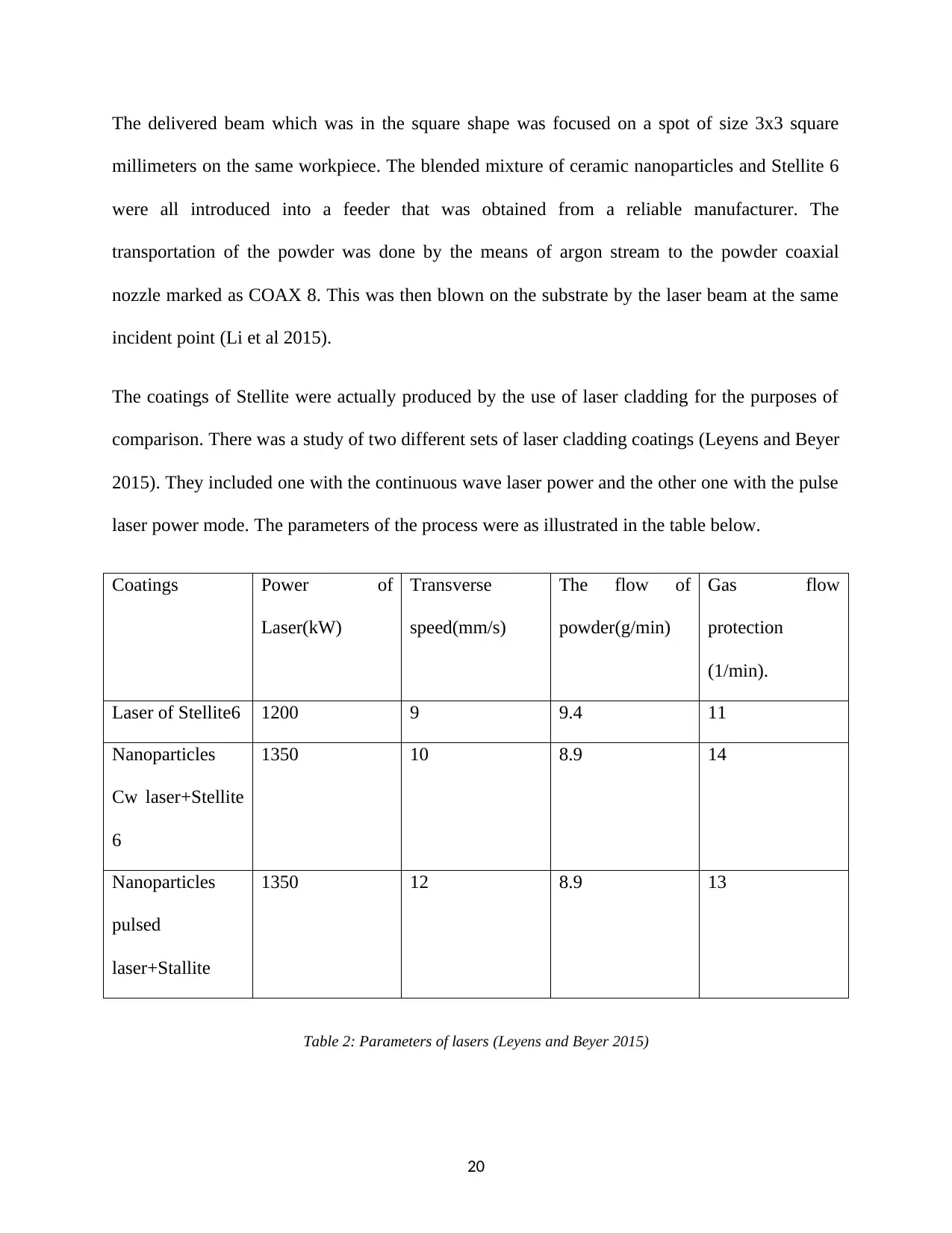
The coatings of Stellite were actually produced by the use of laser cladding for the purposes of
comparison. There was a study of two different sets of laser cladding coatings (Leyens and Beyer
2015). They included one with the continuous wave laser power and the other one with the pulse
laser power mode. The parameters of the process were as illustrated in the table below.
Coatings Power of
Laser(kW)
Transverse
speed(mm/s)
The flow of
powder(g/min)
Gas flow
protection
(1/min).
Laser of Stellite6 1200 9 9.4 11
Nanoparticles
Cw laser+Stellite
6
1350 10 8.9 14
Nanoparticles
pulsed
laser+Stallite
1350 12 8.9 13
Table 2: Parameters of lasers (Leyens and Beyer 2015)
20
During the processing by the use of a laser, the maximum temperature on the melted pool surface
was measured by the use of pyrometer of one –wavelength which was placed confocal with the
beam of the laser. The recording of the process was done by the use of thermal detection tool
within the camera of thermographic (Weng, Chen and Yu 2014). The videos that were obtained
were post-processed and later analyzed to get the cooling curves during the process of coating
cooling or solidification. In all the two cases the value was maintained at 0.18 for the emissivity
of Stellite 6. By the use of this specific value of emissivity and the optics of the camera, the
range of detection for the camera was between the thermographic value of 680 and 1970 degrees
Celsius. This kind of limitation was the reason behind the use of pyrometer that has a wider
range of measurement. This allowed for the measurements of maximum temperature.
Metallographic techniques were used in the measurements of microstructural characterization.
There was the use of an Olympus metallographic optical microscope (OM) and Hitachi FE4500
Field Emission Scanning Electron Microscope (FEGSEM). The analysis of the composition of
various observed phases was done by the use of an energy dispersive X-ray spectroscopy (EDS)
attached to SEM as microprobe. There was cutting of the cross sections samples and subsequent
polishing to match mirror finish by the use of abrasive paper. The last stage involved diamond
finishing or polishing. Kalling solution was then used in the etching process. This was very
crucial in revealing the microstructure under the OM.
Assessment of the mechanical behavior of the new surfaces was done in terms of microhardness.
The measurement of microhardness was done by the use of Emcotest M1C 010 as the tester of
automatic digital microhardness. A Vicker indenter under the test load of 15 s dwell time and the
50kg load was applied. The procedures for the measurements have been illustrated in the figure
below. The horizontal measurement was done to obtain the mean value for coating hardness. The
21
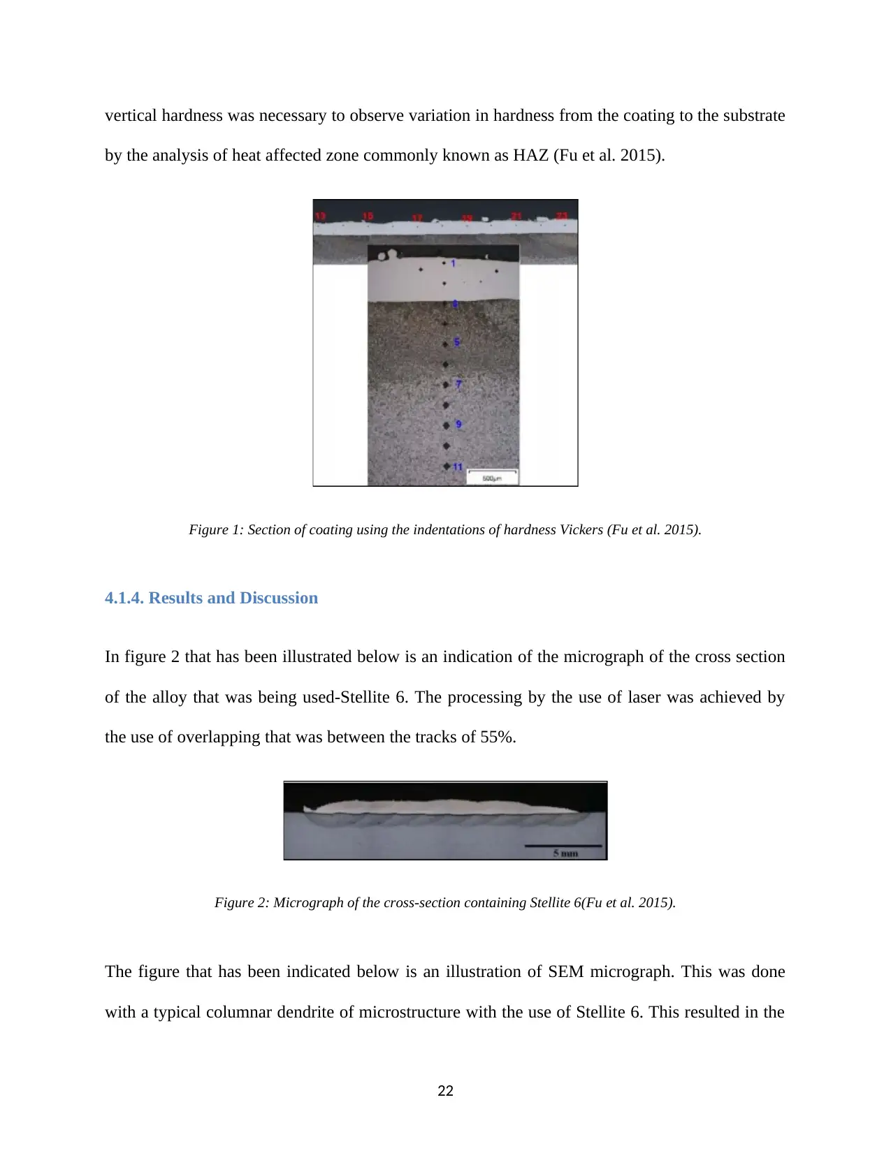
vertical hardness was necessary to observe variation in hardness from the coating to the substrate
by the analysis of heat affected zone commonly known as HAZ (Fu et al. 2015).
Figure 1: Section of coating using the indentations of hardness Vickers (Fu et al. 2015).
4.1.4. Results and Discussion
In figure 2 that has been illustrated below is an indication of the micrograph of the cross section
of the alloy that was being used-Stellite 6. The processing by the use of laser was achieved by
the use of overlapping that was between the tracks of 55%.
Figure 2: Micrograph of the cross-section containing Stellite 6(Fu et al. 2015).
The figure that has been indicated below is an illustration of SEM micrograph. This was done
with a typical columnar dendrite of microstructure with the use of Stellite 6. This resulted in the
22
Secure Best Marks with AI Grader
Need help grading? Try our AI Grader for instant feedback on your assignments.
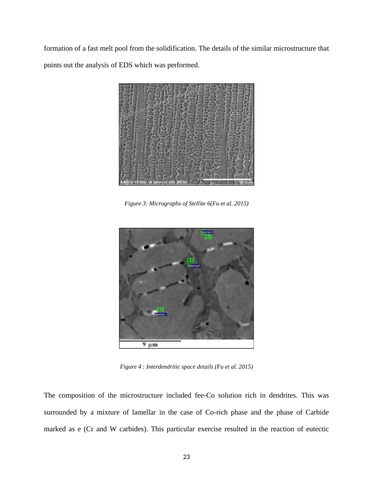
formation of a fast melt pool from the solidification. The details of the similar microstructure that
points out the analysis of EDS which was performed.
Figure 3: Micrographs of Stellite 6(Fu et al. 2015)
Figure 4 : Interdendritic space details (Fu et al. 2015)
The composition of the microstructure included fee-Co solution rich in dendrites. This was
surrounded by a mixture of lamellar in the case of Co-rich phase and the phase of Carbide
marked as e (Cr and W carbides). This particular exercise resulted in the reaction of eutectic
23
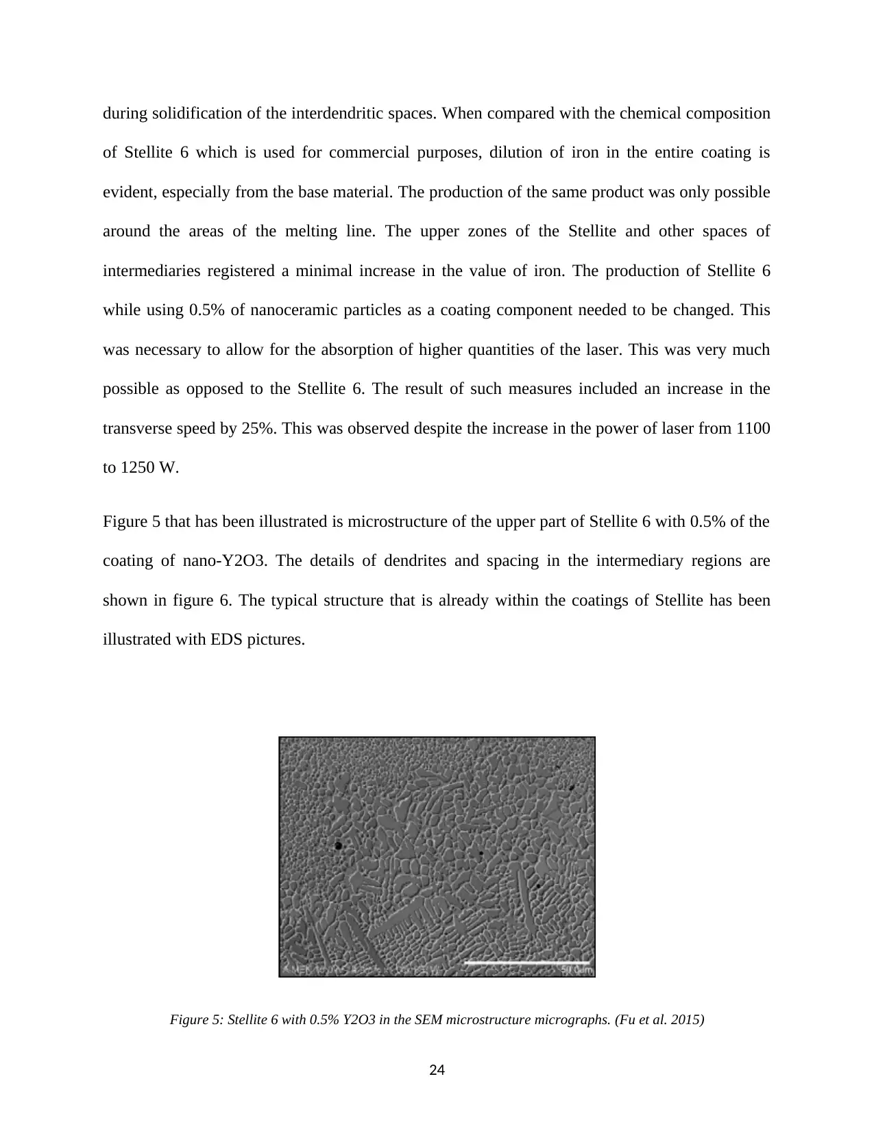
during solidification of the interdendritic spaces. When compared with the chemical composition
of Stellite 6 which is used for commercial purposes, dilution of iron in the entire coating is
evident, especially from the base material. The production of the same product was only possible
around the areas of the melting line. The upper zones of the Stellite and other spaces of
intermediaries registered a minimal increase in the value of iron. The production of Stellite 6
while using 0.5% of nanoceramic particles as a coating component needed to be changed. This
was necessary to allow for the absorption of higher quantities of the laser. This was very much
possible as opposed to the Stellite 6. The result of such measures included an increase in the
transverse speed by 25%. This was observed despite the increase in the power of laser from 1100
to 1250 W.
Figure 5 that has been illustrated is microstructure of the upper part of Stellite 6 with 0.5% of the
coating of nano-Y2O3. The details of dendrites and spacing in the intermediary regions are
shown in figure 6. The typical structure that is already within the coatings of Stellite has been
illustrated with EDS pictures.
Figure 5: Stellite 6 with 0.5% Y2O3 in the SEM microstructure micrographs. (Fu et al. 2015)
24
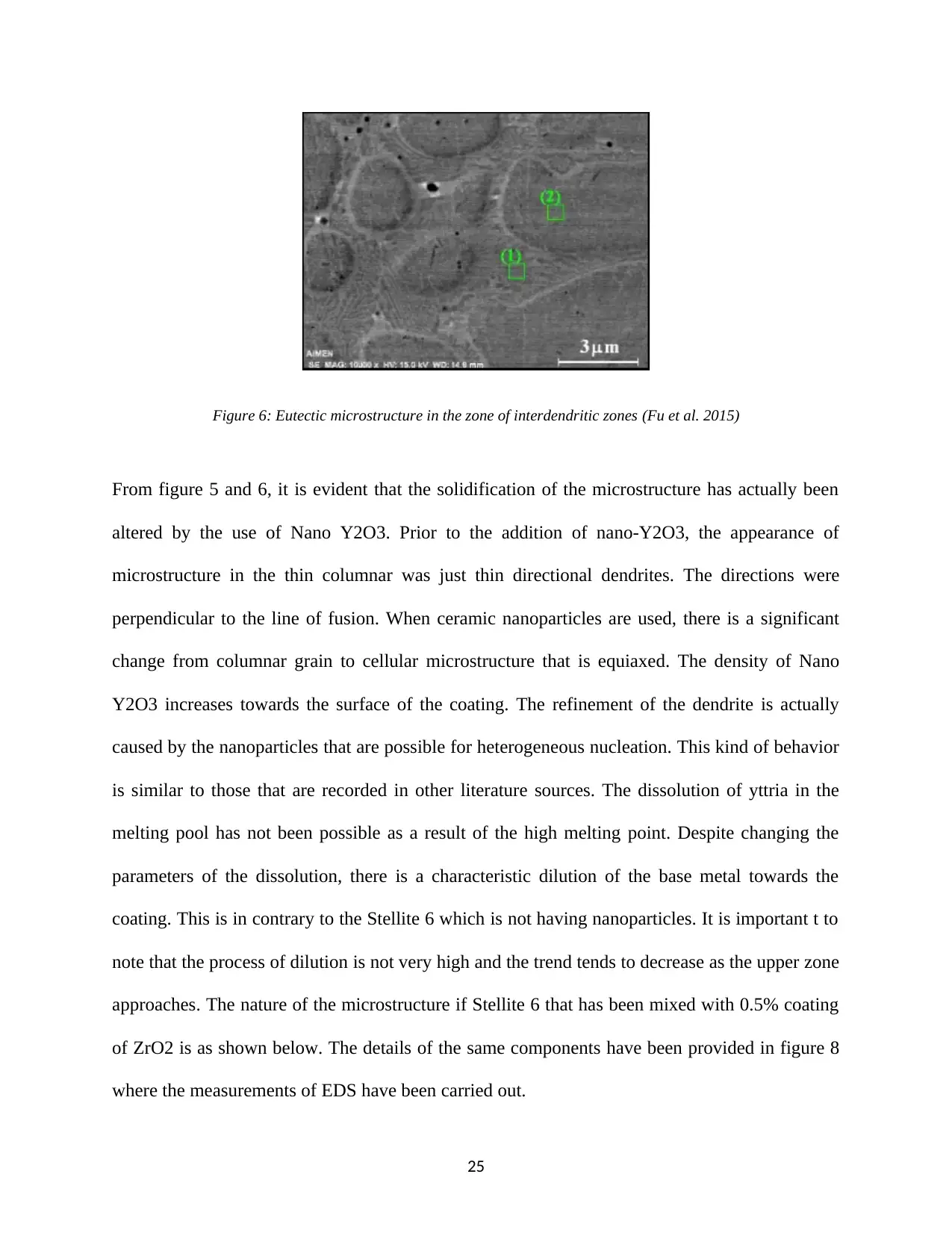
Figure 6: Eutectic microstructure in the zone of interdendritic zones (Fu et al. 2015)
From figure 5 and 6, it is evident that the solidification of the microstructure has actually been
altered by the use of Nano Y2O3. Prior to the addition of nano-Y2O3, the appearance of
microstructure in the thin columnar was just thin directional dendrites. The directions were
perpendicular to the line of fusion. When ceramic nanoparticles are used, there is a significant
change from columnar grain to cellular microstructure that is equiaxed. The density of Nano
Y2O3 increases towards the surface of the coating. The refinement of the dendrite is actually
caused by the nanoparticles that are possible for heterogeneous nucleation. This kind of behavior
is similar to those that are recorded in other literature sources. The dissolution of yttria in the
melting pool has not been possible as a result of the high melting point. Despite changing the
parameters of the dissolution, there is a characteristic dilution of the base metal towards the
coating. This is in contrary to the Stellite 6 which is not having nanoparticles. It is important t to
note that the process of dilution is not very high and the trend tends to decrease as the upper zone
approaches. The nature of the microstructure if Stellite 6 that has been mixed with 0.5% coating
of ZrO2 is as shown below. The details of the same components have been provided in figure 8
where the measurements of EDS have been carried out.
25
Paraphrase This Document
Need a fresh take? Get an instant paraphrase of this document with our AI Paraphraser
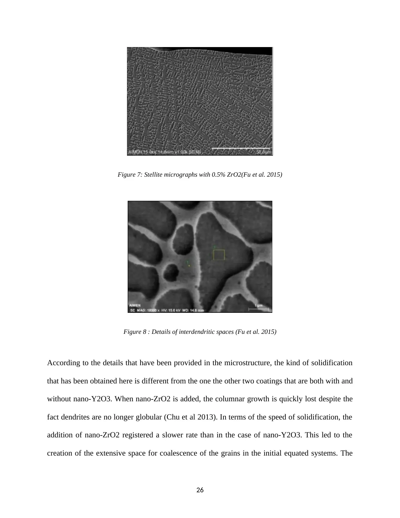
Figure 7: Stellite micrographs with 0.5% ZrO2(Fu et al. 2015)
Figure 8 : Details of interdendritic spaces (Fu et al. 2015)
According to the details that have been provided in the microstructure, the kind of solidification
that has been obtained here is different from the one the other two coatings that are both with and
without nano-Y2O3. When nano-ZrO2 is added, the columnar growth is quickly lost despite the
fact dendrites are no longer globular (Chu et al 2013). In terms of the speed of solidification, the
addition of nano-ZrO2 registered a slower rate than in the case of nano-Y2O3. This led to the
creation of the extensive space for coalescence of the grains in the initial equated systems. The
26
particles of ceramic nano-ZrO2 p did not melt considering that their melting points are very high.
Also, they are segregated to the spaces of interdendritic leading to the provision of the spaces for
refinement. The dilution of the component of iron that originated from the metal base of nano-
ZrO2 coating also registered higher values almost twice as compared to particles of nano-Y2O3.
This is a clear indication that there was a higher input of heat during the preparation and
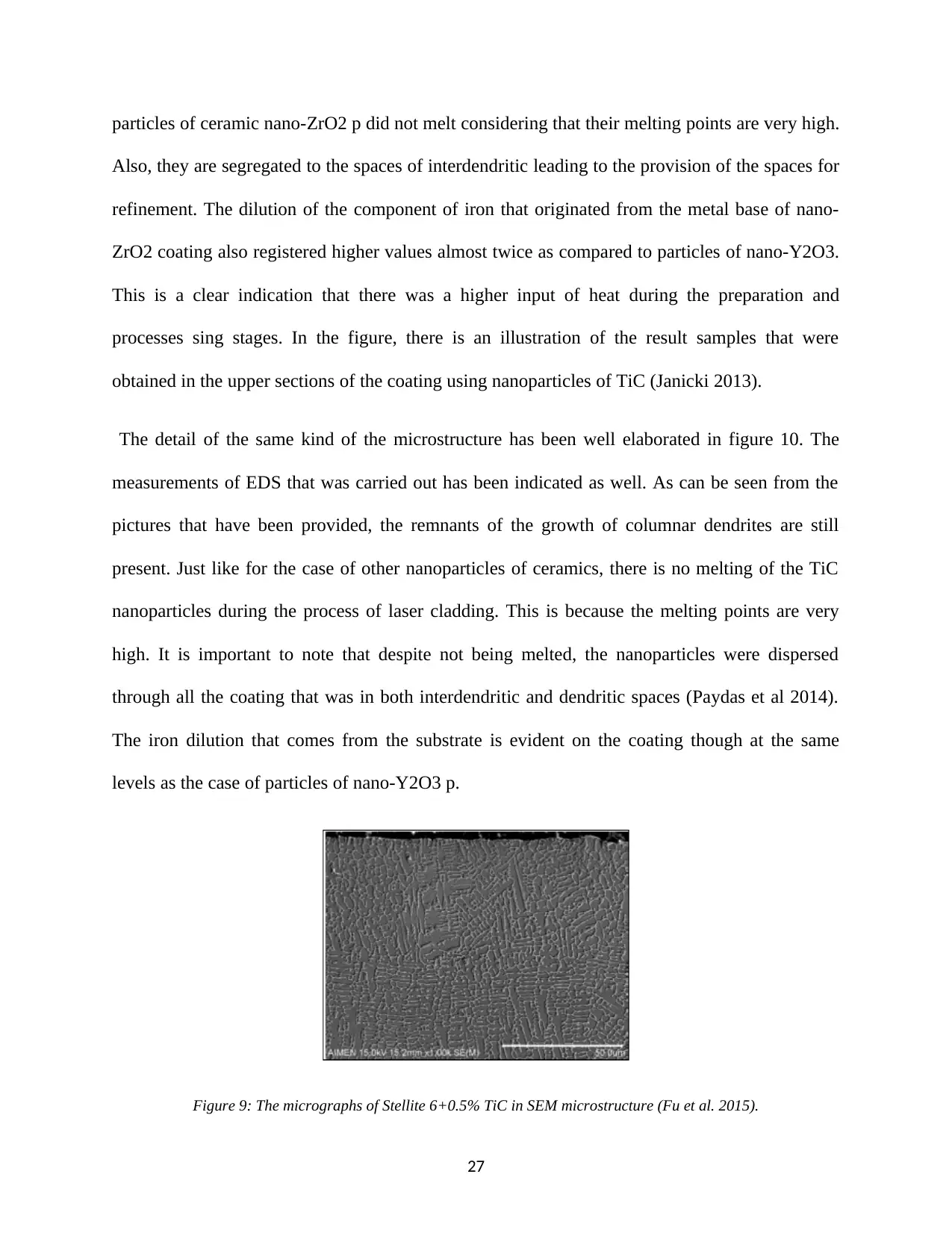
processes sing stages. In the figure, there is an illustration of the result samples that were
obtained in the upper sections of the coating using nanoparticles of TiC (Janicki 2013).
The detail of the same kind of the microstructure has been well elaborated in figure 10. The
measurements of EDS that was carried out has been indicated as well. As can be seen from the
pictures that have been provided, the remnants of the growth of columnar dendrites are still
present. Just like for the case of other nanoparticles of ceramics, there is no melting of the TiC
nanoparticles during the process of laser cladding. This is because the melting points are very
high. It is important to note that despite not being melted, the nanoparticles were dispersed
through all the coating that was in both interdendritic and dendritic spaces (Paydas et al 2014).
The iron dilution that comes from the substrate is evident on the coating though at the same
levels as the case of particles of nano-Y2O3 p.
Figure 9: The micrographs of Stellite 6+0.5% TiC in SEM microstructure (Fu et al. 2015).
27
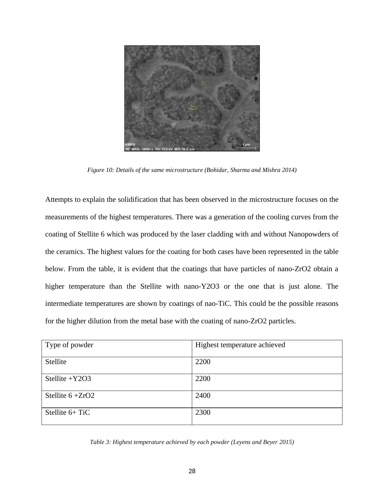
Figure 10: Details of the same microstructure (Bohidar, Sharma and Mishra 2014)
Attempts to explain the solidification that has been observed in the microstructure focuses on the
measurements of the highest temperatures. There was a generation of the cooling curves from the
coating of Stellite 6 which was produced by the laser cladding with and without Nanopowders of
the ceramics. The highest values for the coating for both cases have been represented in the table
below. From the table, it is evident that the coatings that have particles of nano-ZrO2 obtain a
higher temperature than the Stellite with nano-Y2O3 or the one that is just alone. The
intermediate temperatures are shown by coatings of nao-TiC. This could be the possible reasons
for the higher dilution from the metal base with the coating of nano-ZrO2 particles.
Type of powder Highest temperature achieved
Stellite 2200
Stellite +Y2O3 2200
Stellite 6 +ZrO2 2400
Stellite 6+ TiC 2300
Table 3: Highest temperature achieved by each powder (Leyens and Beyer 2015)
28
Secure Best Marks with AI Grader
Need help grading? Try our AI Grader for instant feedback on your assignments.
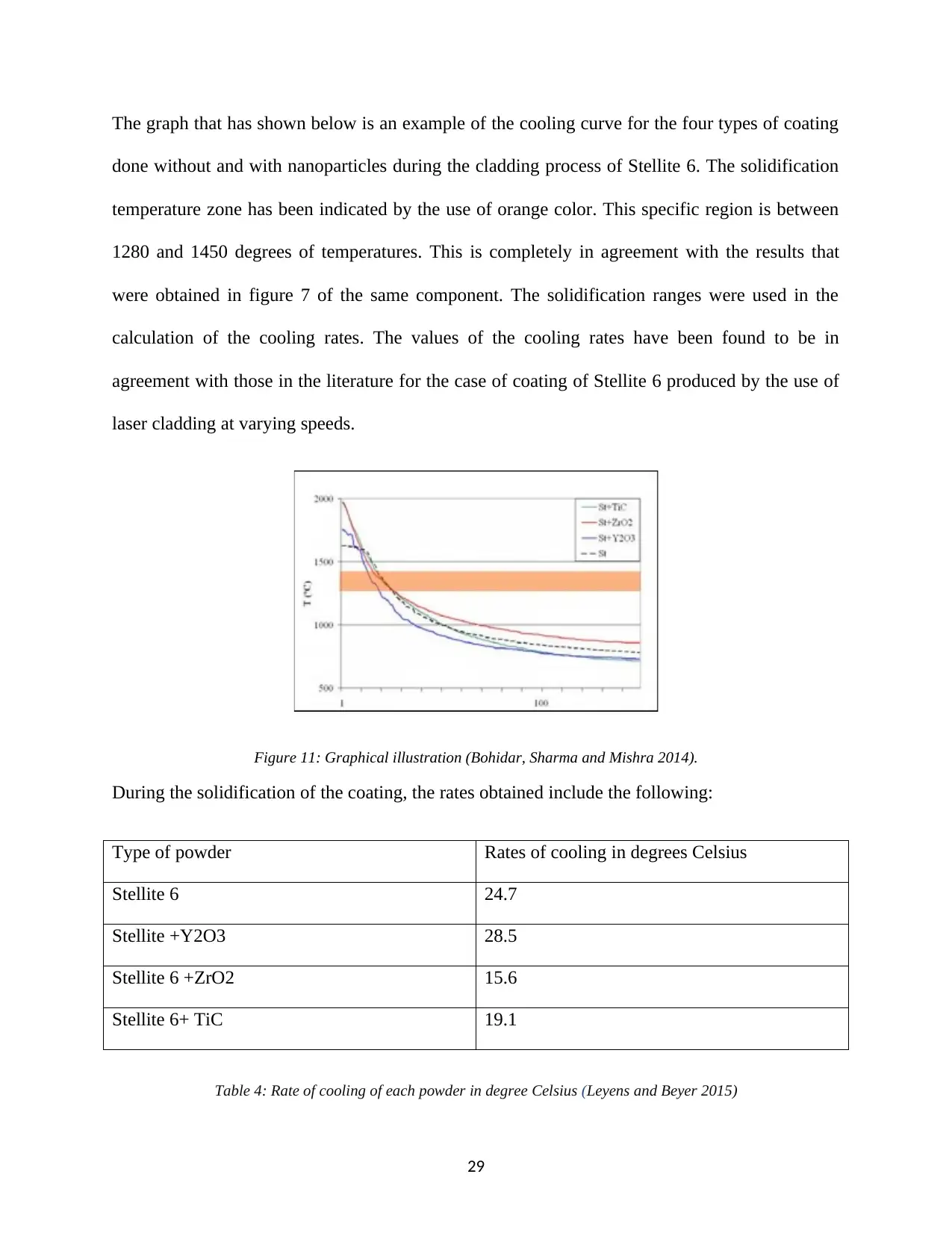
The graph that has shown below is an example of the cooling curve for the four types of coating
done without and with nanoparticles during the cladding process of Stellite 6. The solidification
temperature zone has been indicated by the use of orange color. This specific region is between
1280 and 1450 degrees of temperatures. This is completely in agreement with the results that
were obtained in figure 7 of the same component. The solidification ranges were used in the
calculation of the cooling rates. The values of the cooling rates have been found to be in
agreement with those in the literature for the case of coating of Stellite 6 produced by the use of
laser cladding at varying speeds.
Figure 11: Graphical illustration (Bohidar, Sharma and Mishra 2014).
During the solidification of the coating, the rates obtained include the following:
Type of powder Rates of cooling in degrees Celsius
Stellite 6 24.7
Stellite +Y2O3 28.5
Stellite 6 +ZrO2 15.6
Stellite 6+ TiC 19.1
Table 4: Rate of cooling of each powder in degree Celsius (Leyens and Beyer 2015)
29
The rate of cooling of coating that had nano-Y2O3 was found to be almost twice that which had
nano-ZrO2. The dendritic growth has been limited by the faster solidification alongside
coalescence. This lead to the creation of equiaxed dendrites that was located close to the surface.
The higher times of solidification and maximum temperatures would lead to the growth of
dendrites as well as coalescence when particles of nano-ZrO2 are added. These kinds of results
are obtained due to the fact that Zircon has lower thermal conductivity than yttria. The
solidification that has been shown in the microstructure is intermediate between those coatings
with nano-ZrO2 and nano-Y2O3. This is because the coating that had nano-TiC particles was of
average values.
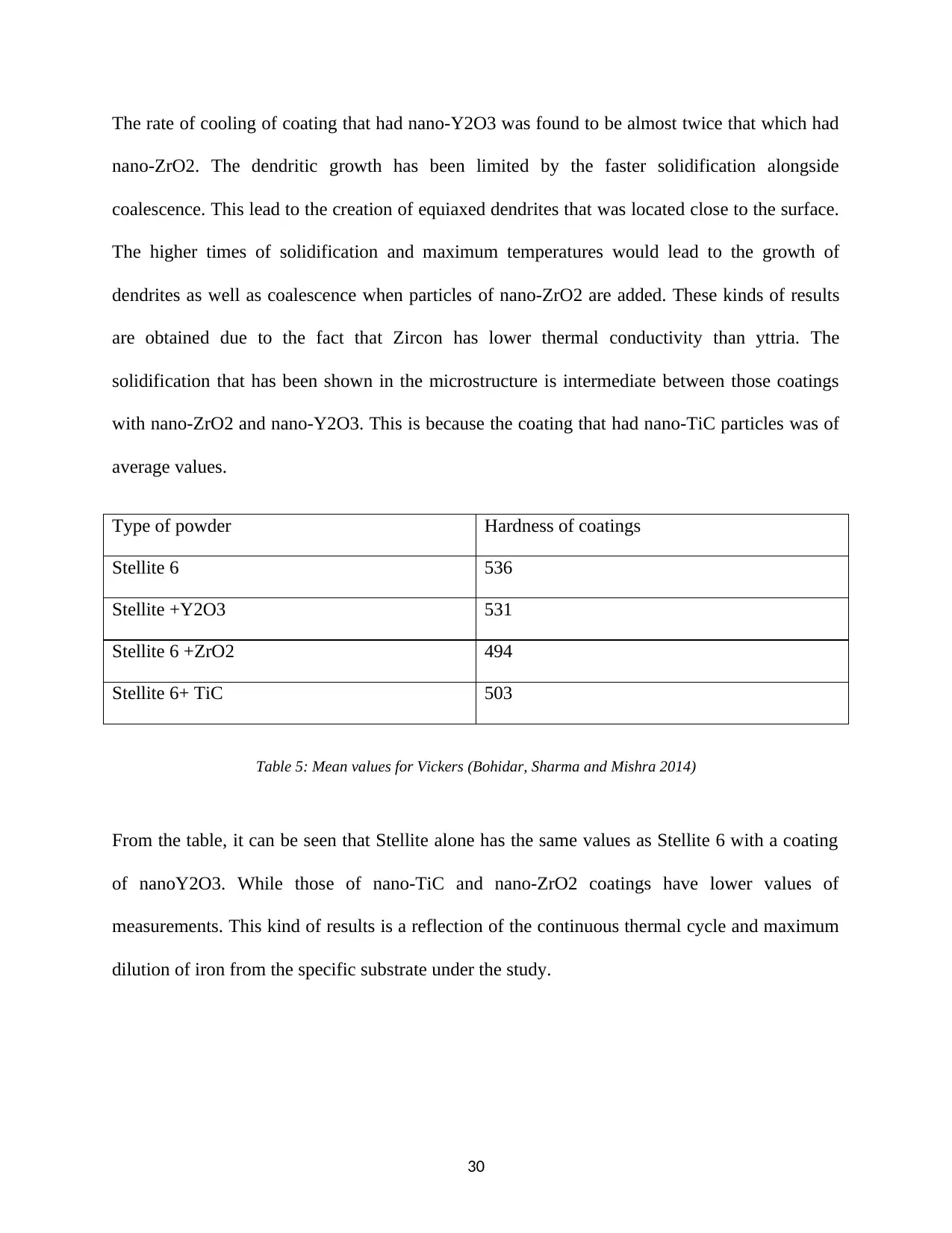
Type of powder Hardness of coatings
Stellite 6 536
Stellite +Y2O3 531
Stellite 6 +ZrO2 494
Stellite 6+ TiC 503
Table 5: Mean values for Vickers (Bohidar, Sharma and Mishra 2014)
From the table, it can be seen that Stellite alone has the same values as Stellite 6 with a coating
of nanoY2O3. While those of nano-TiC and nano-ZrO2 coatings have lower values of
measurements. This kind of results is a reflection of the continuous thermal cycle and maximum
dilution of iron from the specific substrate under the study.
30
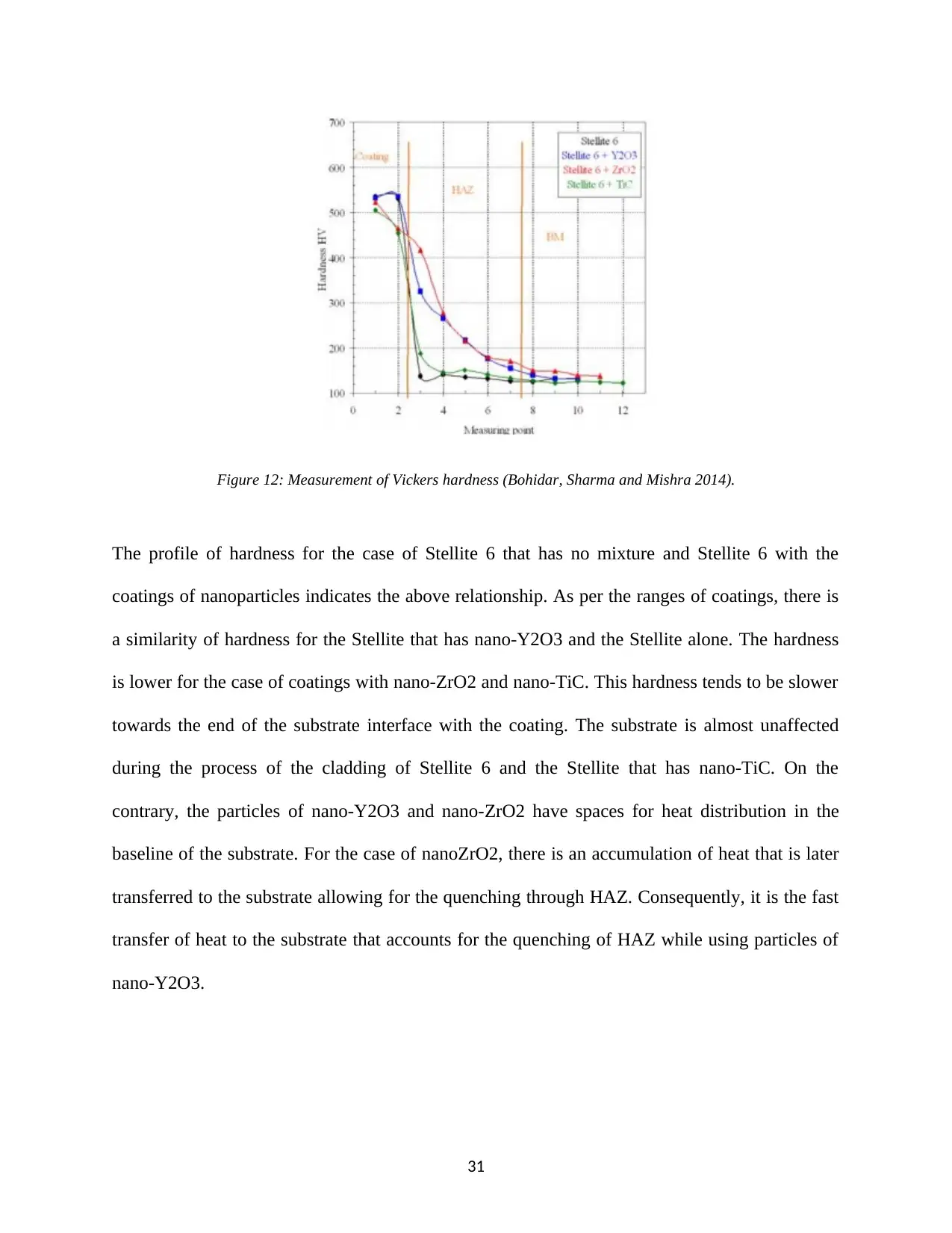
Figure 12: Measurement of Vickers hardness (Bohidar, Sharma and Mishra 2014).
The profile of hardness for the case of Stellite 6 that has no mixture and Stellite 6 with the
coatings of nanoparticles indicates the above relationship. As per the ranges of coatings, there is
a similarity of hardness for the Stellite that has nano-Y2O3 and the Stellite alone. The hardness
is lower for the case of coatings with nano-ZrO2 and nano-TiC. This hardness tends to be slower
towards the end of the substrate interface with the coating. The substrate is almost unaffected
during the process of the cladding of Stellite 6 and the Stellite that has nano-TiC. On the
contrary, the particles of nano-Y2O3 and nano-ZrO2 have spaces for heat distribution in the
baseline of the substrate. For the case of nanoZrO2, there is an accumulation of heat that is later
transferred to the substrate allowing for the quenching through HAZ. Consequently, it is the fast
transfer of heat to the substrate that accounts for the quenching of HAZ while using particles of
nano-Y2O3.
31
Paraphrase This Document
Need a fresh take? Get an instant paraphrase of this document with our AI Paraphraser
4.1.5. Summary and Conclusion
From this particular case study on the coatings of Stellite 6 that has nanoparticles of ceramics
and has been produced by laser cladding, the following conclusion can be drawn:
The addition of ceramic nanoparticles to Stellite 6 results into the refinement of the
dendrites which later promotes uniform nucleation. The microstructure changes
significantly from the grain columnar to cellular microstructure via the equiaxed state.
Those dendrites that have nanoparticles become denser and thinner (Weng et al 2013).
Despite the fact that refinement of the microstructure is obtained with three types of
particles of ceramics including (Y2O3, TiC, and ZrO2, the effects are only evident with
nano-Y2O3 as a result of its higher rates of cooling during the process of solidification.
There is no dissolution of the nanoparticles in the melt pool. They are being segregated to
interdendritic regions for the case of ZrO2 and Y2O3. However, for the case of TiC, it is
the dispersal that takes place.
The hardness of those coatings that contain nano-Y2O3 is the same that of Stellite 6
alone. The hardness is slightly lower for the case of coatings with nanoparticles of ZrO2
and TiC as a result of iron dilution which originates from the substrate of steel.
The major physical phenomenon that is usually involved in the process of laser cladding has
actually been evaluated and analyzed qualitatively (Bohidar, Sharma and Mishra 2014). The
parameters for the cladding including the materials for the cladding process have been discussed
effectively. There had been the performance of the properties of coating testing done as well.
The geometry of the clad relies upon the fundamental handling parameters and on the cladding
material, and models to gauge clad size and width have been obtained. Clad stature has a mind-
32
boggling connection with the developing cross-sectional zone of the clad: it is emphatically
affected by the bolstering rate, the checking speed, the material thickness and, somewhat, by the
laser control through the material productivity.
Then again, clad width is associated with the laser control and the examining speed. Through
these models, clad viewpoint proportion can be assessed with a decent estimate in the range
somewhere in the range of 5 and 20, inside which normal laser cladding coatings are delivered.
The explanatory relationship between preparing parameters and weakening characteristics has
been gotten (Chen et al 2013). Dilution is for the most part affected by the laser control and the
sustaining rate, while the impact of output speed is less articulated. In explicit, an increase in
dilution with the expansion in the laser control and the output speed alongside the reduction in
the rate of surface growth improves the quality of the product. These parameters are in great
concurrence with the aftereffects of the lively parity, where the reliance of dilution on the vitality
and powder accessible by the framework is affirmed. As illustrated, the representation of dilution
can be done by the vitality balancing between the powder and the substrate.
The impacts on the models of geometry and weakening of substrate material and preheating have
been talked about. Substrate preheating can be seen as an excess of vitality given to the cladding
framework, and it tends to be hence illustrated by an expanded laser control. In the particular
handling conditions used, substrate preheating of 400°C outcomes to be proportional to an
expansion in the laser intensity of 0.67 kW. Substrate material, on the inverse, does not alter the
clad geometry; however, it intensely influences the process of dilution (Baldridge et al 2013). In
particular, the thermophysical properties of the substrate impact the vitality parceling between
powder and substrate and, as expressed previously, they, therefore, influence the entire dilution.
33
The examination on the redistribution of energy in the laser cladding process affirmed the low
vigorous proficiency of the procedure, which is, for the most part, occurs because of the high
reflectivity of the fluid metal. No critical varieties have been seen because of the powder
materials. The point of rate, communicated through the cladding and dissolve pool geometry, has
been recognized as a helpful parameter to depict the parceling of energy during the procedure.
By fluctuating the edge of frequency, the consumed energy by the powder/substrate framework
does not change, however, the lively circulation of the process is radically changed. For low
points of occurrence slenderer clads with high weakening are created, and the majority of the
ingested heat is lost by conduction through the substrate. On expanding the edge of occurrence,
thicker clads are delivered with the beneficial outcomes of both lower results of dilution and
higher enthusiastic productivity.
The dilution influence may effectively affect the properties of the coatings. The occurrence of
dilution in the cladds created with the Stellite 6 powder prompts a decline in hardness and
microhardness, which is brought about by the microstructural development of the Co-based
combination (Abioye, McCartney and Clare 2015). On expanding the range of dilution, the cell
to dendritic change is proved. This change is clarified by the reduction of the grain to roundness
(G/R) proportion and the distinctive concoction arrangement. As far as possible the development
of the eutectic constituent inside carbides are limited, and therefore prompts the decline in the
hardness of the coating. In the clads created with Inconel 625 powder on the basis of expanding
dilution, microstructural development is proving together with the diminishing in clad
microhardness. In cladds with constrained effects of dilution, the dendritic structure is available
with interdendritic districts demonstrating the arrangement of niobium carbides with blocky
morphology
34
Secure Best Marks with AI Grader
Need help grading? Try our AI Grader for instant feedback on your assignments.
5. REFERENCES
Abioye, T.E., McCartney, D.G. and Clare, A.T., 2015. Laser cladding of Inconel 625 wire for
corrosion protection. Journal of Materials Processing Technology, 217, pp.232-240.
Baldridge, T., Poling, G., Foroozmehr, E., Kovacevic, R., Metz, T., Kadekar, V. and Gupta,
M.C., 2013. Laser cladding of Inconel 690 on Inconel 600 superalloy for corrosion protection in
nuclear applications. Optics and Lasers in Engineering, 51(2), pp.180-184.
Bohidar, S.K., Sharma, R. and Mishra, P.R., 2014. Functionally graded materials: A critical
review. International Journal of Research, 1(4), pp.289-301.
Chen, F. and de Aldana, J.V., 2014. Optical waveguides in crystalline dielectric materials
produced by femtosecond‐laser micromachining. Laser & Photonics Reviews, 8(2), pp.251-275.
Chen, Y., Wu, D., Ma, G., Lu, W. and Guo, D., 2013. Coaxial laser cladding of Al2O3-13%
TiO2 powders on Ti-6Al-4 V alloy. Surface and Coatings Technology, 228, pp. S452-S455.
Chu, Y., Liang, X., Yu, L., Xu, Y., Xu, L., Ma, L., Lu, X., Liu, Y., Leng, Y., Li, R. and Xu, Z.,
2013. High-contrast 2.0 Petawatt Ti: sapphire laser system. Optics Express, 21(24), pp.29231-
29239.
Fu, Z.K., Ding, H.H., Wang, W.J., Liu, Q.Y., Guo, J. and Zhu, M.H., 2015. Investigation on
microstructure and wear characteristic of laser cladding Fe-based alloy on wheel/rail
materials. Wear, 330, pp.592-599.
Janicki, D.M., 2013. High power diode laser cladding of wear resistant metal matrix composite
coatings. In Solid State Phenomena (Vol. 199, pp. 587-592). Trans Tech Publications.
35
Leyens, C. and Beyer, E., 2015. Innovations in laser cladding and direct laser metal deposition.
In Laser Surface Engineering (pp. 181-192). Woodhead Publishing.
Li, K., Li, D., Liu, D., Pei, G. and Sun, L., 2015. Microstructure evolution and mechanical
properties of multiple-layer laser cladding coating of 308L stainless steel. Applied Surface
Science, 340, pp.143-150.
Luo, X., Li, J. and Li, G.J., 2015. Effect of NiCrBSi content on microstructural evolution,
cracking susceptibility and wear behaviors of laser cladding WC/Ni–NiCrBSi composite
coatings. Journal of Alloys and Compounds, 626, pp.102-111.
Paydas, H., Mertens, A., Carrus, R., Lecomte-Beckers, J. and Tchuindjang, J.T., 2015. Laser
cladding as repair technology for Ti–6Al–4V alloy: Influence of building strategy on
microstructure and hardness. Materials & Design, 85, pp.497-510.
Qiu, X.W. and Liu, C.G., 2013. Microstructure and properties of Al2CrFeCoCuTiNix high-
entropy alloys prepared by laser cladding. Journal of Alloys and Compounds, 553, pp.216-220.
Shah, K., ul Haq, I., Khan, A., Shah, S.A., Khan, M. and Pinkerton, A.J., 2014. Parametric study
of the development of Inconel-steel functionally graded materials by laser direct metal
deposition. Materials & Design (1980-2015), 54, pp.531-538.
Weng, F., Chen, C. and Yu, H., 2014. Research status of laser cladding on titanium and its
alloys: a review. Materials & Design, 58, pp.412-425.
Weng, F., Yu, H., Chen, C. and Dai, J., 2015. Microstructures and wear properties of laser
cladding Co-based composite coatings on Ti–6Al–4V. Materials & Design, 80, pp.174-181.
36
Zhou, S., Lei, J., Dai, X., Guo, J., Gu, Z. and Pan, H., 2016. A comparative study of the structure
and wear resistance of NiCrBSi/50 wt.% WC composite coatings by laser cladding and laser
induction hybrid cladding. International Journal of Refractory Metals and Hard Materials, 60,
pp.17-27.
37
and wear resistance of NiCrBSi/50 wt.% WC composite coatings by laser cladding and laser
induction hybrid cladding. International Journal of Refractory Metals and Hard Materials, 60,
pp.17-27.
37
1 out of 37
Your All-in-One AI-Powered Toolkit for Academic Success.
+13062052269
info@desklib.com
Available 24*7 on WhatsApp / Email
![[object Object]](/_next/static/media/star-bottom.7253800d.svg)
Unlock your academic potential
© 2024 | Zucol Services PVT LTD | All rights reserved.