MITS5002: Software Engineering Report - Sunshine Motors Service System
VerifiedAdded on 2023/03/23
|32
|3133
|59
Report
AI Summary
This report presents a detailed specification and design for a vehicle service system tailored for Sunshine Motors, a car dealership aiming to modernize its service department. The document begins with an executive summary and a system description, outlining the project's scope and feasibility. It includes an economic, operational, and technical feasibility study. The core of the report focuses on functional and non-functional requirements, detailing how the system will manage client and vehicle information, work orders, mechanic assignments, inventory, and financial transactions. Use case diagrams and descriptions are provided to illustrate system interactions. The design document then outlines the architectural design, hardware requirements, and includes state, class, sequence, and BPMN diagrams to visually represent the system's structure and workflow. The report concludes with a summary of the project's findings and recommendations.

Paraphrase This Document
Need a fresh take? Get an instant paraphrase of this document with our AI Paraphraser
Table of Contents
1. Specification Document...........................................................................................................................1
Executive Summary.................................................................................................................................1
System description..................................................................................................................................2
Scope.......................................................................................................................................................2
Feasibility Study.......................................................................................................................................2
Economic Feasibility.............................................................................................................................2
Operational feasibility.........................................................................................................................3
Technical feasibility.............................................................................................................................3
Functional requirements.........................................................................................................................3
Non-functional requirements..................................................................................................................5
Design Constraints:..................................................................................................................................6
Use case Diagram and Description..........................................................................................................6
Use case Descriptions..............................................................................................................................8
Context Level Diagram...........................................................................................................................11
Functional Model...................................................................................................................................12
2. Design Document..................................................................................................................................13
Executive summary................................................................................................................................13
Architectural design...............................................................................................................................13
Hardware Requirements.......................................................................................................................14
State Diagram:.......................................................................................................................................15
Class Diagram:.......................................................................................................................................17
Sequence Diagram.................................................................................................................................18
BPMN diagram.......................................................................................................................................20
Conclusion:............................................................................................................................................24
References:............................................................................................................................................24
1
1. Specification Document
Executive Summary
Sunshine motors is a card dealership that provides customers with car servicing facilities and
loan cars. Previously the company relied on the paper based system as the owner was skeptical to
changes however the new management team has better vision for the improvement of the
company’s services and its legacy system. The team wants a semi-automated system for the
management of entire vehicle servicing tasks at the company, such as storing client’s details,
vehicle details, payment and supply details, automating work orders assignment and tracking,
maintaining records and roster of mechanics and so on. The new management team believes that
an information system would allow them increase their facilities and client base at the same time
would decrease the incorrectness and hassle associated with the paper based system. The
management requires a system that can effectively perform the management of vehicles,
customers and mechanics at their service center and track all the financial activities through the
system. This document would perform analysis on the functional and non-functional
requirements of the system as a part of system development, design constraints accompanied
with the new system, and feasibility of the system as well. The major functional requirements
would be analyzed in terms of use case diagrams, context level and leveled set of functional
models for the new system.
System description
The current system at Sunshine motors is manual and paper based which although performs well
but is not outdated with respect to the increasing load and causing bottlenecks during peak
demands. The Vehicle management system will be developed with the vision to expand at the
same time simplify business process of Sunshine Motors and help the service managers and
mechanics to manage their work orders easily and effectively, the account managers to manage
the invoice and billing issues, and the purchasing officer to maintain and order the supplies as
per the consumption.
2
⊘ This is a preview!⊘
Do you want full access?
Subscribe today to unlock all pages.
Trusted by 1+ million students worldwide
Scope
In this document the features of the system that would be achieved with the system development
are described in scope and those that would not be attained are described in out of scope sections
below:
In scope
a) The record keeping and maintenance of client’s as well as employees details.
b) Recording all the details of the service vehicles.
c) Manage work orders, working parts and consumables.
d) Manage transactions and security.
e) Generating reports and invoices.
f) Provide the users with the timely information and notifications of work orders and
supplies.
g) Authentication of the users.
Out of Scope
a. Payroll processing, verification of authenticity of vehicles and customer interface
Feasibility Study
Economic Feasibility
The economic feasibility calculates the cost to be invested in the system development and
implementation against the cost benefits provided by the new system. With the automation of the
Vehicle management system there would be enormous tangible benefits to the company. These
would be fast activities, increased customer satisfaction, improved service quality, better
documentation, and quick retrieval of information and improved decision making.
Operational feasibility
The newly developed system should be able to effectively satisfy the operating requirements of
the business in order to be beneficial as a whole. From the analysis of operational feasibility one
can find out if the system would perform and operate in the manner it is aimed to do so. As the
existing system has many bottlenecks and hardships for the company as well as its employees
and customers, the proposed system can be seen as operationally feasible.
3
Paraphrase This Document
Need a fresh take? Get an instant paraphrase of this document with our AI Paraphraser
Technical feasibility
This part is the trickiest one in the feasibility analysis as there are number of factors to be
considered during this analysis including the compatibility of the organization with the
technologies and the knowledge the employees have regarding the use of system.
Functional requirements
The system should be able to record the information of the mechanics including their
name, address, mobile number, qualification, working hours, supervisor details and so on.
System should be able to maintain roster for the mechanics as per which there should be
minimum of five mechanics working each day. At least one of them available for
emergency time such as extra work or illness (Maintain roster)
For each of the ten mechanics, there are ten terminals and bays to perform servicing on
the vehicles.
The information in the system would be entered by the mechanics, roadway staff and
office staff (Log in).
The information stored in the system would be client details (including client name,
address, contact details), vehicle details ( number, model, color, registration), history of
service performed on the vehicle (date of service, reading on the odometer, mechanics
involved in the service, parts used and labor involved). (vehicle details) (client details)
(Service history).
The vehicle number and time would be entered by the roadway staff when the vehicle
would enter the premises (Record vehicle number) (Record time)
System should record information for the loan cars such as such as name of the client,
mobile number, vehicle rented, duration of loan, amount of loan, status (paid, not paid)
Maintain inventory that has fields such as parts and consumables.
The purchasing officer that maintains the inventory should be able to record threshold
values for the consumables and parts and whenever the threshold value reaches the
system should be able to generate automatic mail and/or message showing warning
regarding the decreasing stocks.
The purchasing officer should be able to purchase the stocks sending email to the
suppliers with the purchasing details. The system should also have record of the suppliers
and the last 15 history of the purchases.
4
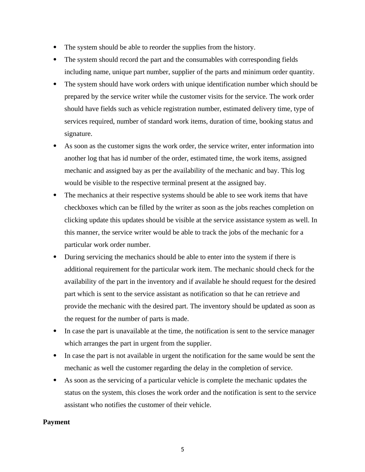
The system should be able to reorder the supplies from the history.
The system should record the part and the consumables with corresponding fields
including name, unique part number, supplier of the parts and minimum order quantity.
The system should have work orders with unique identification number which should be
prepared by the service writer while the customer visits for the service. The work order
should have fields such as vehicle registration number, estimated delivery time, type of
services required, number of standard work items, duration of time, booking status and
signature.
As soon as the customer signs the work order, the service writer, enter information into
another log that has id number of the order, estimated time, the work items, assigned
mechanic and assigned bay as per the availability of the mechanic and bay. This log
would be visible to the respective terminal present at the assigned bay.
The mechanics at their respective systems should be able to see work items that have
checkboxes which can be filled by the writer as soon as the jobs reaches completion on
clicking update this updates should be visible at the service assistance system as well. In
this manner, the service writer would be able to track the jobs of the mechanic for a
particular work order number.
During servicing the mechanics should be able to enter into the system if there is
additional requirement for the particular work item. The mechanic should check for the
availability of the part in the inventory and if available he should request for the desired
part which is sent to the service assistant as notification so that he can retrieve and
provide the mechanic with the desired part. The inventory should be updated as soon as
the request for the number of parts is made.
In case the part is unavailable at the time, the notification is sent to the service manager
which arranges the part in urgent from the supplier.
In case the part is not available in urgent the notification for the same would be sent the
mechanic as well the customer regarding the delay in the completion of service.
As soon as the servicing of a particular vehicle is complete the mechanic updates the
status on the system, this closes the work order and the notification is sent to the service
assistant who notifies the customer of their vehicle.
Payment
5
⊘ This is a preview!⊘
Do you want full access?
Subscribe today to unlock all pages.
Trusted by 1+ million students worldwide
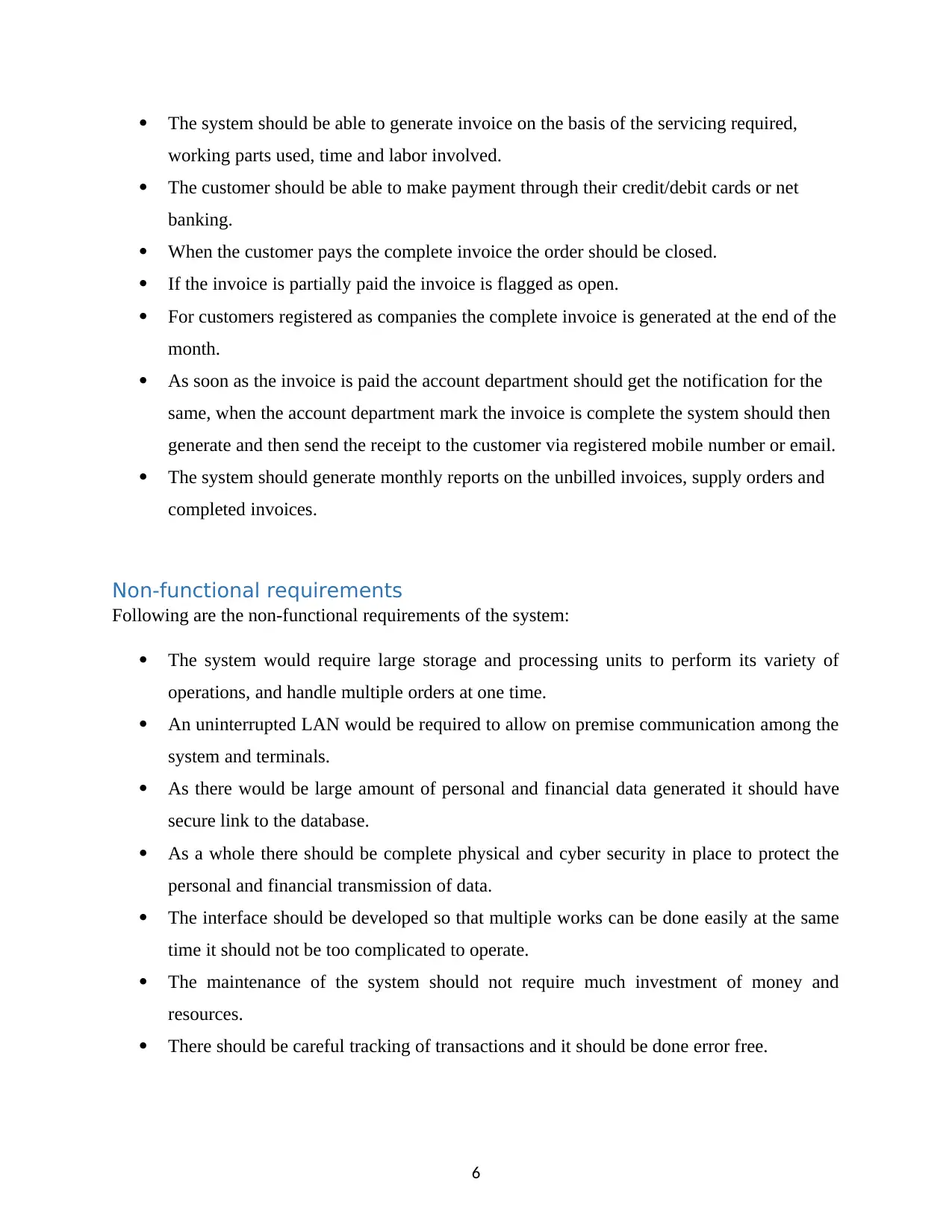
The system should be able to generate invoice on the basis of the servicing required,
working parts used, time and labor involved.
The customer should be able to make payment through their credit/debit cards or net
banking.
When the customer pays the complete invoice the order should be closed.
If the invoice is partially paid the invoice is flagged as open.
For customers registered as companies the complete invoice is generated at the end of the
month.
As soon as the invoice is paid the account department should get the notification for the
same, when the account department mark the invoice is complete the system should then
generate and then send the receipt to the customer via registered mobile number or email.
The system should generate monthly reports on the unbilled invoices, supply orders and
completed invoices.
Non-functional requirements
Following are the non-functional requirements of the system:
The system would require large storage and processing units to perform its variety of
operations, and handle multiple orders at one time.
An uninterrupted LAN would be required to allow on premise communication among the
system and terminals.
As there would be large amount of personal and financial data generated it should have
secure link to the database.
As a whole there should be complete physical and cyber security in place to protect the
personal and financial transmission of data.
The interface should be developed so that multiple works can be done easily at the same
time it should not be too complicated to operate.
The maintenance of the system should not require much investment of money and
resources.
There should be careful tracking of transactions and it should be done error free.
6
Paraphrase This Document
Need a fresh take? Get an instant paraphrase of this document with our AI Paraphraser
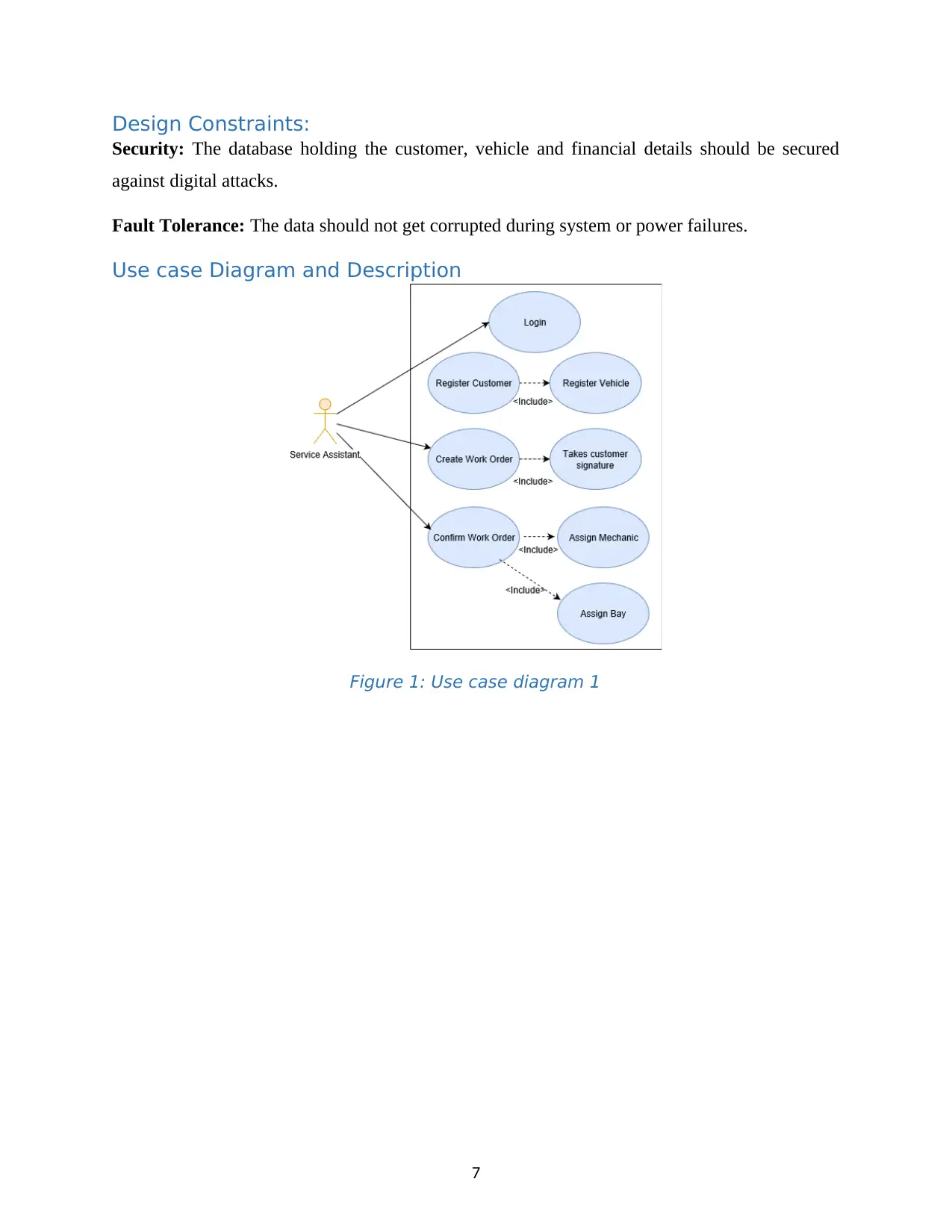
Design Constraints:
Security: The database holding the customer, vehicle and financial details should be secured
against digital attacks.
Fault Tolerance: The data should not get corrupted during system or power failures.
Use case Diagram and Description
Figure 1: Use case diagram 1
7
Security: The database holding the customer, vehicle and financial details should be secured
against digital attacks.
Fault Tolerance: The data should not get corrupted during system or power failures.
Use case Diagram and Description
Figure 1: Use case diagram 1
7
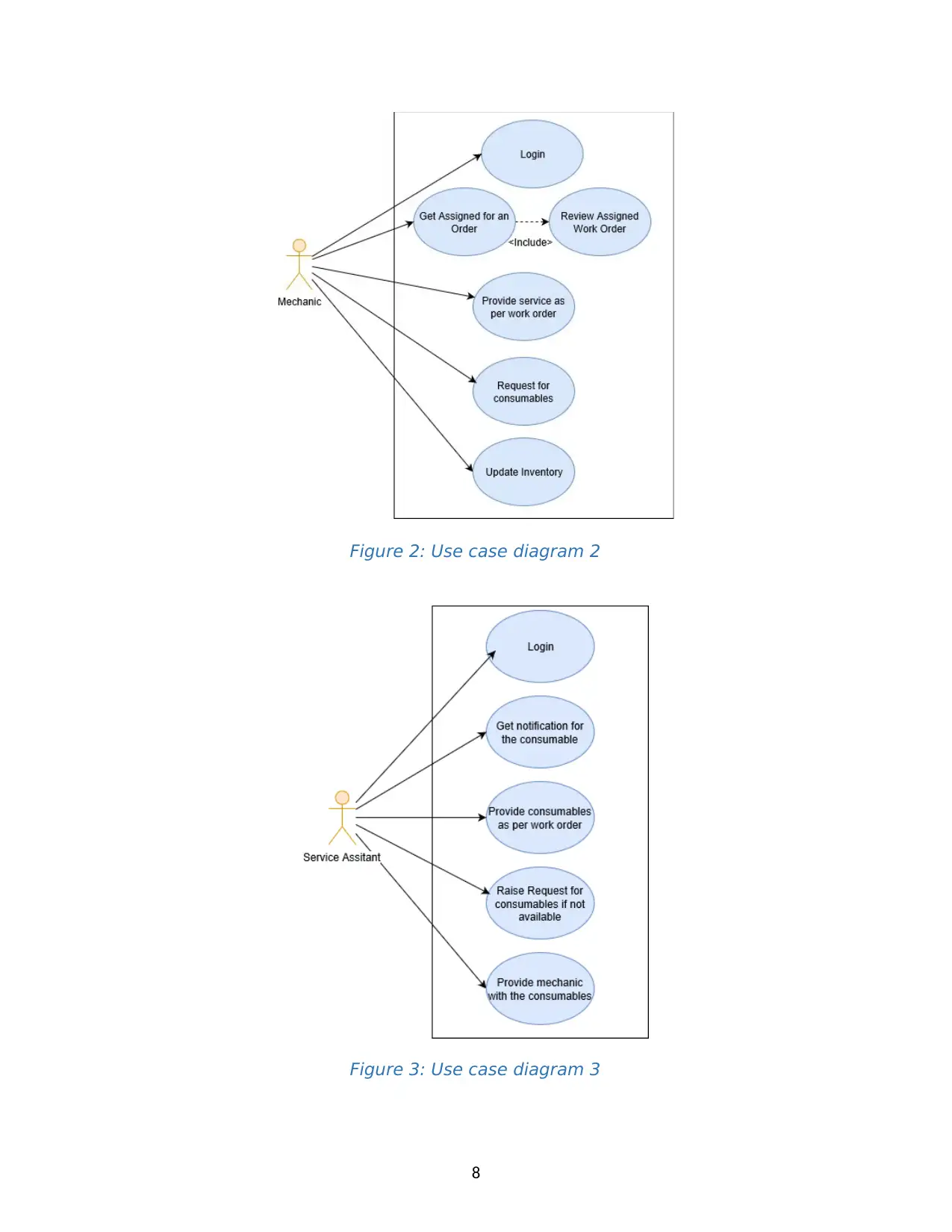
Figure 2: Use case diagram 2
Figure 3: Use case diagram 3
8
Figure 3: Use case diagram 3
8
⊘ This is a preview!⊘
Do you want full access?
Subscribe today to unlock all pages.
Trusted by 1+ million students worldwide
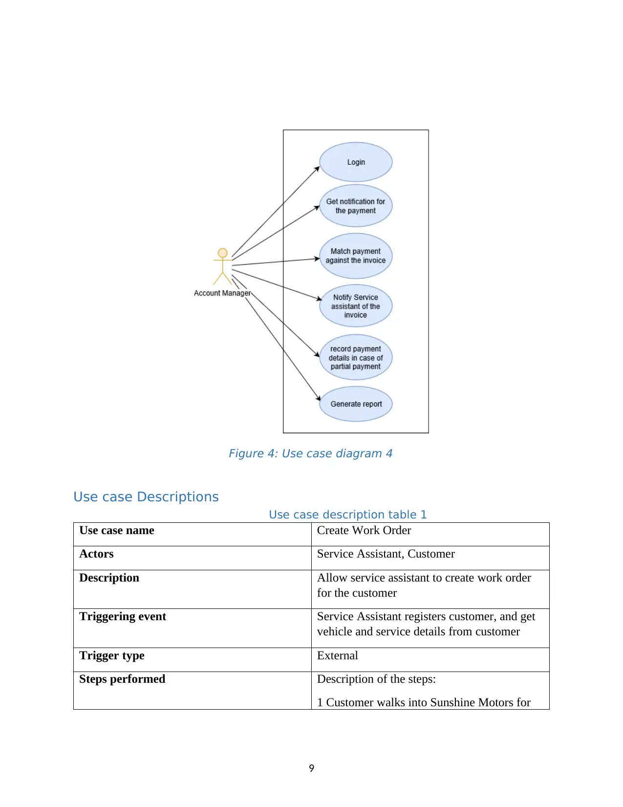
Figure 4: Use case diagram 4
Use case Descriptions
Use case description table 1
Use case name Create Work Order
Actors Service Assistant, Customer
Description Allow service assistant to create work order
for the customer
Triggering event Service Assistant registers customer, and get
vehicle and service details from customer
Trigger type External
Steps performed Description of the steps:
1 Customer walks into Sunshine Motors for
9
Paraphrase This Document
Need a fresh take? Get an instant paraphrase of this document with our AI Paraphraser
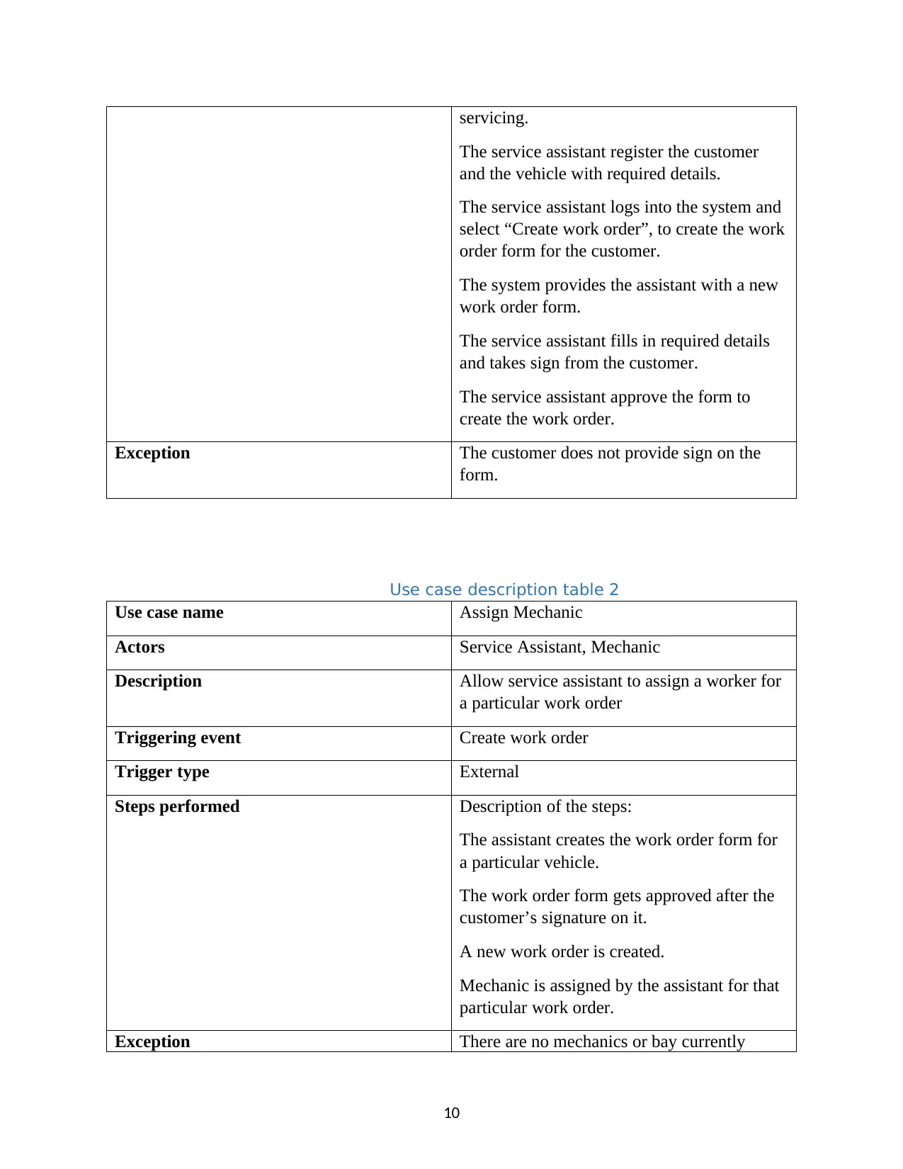
servicing.
The service assistant register the customer
and the vehicle with required details.
The service assistant logs into the system and
select “Create work order”, to create the work
order form for the customer.
The system provides the assistant with a new
work order form.
The service assistant fills in required details
and takes sign from the customer.
The service assistant approve the form to
create the work order.
Exception The customer does not provide sign on the
form.
Use case description table 2
Use case name Assign Mechanic
Actors Service Assistant, Mechanic
Description Allow service assistant to assign a worker for
a particular work order
Triggering event Create work order
Trigger type External
Steps performed Description of the steps:
The assistant creates the work order form for
a particular vehicle.
The work order form gets approved after the
customer’s signature on it.
A new work order is created.
Mechanic is assigned by the assistant for that
particular work order.
Exception There are no mechanics or bay currently
10
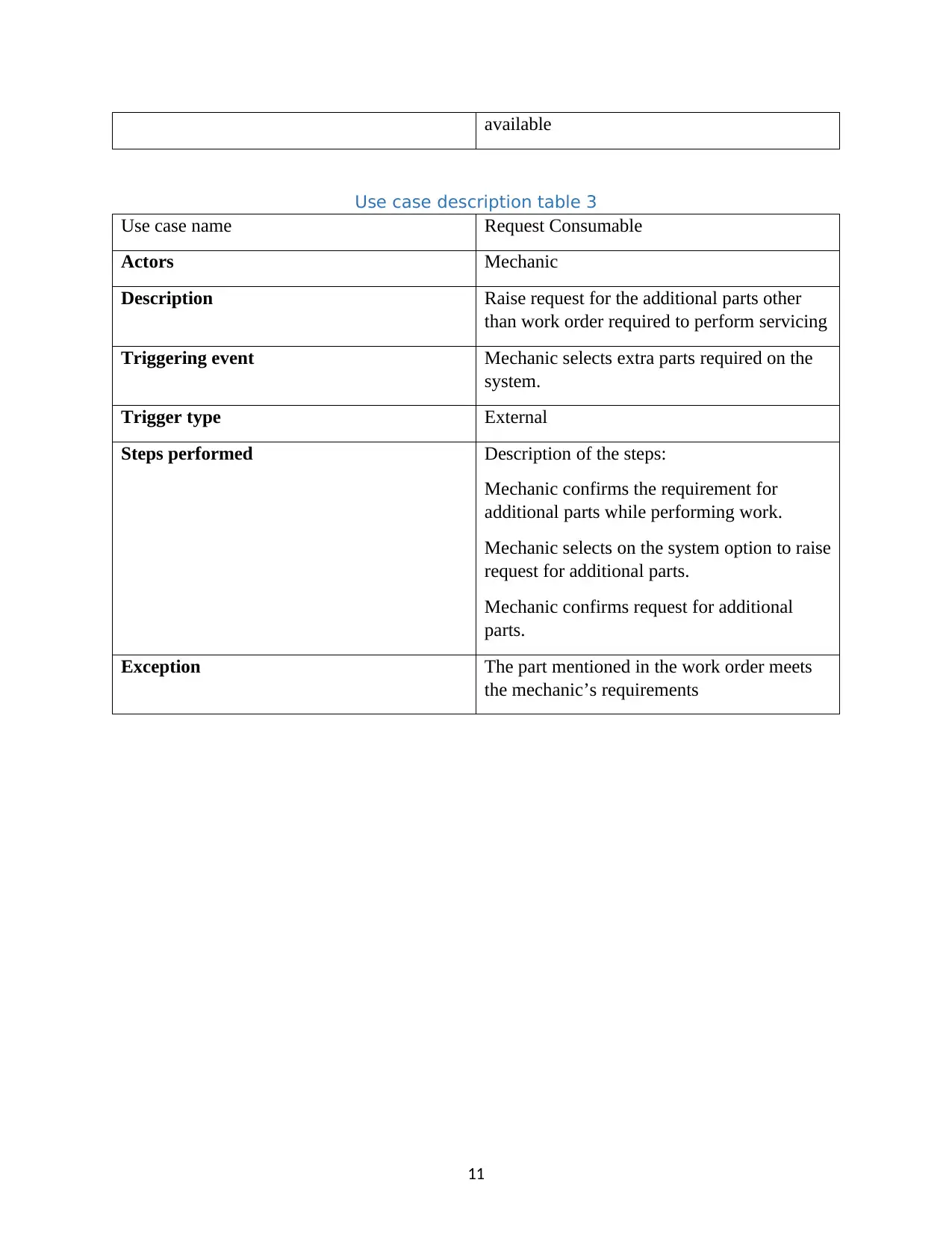
available
Use case description table 3
Use case name Request Consumable
Actors Mechanic
Description Raise request for the additional parts other
than work order required to perform servicing
Triggering event Mechanic selects extra parts required on the
system.
Trigger type External
Steps performed Description of the steps:
Mechanic confirms the requirement for
additional parts while performing work.
Mechanic selects on the system option to raise
request for additional parts.
Mechanic confirms request for additional
parts.
Exception The part mentioned in the work order meets
the mechanic’s requirements
11
⊘ This is a preview!⊘
Do you want full access?
Subscribe today to unlock all pages.
Trusted by 1+ million students worldwide
1 out of 32
Related Documents


Your All-in-One AI-Powered Toolkit for Academic Success.
+13062052269
info@desklib.com
Available 24*7 on WhatsApp / Email
![[object Object]](/_next/static/media/star-bottom.7253800d.svg)
Unlock your academic potential
Copyright © 2020–2025 A2Z Services. All Rights Reserved. Developed and managed by ZUCOL.