An analogue quantities are those quantities
10 Pages1933 Words19 Views
Added on 2022-09-05
About This Document
ELECTRONICS 4 TASKS
An analogue quantities are those quantities
Added on 2022-09-05
ShareRelated Documents
Task 1
An analogue quantities are those quantities whose magnitudes or values varies continously for
example room temperature. Digital quantities on the other hand, have a discrete set of values for
instance, digital clock
An analogue signal is an electrical waveform representing physical measurements, its amplitude
varies continously. The analoque signal signal is uniquely defined for all time values. The period
of analog signal is dependent on the frequency of the source. A digital signal on the other hand
uses discrete set of values to reprsent information. Analoq quantity consumes less bandwidth as
compared to the digital quantity.
Sensors- are modules or devices that detects a change in events or its environment and responds
to the changes by sending a signal to other electronic machines usually a processor.
Actuator- is a device that utilizes a control signal to control and move a system or mechanism.
Interface circuitry- are responsible for connecting electronics circuits such as logic gates to the
outside world.
An example of analog input that is used to control analog output is a mechanical switch or
sensors or light dependent resistors. The switch is used to control analog output which in our
case could be an LED or actuators. Input interface circuitry connects logic gates and other
electronic circuits to other devices or rather outside world. Electronics circuits process signals
from sensors or switches so as to control LED or actuators(ElectronicsTutorial, n.d). Sensors
provides information about physical quantities such as temperature, lighting and pressure. Light
dependent resistors are normally used to switch on and off LEDS. The LEDS are switched OFF
when there high light intensity and ON when light intensity is at its lowest levels
Task 2
Part A
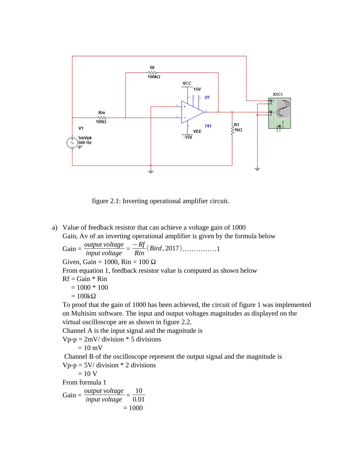
figure 2.1: Inverting operational amplifier circuit.
a) Value of feedback resistor that can achieve a voltage gain of 1000
Gain, Av of an inverting operational amplifier is given by the formula below
Gain = output voltage
input voltage = −Rf
Rin ( Bird , 2017)...............1
Given, Gain = 1000, Rin = 100 Ω
From equation 1, feedback resistor value is computed as shown below
Rf = Gain * Rin
= 1000 * 100
= 100kΩ
To proof that the gain of 1000 has been achieved, the circuit of figure 1 was implemented
on Multisim software. The input and output voltages magnitudes as displayed on the
virtual oscilloscope are as shown in figure 2.2.
Channel A is the input signal and the magnitude is
Vp-p = 2mV/ division * 5 divisions
= 10 mV
Channel B of the oscilloscope represent the output signal and the magnitude is
Vp-p = 5V/ division * 2 divisions
= 10 V
From formula 1
Gain = output voltage
input voltage = 10
0.01
= 1000
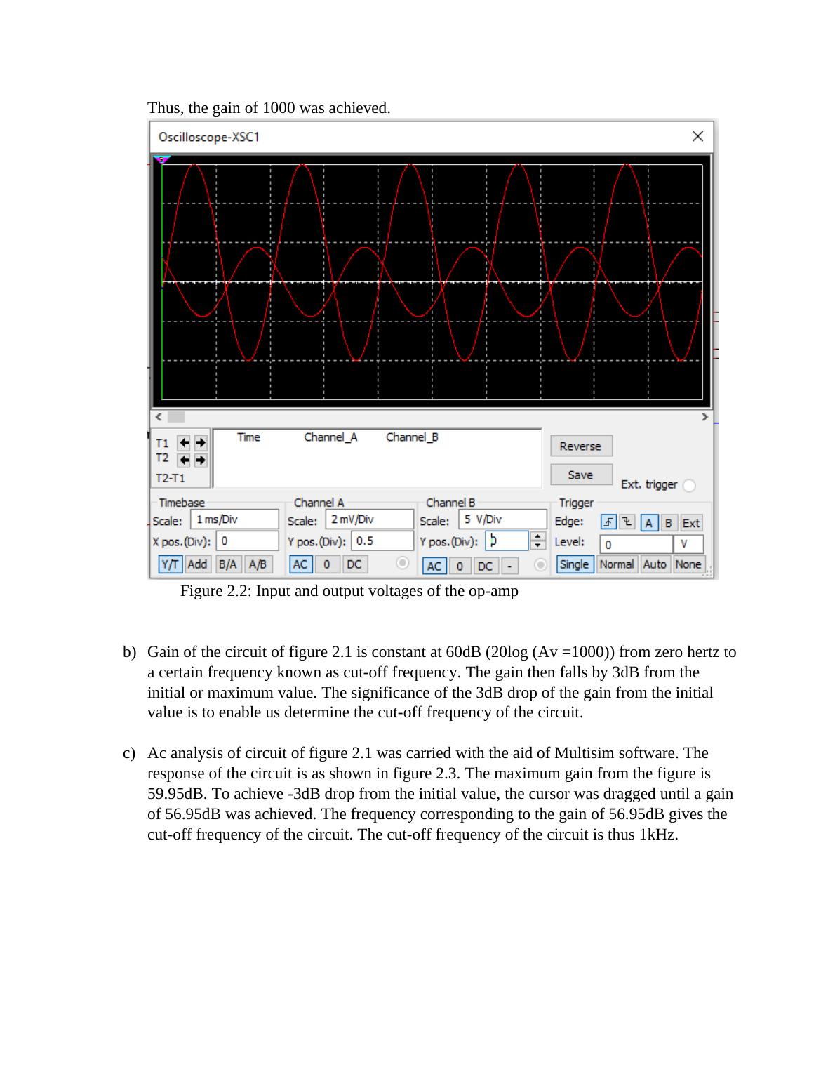
Thus, the gain of 1000 was achieved.
Figure 2.2: Input and output voltages of the op-amp
b) Gain of the circuit of figure 2.1 is constant at 60dB (20log (Av =1000)) from zero hertz to
a certain frequency known as cut-off frequency. The gain then falls by 3dB from the
initial or maximum value. The significance of the 3dB drop of the gain from the initial
value is to enable us determine the cut-off frequency of the circuit.
c) Ac analysis of circuit of figure 2.1 was carried with the aid of Multisim software. The
response of the circuit is as shown in figure 2.3. The maximum gain from the figure is
59.95dB. To achieve -3dB drop from the initial value, the cursor was dragged until a gain
of 56.95dB was achieved. The frequency corresponding to the gain of 56.95dB gives the
cut-off frequency of the circuit. The cut-off frequency of the circuit is thus 1kHz.
End of preview
Want to access all the pages? Upload your documents or become a member.