Compact Vector Network Analyzer Design
VerifiedAdded on 2020/09/17
|14
|2343
|114
AI Summary
This assignment guides students through the design of a compact vector network analyzer (VNA). It begins with validating the approach using ideal circuit simulations in ADS by Agilent. Then, it introduces components and their parameters into the simulation model to assess impairments on VNA outcomes. The design process is detailed, including electrical schematics, a DDS1 generator, detector, clock generator, USB interface, power supply, and PC board connections. Measurements are run, and results are compared with expected values. References are provided for further study.
Contribute Materials
Your contribution can guide someone’s learning journey. Share your
documents today.

TCP/IP
IP Address Management
IP Address Management
Secure Best Marks with AI Grader
Need help grading? Try our AI Grader for instant feedback on your assignments.
To achieve efficient IP address management, businesses must first formulate
a strategy that caters to their specifications. While chalking out this plan,
administrators need to focus on 3 major components of IP management: IP
Address Inventory Administration, Domain Name Service (DNS)
Management, and Dynamic Host Settings Protocol (DHCP) Management.
TCP/IP Model
While the OSI strategies slowly developed, due to their official committee
based mainly
Engineering, technique, the TCP/IP protocol package deal evolved and
matured. Using its public Request for Comments (RFC) policy of improving
plus updating the protocol selection, it has established itself because the
protocol of choice for many data communication networks.
TCP/IP is the internationally accepted normal for local networks, networking
and internet. TCP (Transmission Control Protocol) + Internet Protocol (IP)
TCP = the connection process.
Internet Protocol = the specific routing protocol.
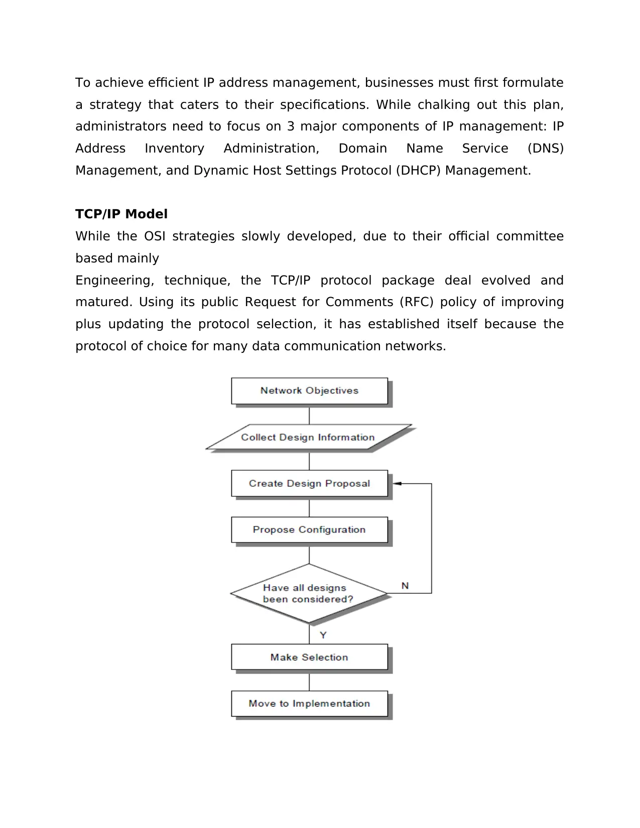
Network Design Steps
Below is a typical rule-of-thumb approach to IP program design. It presents
the structured approach to analyzing in addition developing a network
design to suit the needs of a company.
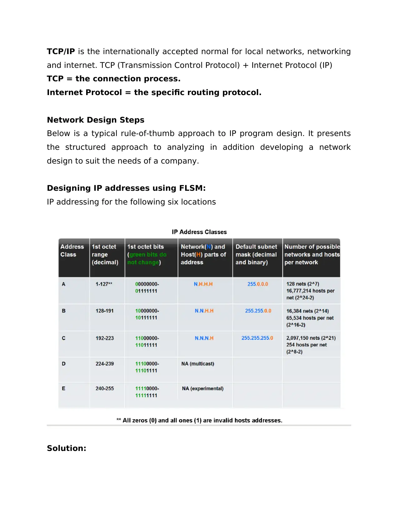
Designing IP addresses using FLSM:
IP addressing for the following six locations
Solution:

From the given network address, the subletting must be done using the last
octet (last 8 bits).
-------------- network portion --------- host portion
192 168 . 10 0 Decimal form
1100 0000 . 1010 1000 . 0000 1010 . 0000 0000 Binary form
As the company has 4 departments, you need to have 4 subnets and each of
those subnets must accommodate all the PCs and printers. Each network will
need an address for the gateway. So for each subnet we need 20 PCs + 3
printers + 1 gateway = 24 IPs. We have 8 bits in the last octet of the
network address (host portion in the given network address). Among these
we have to decide how many bits for host part and how many bits for subnet
part.
To find the number of bits needed to accommodate m hosts the formula is:
2n - 2 ≥ m
Where n is the number of host bits and m is the total number of host IPs
needed. Using this formula for 24 hosts, we need 5 bits. (25 - 2 = 30 ≥ 23)
If the last octet is considered,
0 0 0 0 0 0 0 0
|-sub net part-|-----host part--------|
The new subnet mask can be found after deciding on the number of host
bits, by the following formula. Host bits are the last few bits. So (32 - n) will
be the subnet mask number which is 32 - 5 = 27 here. Subnet mask is /27
and in decimal form it is 27 ones among 32 bits.
Subnet mask in prefix notation: /27
Subnet mask in binary form: 1111 1111. 1111 1111. 1111 1111. 1110 0000
Subnet Mask in decimal form:255 255 . 255 . 224
Secure Best Marks with AI Grader
Need help grading? Try our AI Grader for instant feedback on your assignments.
The four network addresses are: only last octet is shown:
.000 00000 = .0
.001 00000 = .32
.010 00000 = .64
.011 00000 = .96
Now try to fill up the following table which has all the needed IP addresses
for the network topology.
S.No Subnet Subnet Network Fist usable Last usable Broadcast
Mask addresses address address address
1 Department A /27 192.168.10.0 192.168.10.1
192.168.10.30 192.168.10.31
2 Department B /27 192.168.10.32 192.168.10.33
192.168.10.62 192.168.10.63
3 Department C /27 192.168.10.64 192.168.10.65
192.168.10.94 192.168.10.95
4 Department E /27 192.168.10.96 192.168.10.97
192.168.10.126 192.168.10.127
Allocate the IP addresses from the first usable to last usable IPs rage to all
the PCs, printers and gateway in the respective departments.
IP address Design using FLSM:
Given an IP network address and mask of 172.20.0.0 / 24 (address / mask),
design an IP addressing scheme that satisfies the following requirements:
Subnet Number of Hosts
Subnet A 2
Subnet B 6
Subnet C 47
Subnet D 125
Host computers from each subnet will use the first available IP address in the
address block. Router interfaces will use the last available IP address in the
address block.
Start with largest host requirement network.
Step 1: Design Subnet D address block.
Begin the logical network design by satisfying the requirement of Subnet D,
which requires the largest block of IP addresses. Refer to the subnet chart,
and pick the first address block that will support Subnet D.
First find the subnet mask by calculating the number of bits needed for the
hosts in the network using the formula
2n - 2 ≥ m
Where n is the number of host bits and m is the total number of host IPs
needed. Here 2n - 2 ≥ 125, so n will be 7
To find the subnet mask using n use the formula: subnet mask = 32 - n
Mask is 32 - 7 = /25
Network address of the first network will be the given network address. First
host address will be one greater than network address.
Broad cast address will be the address one less than the next network
address. Last usable address will be the address one less than the broadcast
address. So it will be easy to find Broadcast addresses and last usable
address after finding the next network address.
To find the next network address, use this formula:
Next network address is = current network address + 2n
Here the next network address = 172.20.0.0 + 27 = 172.20.0.0 + 128 =
172.20.0.128
One less than this address will be broadcast - 172.20.0.127 and one less
than this will be last usable address 172.20.0.126
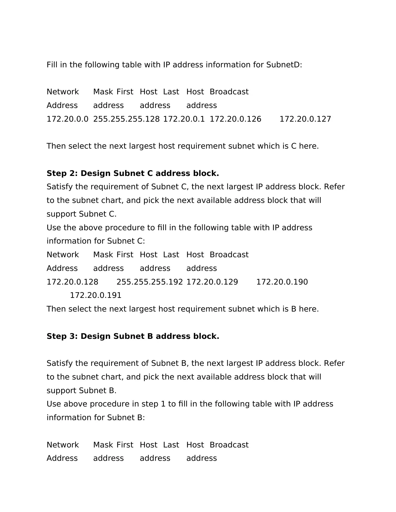
Fill in the following table with IP address information for SubnetD:
Network Mask First Host Last Host Broadcast
Address address address address
172.20.0.0 255.255.255.128 172.20.0.1 172.20.0.126 172.20.0.127
Then select the next largest host requirement subnet which is C here.
Step 2: Design Subnet C address block.
Satisfy the requirement of Subnet C, the next largest IP address block. Refer
to the subnet chart, and pick the next available address block that will
support Subnet C.
Use the above procedure to fill in the following table with IP address
information for Subnet C:
Network Mask First Host Last Host Broadcast
Address address address address
172.20.0.128 255.255.255.192 172.20.0.129 172.20.0.190
172.20.0.191
Then select the next largest host requirement subnet which is B here.
Step 3: Design Subnet B address block.
Satisfy the requirement of Subnet B, the next largest IP address block. Refer
to the subnet chart, and pick the next available address block that will
support Subnet B.
Use above procedure in step 1 to fill in the following table with IP address
information for Subnet B:
Network Mask First Host Last Host Broadcast
Address address address address
Network Mask First Host Last Host Broadcast
Address address address address
172.20.0.0 255.255.255.128 172.20.0.1 172.20.0.126 172.20.0.127
Then select the next largest host requirement subnet which is C here.
Step 2: Design Subnet C address block.
Satisfy the requirement of Subnet C, the next largest IP address block. Refer
to the subnet chart, and pick the next available address block that will
support Subnet C.
Use the above procedure to fill in the following table with IP address
information for Subnet C:
Network Mask First Host Last Host Broadcast
Address address address address
172.20.0.128 255.255.255.192 172.20.0.129 172.20.0.190
172.20.0.191
Then select the next largest host requirement subnet which is B here.
Step 3: Design Subnet B address block.
Satisfy the requirement of Subnet B, the next largest IP address block. Refer
to the subnet chart, and pick the next available address block that will
support Subnet B.
Use above procedure in step 1 to fill in the following table with IP address
information for Subnet B:
Network Mask First Host Last Host Broadcast
Address address address address
Paraphrase This Document
Need a fresh take? Get an instant paraphrase of this document with our AI Paraphraser
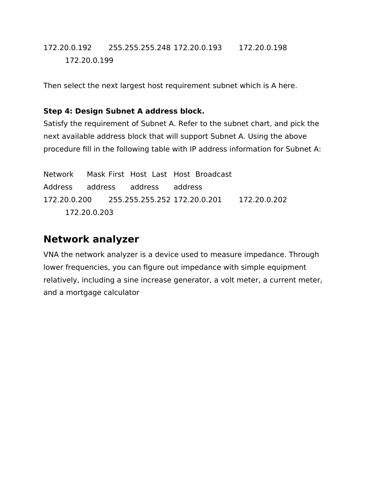
172.20.0.192 255.255.255.248 172.20.0.193 172.20.0.198
172.20.0.199
Then select the next largest host requirement subnet which is A here.
Step 4: Design Subnet A address block.
Satisfy the requirement of Subnet A. Refer to the subnet chart, and pick the
next available address block that will support Subnet A. Using the above
procedure fill in the following table with IP address information for Subnet A:
Network Mask First Host Last Host Broadcast
Address address address address
172.20.0.200 255.255.255.252 172.20.0.201 172.20.0.202
172.20.0.203
Network analyzer
VNA the network analyzer is a device used to measure impedance. Through
lower frequencies, you can figure out impedance with simple equipment
relatively, including a sine increase generator, a volt meter, a current meter,
and a mortgage calculator
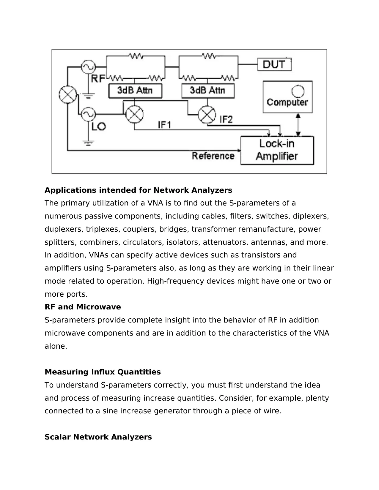
Applications intended for Network Analyzers
The primary utilization of a VNA is to find out the S-parameters of a
numerous passive components, including cables, filters, switches, diplexers,
duplexers, triplexes, couplers, bridges, transformer remanufacture, power
splitters, combiners, circulators, isolators, attenuators, antennas, and more.
In addition, VNAs can specify active devices such as transistors and
amplifiers using S-parameters also, as long as they are working in their linear
mode related to operation. High-frequency devices might have one or two or
more ports.
RF and Microwave
S-parameters provide complete insight into the behavior of RF in addition
microwave components and are in addition to the characteristics of the VNA
alone.
Measuring Influx Quantities
To understand S-parameters correctly, you must first understand the idea
and process of measuring increase quantities. Consider, for example, plenty
connected to a sine increase generator through a piece of wire.
Scalar Network Analyzers
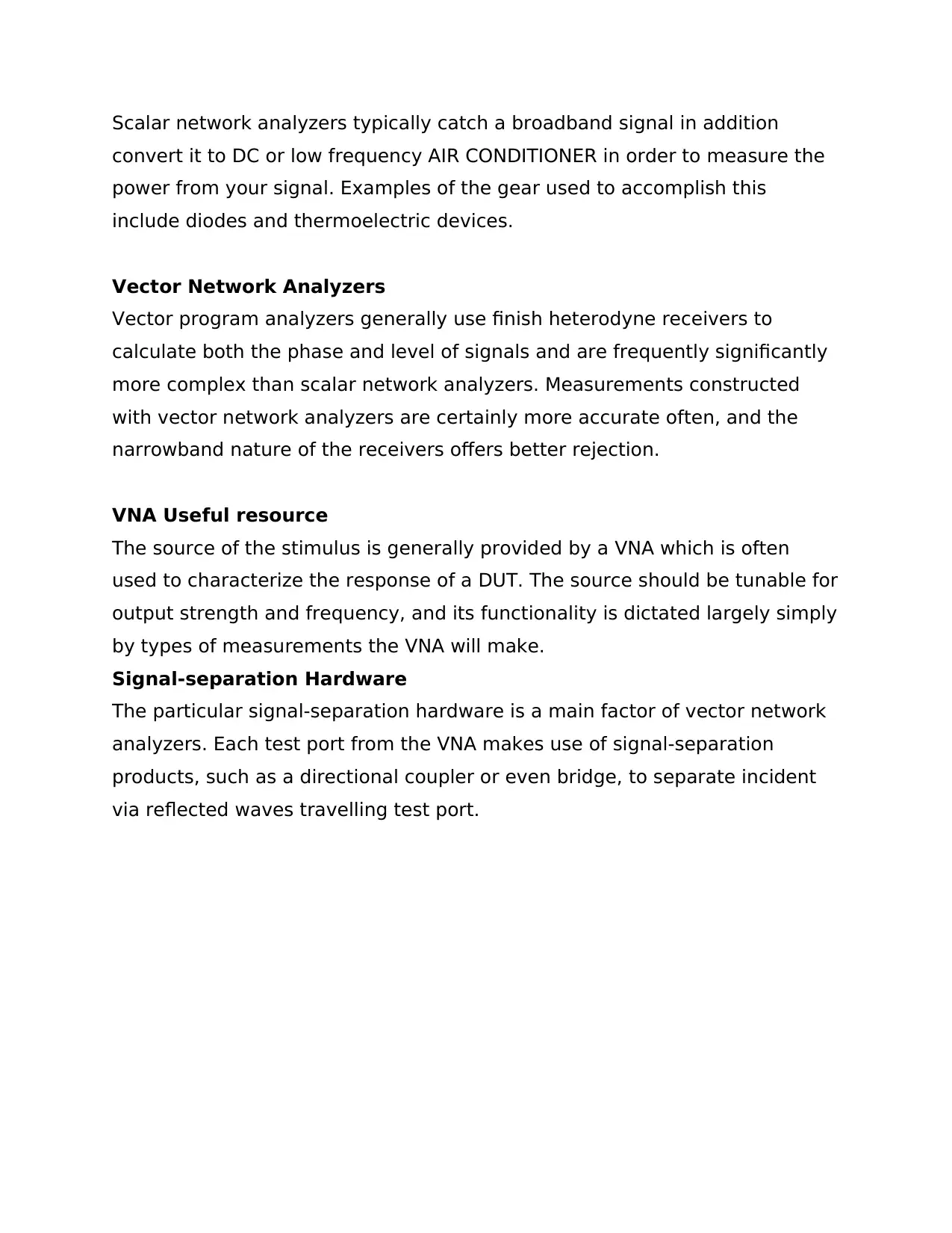
Scalar network analyzers typically catch a broadband signal in addition
convert it to DC or low frequency AIR CONDITIONER in order to measure the
power from your signal. Examples of the gear used to accomplish this
include diodes and thermoelectric devices.
Vector Network Analyzers
Vector program analyzers generally use finish heterodyne receivers to
calculate both the phase and level of signals and are frequently significantly
more complex than scalar network analyzers. Measurements constructed
with vector network analyzers are certainly more accurate often, and the
narrowband nature of the receivers offers better rejection.
VNA Useful resource
The source of the stimulus is generally provided by a VNA which is often
used to characterize the response of a DUT. The source should be tunable for
output strength and frequency, and its functionality is dictated largely simply
by types of measurements the VNA will make.
Signal-separation Hardware
The particular signal-separation hardware is a main factor of vector network
analyzers. Each test port from the VNA makes use of signal-separation
products, such as a directional coupler or even bridge, to separate incident
via reflected waves travelling test port.
Secure Best Marks with AI Grader
Need help grading? Try our AI Grader for instant feedback on your assignments.
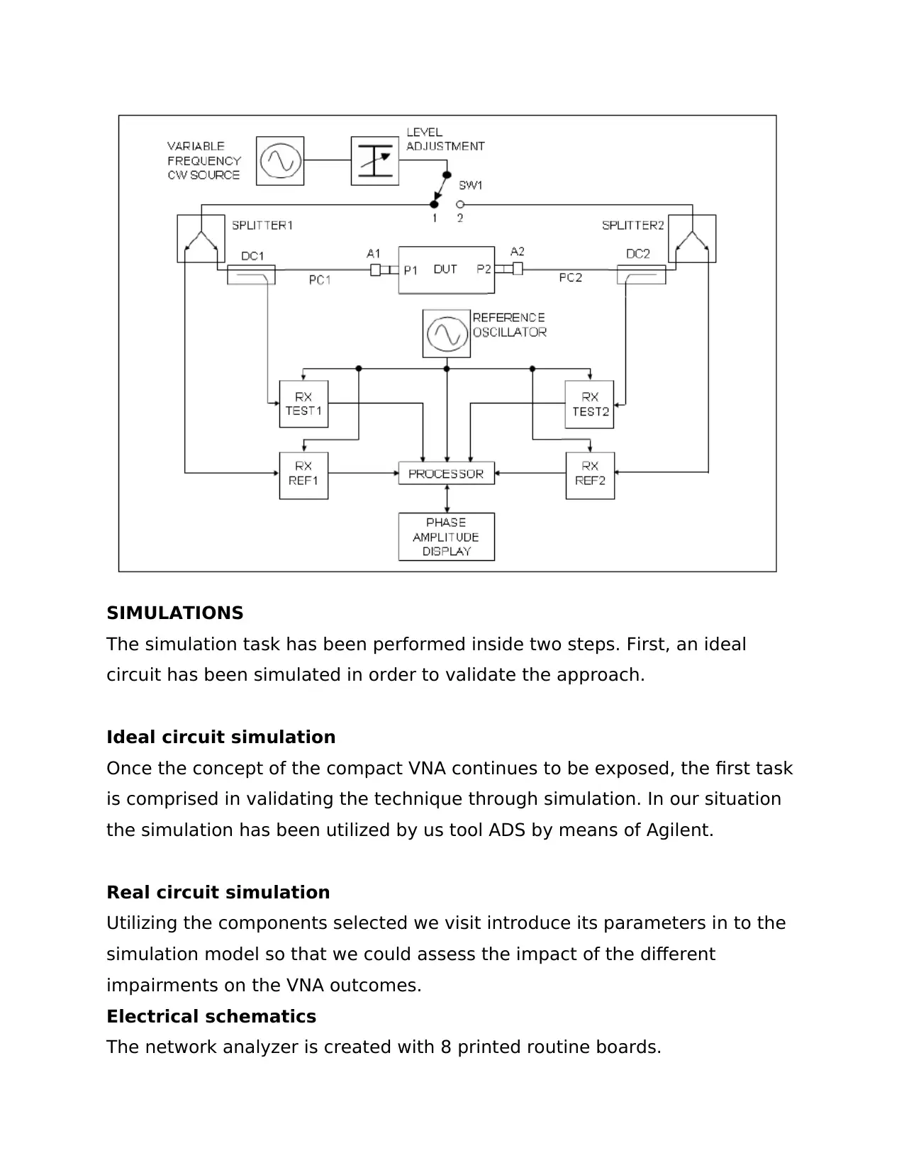
SIMULATIONS
The simulation task has been performed inside two steps. First, an ideal
circuit has been simulated in order to validate the approach.
Ideal circuit simulation
Once the concept of the compact VNA continues to be exposed, the first task
is comprised in validating the technique through simulation. In our situation
the simulation has been utilized by us tool ADS by means of Agilent.
Real circuit simulation
Utilizing the components selected we visit introduce its parameters in to the
simulation model so that we could assess the impact of the different
impairments on the VNA outcomes.
Electrical schematics
The network analyzer is created with 8 printed routine boards.
o DDS1 generator
o DDS2 generator
o Detector (A)
o Metal detector (R), the (A) detector and the (R) detector are often
identical
o A hundred and fifty MHz clock generator
o an USB interface
o a power supply
o The particular clock generator to get a time clock needed by the
analog to be able to digital converters
All the PC boards are connected together with wires and coaxial wires.
The measurements:
o The new that we run the analyzer, connect the output (A) in order to
input (A), and the result (R) to input (R), (with the short cables).
o Run the F measure software application.
o Choose to measure: get (U) vs frequency; examine from 1kHz to
60MHz
o The gain must be nearly constant and probably in between 0. 9 and
one ) 1
o If we remove the cable on the (A) input, the gain needs to be zero.
o Now, to correct the particular bad symmetry between the (A) channel
and the (R) approach, press the "F5" important and follow the
indications constructed onto the screen.
o By this way, the lack is set by us of percentage “not frequency
conditional ".
o The “period “correction allows paying for the difference of length
among (A) channel and the (R) channel.
REFERENCES
[1] Beyond DHCP - Work Your TCP/IP Internetwork with Dynamic IP, SG24-
5280
[2] MSS Release 2.1, Including MSS Client Domain Client, SG24-5231
[3] Customer-Implemented Networking Campus Solution II, SG24-5226
[4] Local Area Network Concepts and Products: LAN Architecture, SG24-4753
[5] Agilent Technologies, "Network Analyzer Basics," 31 Auguts 2004.
[Online]. Available: http://cp.literature.agilent.com/litweb/pdf/5965-
7917E.pdf. [Accessed 16 November 2012].
[6] B. A. Brown, "Solving the One-Port Calibration Equations," 2004. [Online].
Available: http://na.tm.agilent.com/vnahelp/tip20.html. [Accessed 15 August
2013].
[7] M. Fallahpour, M. Baumgartner, A. Kothari, M. Ghasr, D. Pommerenke and
R. Zoughi, "Compact Ka-Band One-Port Vector Reflectometer Using a
Wideband Electronically Controlled Phase Shifter," Instrumentation and
Measurement, IEEE Transactions on, vol. 61, no. 10, pp. 2807,2816, Oct.
2012.
[8] K. Kim, N. Kim, S.-H. Hwang, Y.-K. Kim and Y. Kwon, "A Miniaturized
Broadband Multi-State Reflectometer Integrated on a Silicon MEMS Probe for
Complex Permittivity Measurement of Biological Material," Microwave Theory
and Techniques, IEEE Transactions on, vol. 61, no. 5, pp. 2205,2214, May
2013.
Paraphrase This Document
Need a fresh take? Get an instant paraphrase of this document with our AI Paraphraser

1 out of 14
Related Documents
Your All-in-One AI-Powered Toolkit for Academic Success.
+13062052269
info@desklib.com
Available 24*7 on WhatsApp / Email
![[object Object]](/_next/static/media/star-bottom.7253800d.svg)
Unlock your academic potential
© 2024 | Zucol Services PVT LTD | All rights reserved.


