Technical Paper on CFD Analysis of Screw Compressor Using ANSYS
VerifiedAdded on 2023/01/18
|13
|1599
|50
Report
AI Summary
This technical paper presents a comprehensive CFD analysis of a screw compressor, focusing on rotor performance under various operating conditions. The study utilizes ANSYS software to simulate the compressor's behavior, examining parameters such as pressure distribution, velocity profiles, and structural integrity. The paper details the methodology, including the development of a 3D model, finite element analysis (FEA), and the application of boundary conditions for both normal and non-normal operating states. Key findings include the exhaust pressure values and velocity streamline patterns. The report also incorporates material properties, design checks, and a discussion of potential optimization strategies to improve the compressor's efficiency, including clearance and material selection. The conclusion emphasizes the significance of CFD analysis in validating the design and identifying areas for further enhancements. The paper also includes references to related research and industry standards.
TECHNICAL PAPER ON CFD ANALYSIS OF SCREW
COMPRESSOR USING ANSYS
COMPRESSOR USING ANSYS
Paraphrase This Document
Need a fresh take? Get an instant paraphrase of this document with our AI Paraphraser
Abstract:
The demand of screw compressor is high because of its efficiency and user demand. Screw type rotary
compressor is rotary type compressor based on positive displacement mechanism. This type of compressor is
made to replace the conventional cylinder piston type compressor which requires high pressure for the
operation. This reduces the pulsating and surging which is produced in the piston type compressor. The screw
compressor has a tip speed of 100 m/s with outlet temperature of around 250 degree. For the designing of the
screw compressor the clearance between the rotor and the casing plays an important role. This CFD analysis is
to calculated the external forces developed, pressure developed during the operation. The result and the
analysis are presented in the paper.
Introduction:
Screw compressor is helical rotor is housed in the housing of the screw compressor. The other rotor attached
outside the pitch circle diameter with the compressor rotor is know as the main rotor. This is attached to the
main motor of the screw compressor. The principle of operation is same as piston type compressor. One rotor
act as the piston and other as the cylinder to increase the air pressure.
The screw compressor us divided into following category based on the application principle.
Oil Flooded Compressor
1. Air Compressor
2. Refrigeration Compressor
3. Process Gas Compressor
Oil Free Compressor
1. Dry Compressor
2. Water In jet Compressor
The main feature is the gap between the rotor as that gap will create the pressure in the air.
Theoretical Approach:
The performance of the compressor is dependent on the following parameters
Sealing Line Length
Blow Hole Area
Radial Clearance
Interlope Clearance
Axial Clearance
Sealing line length is the meshing of surface of surface of the male and female rotor. The space generated is the
curve surface.
Blow Hole Area is the tip of the contact line of the rotor. This is dependent on the application of the screw
compressor
All the clearance is dependent on the following parameters
1. Structural deflection of the rotors due to pressure
2. Structural expansion of the housing bores due to pressure
3. Torsional twist of the rotors
4. Backlash of the synchronizing gears (incase of dry and water injected Compressors)
5. Thermal expansion of rotors due to the thermal loading due to compression
6. Thermal expansion of housing bore due to the thermal loading due to compression
7. Thermal expansion of the housing center distance of the bores due to thermal loading
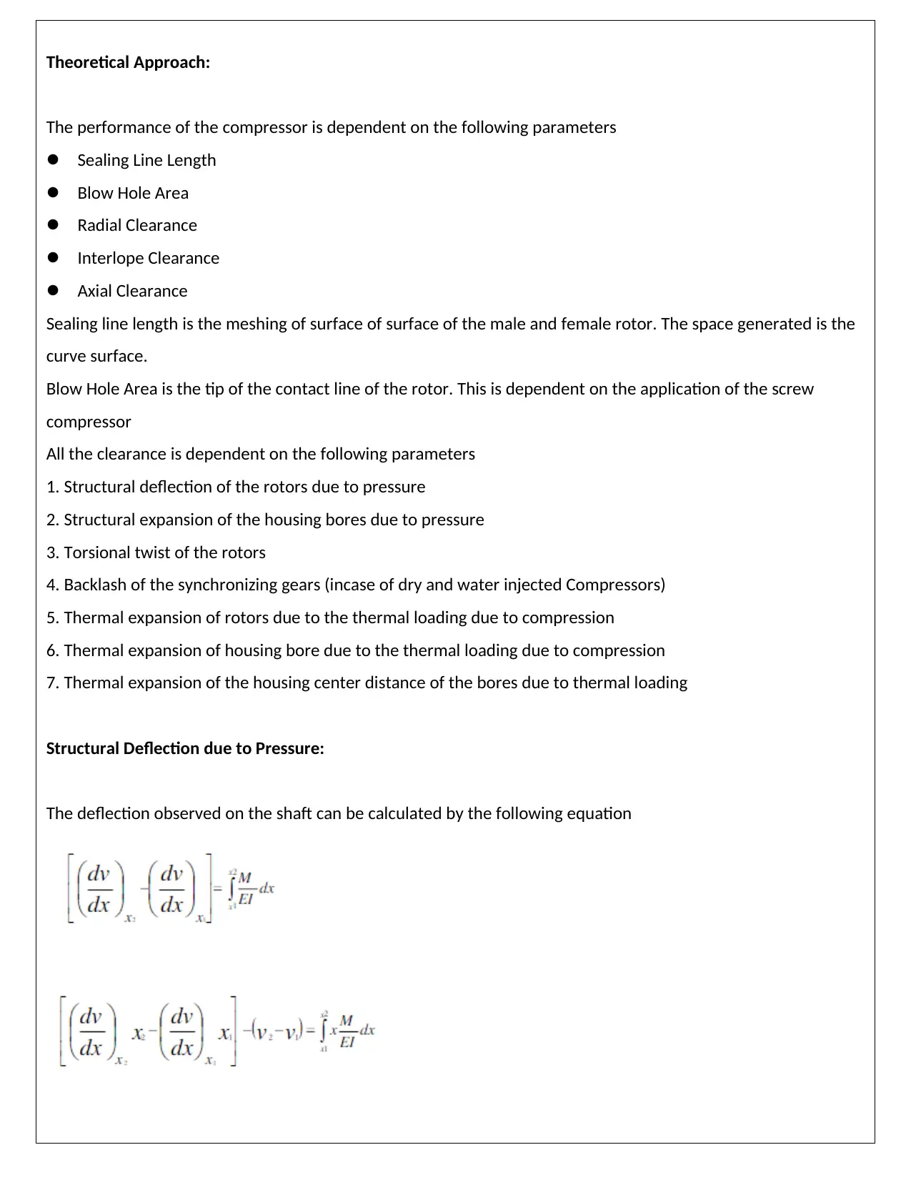
Structural Deflection due to Pressure:
The deflection observed on the shaft can be calculated by the following equation
⊘ This is a preview!⊘
Do you want full access?
Subscribe today to unlock all pages.

Trusted by 1+ million students worldwide
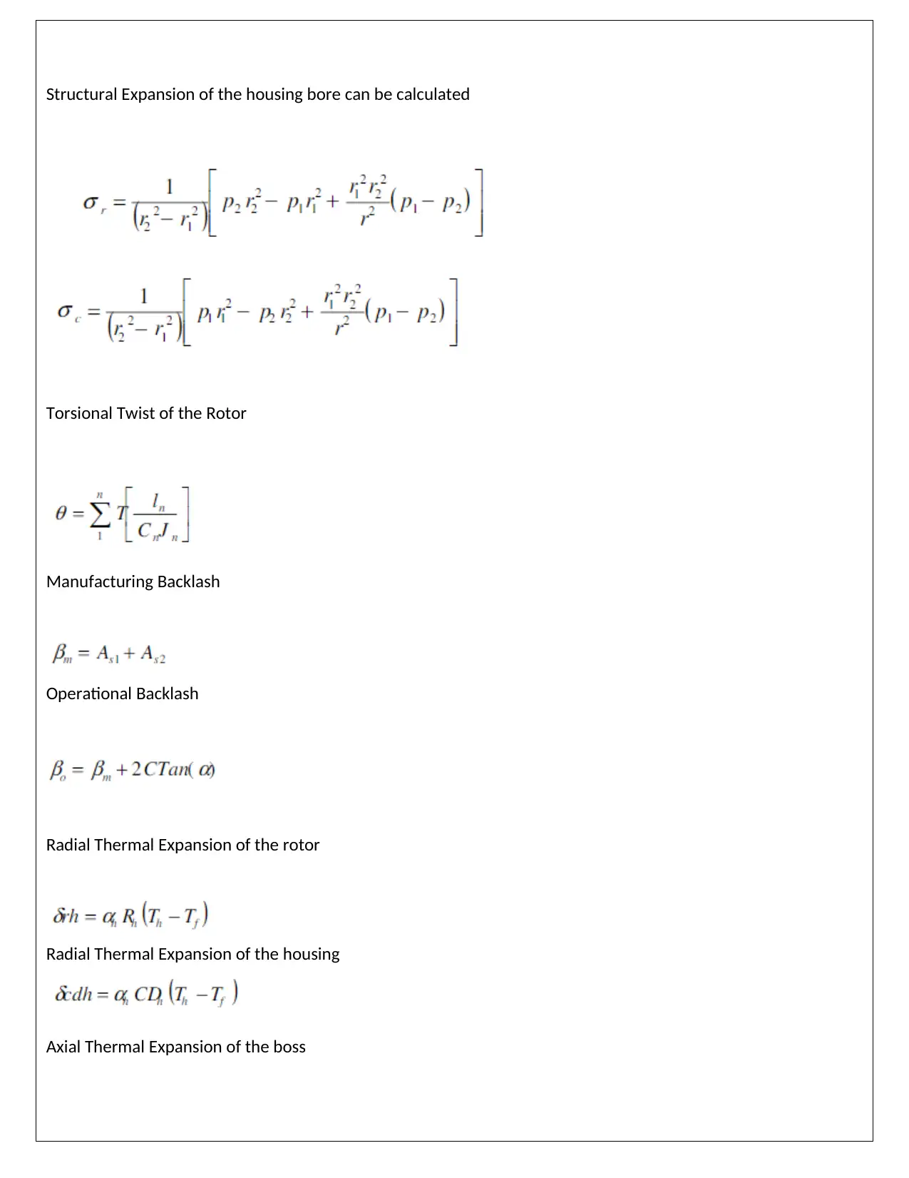
Structural Expansion of the housing bore can be calculated
Torsional Twist of the Rotor
Manufacturing Backlash
Operational Backlash
Radial Thermal Expansion of the rotor
Radial Thermal Expansion of the housing
Axial Thermal Expansion of the boss
Torsional Twist of the Rotor
Manufacturing Backlash
Operational Backlash
Radial Thermal Expansion of the rotor
Radial Thermal Expansion of the housing
Axial Thermal Expansion of the boss
Paraphrase This Document
Need a fresh take? Get an instant paraphrase of this document with our AI Paraphraser
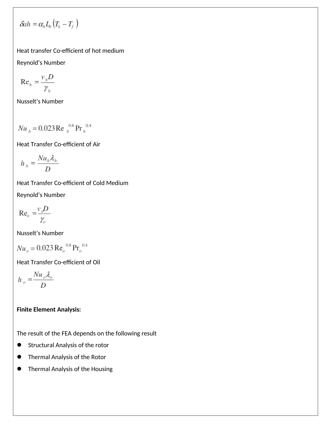
Heat transfer Co-efficient of hot medium
Reynold’s Number
Nusselt’s Number
Heat Transfer Co-efficient of Air
Heat Transfer Co-efficient of Cold Medium
Reynold’s Number
Nusselt’s Number
Heat Transfer Co-efficient of Oil
Finite Element Analysis:
The result of the FEA depends on the following result
Structural Analysis of the rotor
Thermal Analysis of the Rotor
Thermal Analysis of the Housing
Reynold’s Number
Nusselt’s Number
Heat Transfer Co-efficient of Air
Heat Transfer Co-efficient of Cold Medium
Reynold’s Number
Nusselt’s Number
Heat Transfer Co-efficient of Oil
Finite Element Analysis:
The result of the FEA depends on the following result
Structural Analysis of the rotor
Thermal Analysis of the Rotor
Thermal Analysis of the Housing
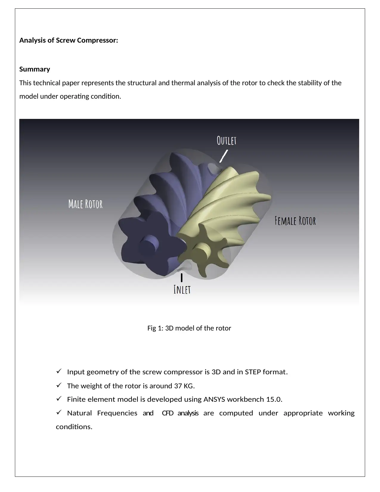
Analysis of Screw Compressor:
Summary
This technical paper represents the structural and thermal analysis of the rotor to check the stability of the
model under operating condition.
Fig 1: 3D model of the rotor
Input geometry of the screw compressor is 3D and in STEP format.
The weight of the rotor is around 37 KG.
Finite element model is developed using ANSYS workbench 15.0.
Natural Frequencies and CFD analysis are computed under appropriate working
conditions.
⊘ This is a preview!⊘
Do you want full access?
Subscribe today to unlock all pages.

Trusted by 1+ million students worldwide
Problem Definition and Input Supplied
Scope of Work
The Objective of the analysis is to perform a computer aided simulation so as to ascertain the mechanical
integrity of the rotor when subjected to Load Environment like pressure and temperature. The following
parameter are investigated and illustrated in the report.
Deformations at points of interest.
Velocity Profile.
Pressure distribution profile.
Specification of Analysis
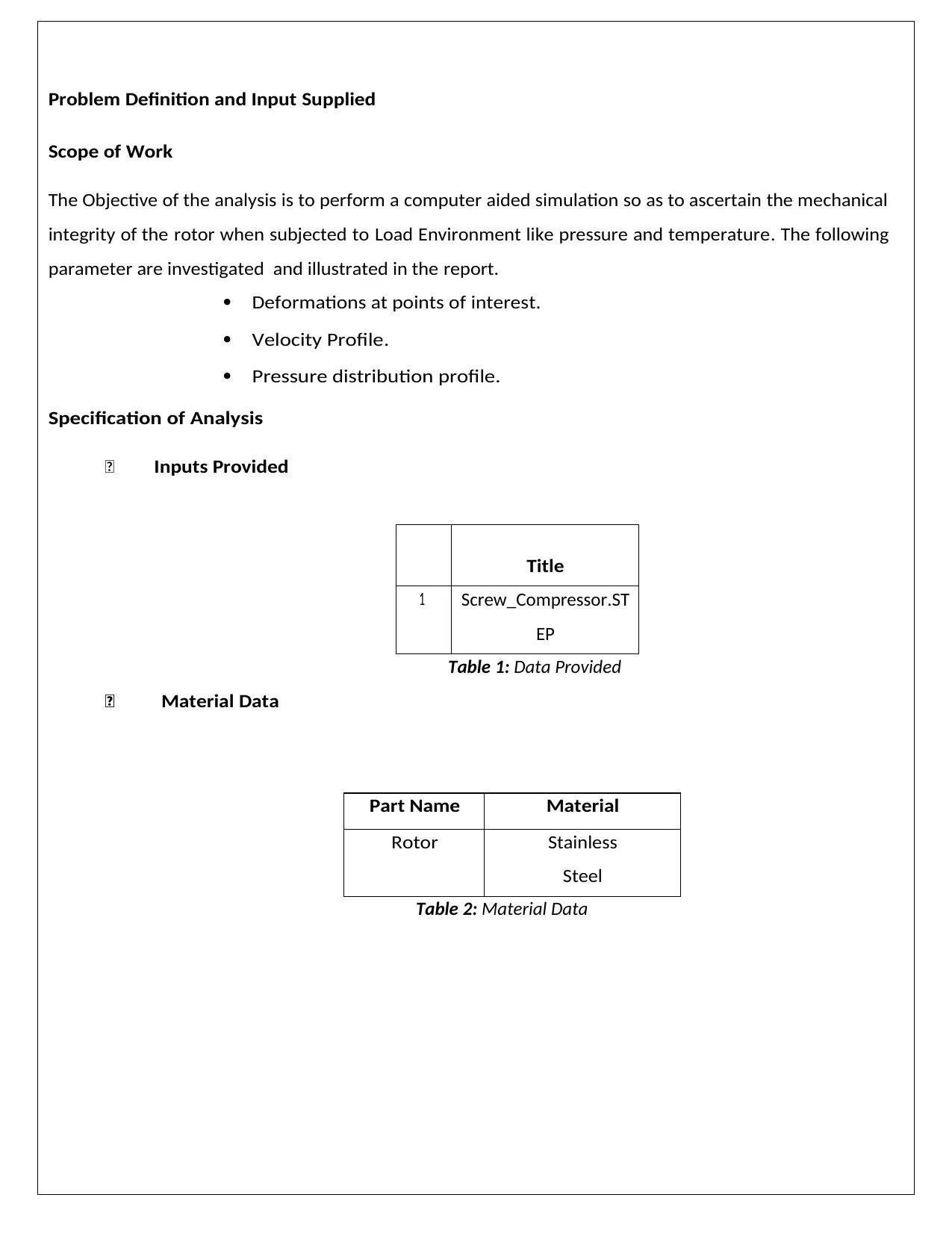
Inputs Provided
Title
1 Screw_Compressor.ST
EP
Material Data
Table 1: Data Provided
Part Name Material
Rotor Stainless
Steel
Table 2: Material Data
Paraphrase This Document
Need a fresh take? Get an instant paraphrase of this document with our AI Paraphraser
Purpose
Rotor is subjected to high pressure and temperature. Also due to rotation of
the rotor dynamic loading is experienced on the rotor. The analysis is to be
carried out to ensure smooth performance and satisfactory functioning in
environment.
Design Check procedures
Selection of stress level, pressure profile and temperature distribution as per the
specification .
Development of Geometric Model of the rotor from the drawings
Deployment of FEM Model
Structural and CFD analysis
Identification of Eigen values
Post processing of response data, Comparison of permissible stress levels vis-à-
vis induced stress levels using various theories of failure.
Scope of the Analysis.
The following types of analysis and load cases are defined and carried out
during FEM Simulation.
Development of FEM Model
Software Used
The computation is performed using the finite element analysis (FEA) program
ANSYS®. The theoretical basis is documented in the ANSYS® THEORETICAL
MANUAL. ANSYS® is developed by ANSYS Inc., Canonsburg Pennsylvania. FEA
Model (FEM) of the refrigeration plant has been constructed and the finite
element model (meshing) has been generated with ANSYS Workbench 15.0
environment. It is then loaded into the workbench environment.
Inputs Used
The Bill of materials was provided and the following material properties
were used during the simulation. The weight as per the drawing is given
in Tables below. The bill of material and material properties of interest
are elucidated in Table 3 and Table 4 respectively.
During the evaluation of the work, we use the standards specified
as a reference point. Material properties are summarized in Table 3.
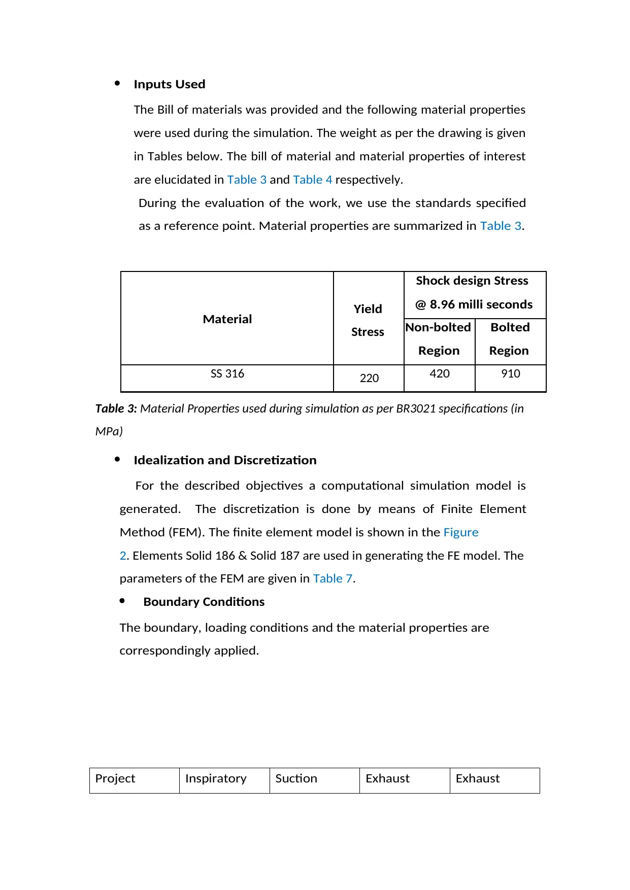
Table 3: Material Properties used during simulation as per BR3021 specifications (in
MPa)
Idealization and Discretization
For the described objectives a computational simulation model is
generated. The discretization is done by means of Finite Element
Method (FEM). The finite element model is shown in the Figure
2. Elements Solid 186 & Solid 187 are used in generating the FE model. The
parameters of the FEM are given in Table 7.
Boundary Conditions
The boundary, loading conditions and the material properties are
correspondingly applied.
Project Inspiratory Suction Exhaust Exhaust
Material Yield
Stress
Shock design Stress
@ 8.96 milli seconds
Non-bolted
Region
Bolted
Region
SS 316 220 420 910
⊘ This is a preview!⊘
Do you want full access?
Subscribe today to unlock all pages.

Trusted by 1+ million students worldwide
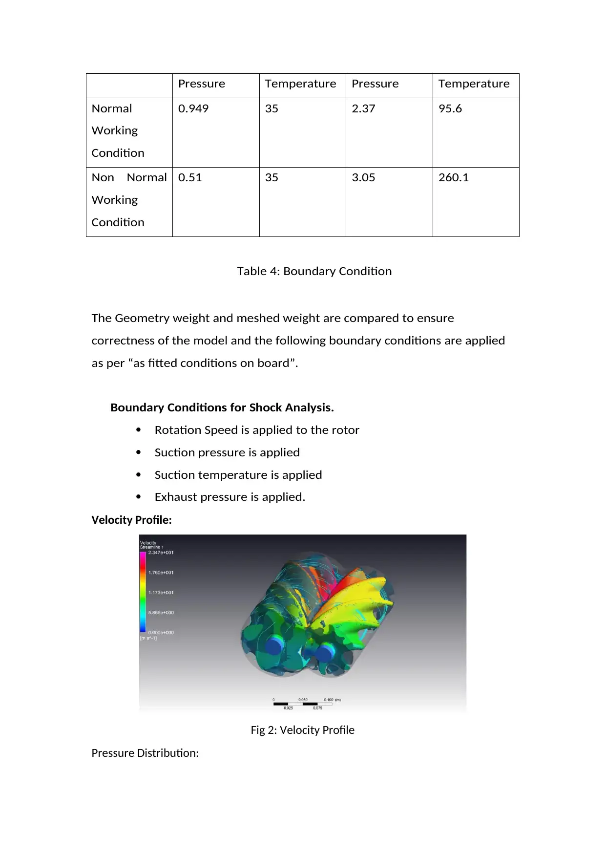
Pressure Temperature Pressure Temperature
Normal
Working
Condition
0.949 35 2.37 95.6
Non Normal
Working
Condition
0.51 35 3.05 260.1
Table 4: Boundary Condition
The Geometry weight and meshed weight are compared to ensure
correctness of the model and the following boundary conditions are applied
as per “as fitted conditions on board”.
Boundary Conditions for Shock Analysis.
Rotation Speed is applied to the rotor
Suction pressure is applied
Suction temperature is applied
Exhaust pressure is applied.
Velocity Profile:
Fig 2: Velocity Profile
Pressure Distribution:
Paraphrase This Document
Need a fresh take? Get an instant paraphrase of this document with our AI Paraphraser
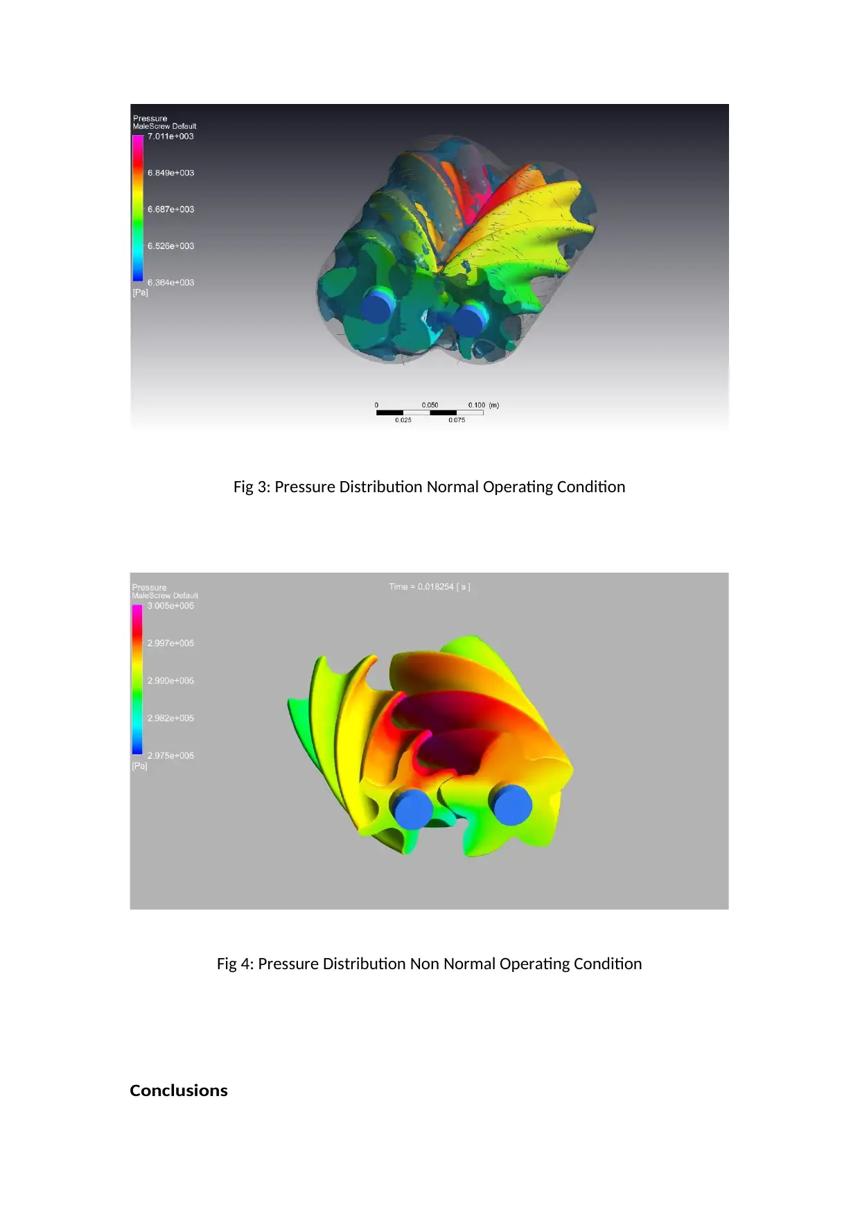
Fig 3: Pressure Distribution Normal Operating Condition
Fig 4: Pressure Distribution Non Normal Operating Condition
Conclusions
Fig 4: Pressure Distribution Non Normal Operating Condition
Conclusions

CFD analysis is done for the rotor, the result shows the exhaust pressure is
2.37 Bar for normal working condition and 3.05 bar for non normal working
condition. Also the velocity distribution is streamline. The stress and
deflection level is under desired level.
We can further optimize the clearance and material as well to increase the
efficiency of the rotor.
Reference:
2.37 Bar for normal working condition and 3.05 bar for non normal working
condition. Also the velocity distribution is streamline. The stress and
deflection level is under desired level.
We can further optimize the clearance and material as well to increase the
efficiency of the rotor.
Reference:
⊘ This is a preview!⊘
Do you want full access?
Subscribe today to unlock all pages.

Trusted by 1+ million students worldwide
1 out of 13
Your All-in-One AI-Powered Toolkit for Academic Success.
+13062052269
info@desklib.com
Available 24*7 on WhatsApp / Email
![[object Object]](/_next/static/media/star-bottom.7253800d.svg)
Unlock your academic potential
Copyright © 2020–2025 A2Z Services. All Rights Reserved. Developed and managed by ZUCOL.