Temperature Control System
VerifiedAdded on 2021/06/17
|8
|1874
|275
AI Summary
Contribute Materials
Your contribution can guide someone’s learning journey. Share your
documents today.
SNO TITLE PAGENO
1. INTRODUCTION 2
2. TEMPERATURE MEASUREMENT 2
3. TEMPERATURE CONTROL SYSTEM 3
4 ON/OFF CONTROLLER 4
5. CONTROL VALVE 4
6. PLC LADDER DIAGRAM 5
7. CONCLUSION 7
REFERENCES 7
1. INTRODUCTION 2
2. TEMPERATURE MEASUREMENT 2
3. TEMPERATURE CONTROL SYSTEM 3
4 ON/OFF CONTROLLER 4
5. CONTROL VALVE 4
6. PLC LADDER DIAGRAM 5
7. CONCLUSION 7
REFERENCES 7
Secure Best Marks with AI Grader
Need help grading? Try our AI Grader for instant feedback on your assignments.
INTRODUCTION:
The purpose of this paper is to design a control system for the annealing furnace. Annealing
furnace is nothing but a furnace that heats up to a maximum temperature and then cools down to
obtain their properties. The alloys are heated up to 860 degree Celsius and then it is cooled for
about 10 hours. The cooling of the furnace is carried out under an argon atmosphere with the
water circulation of about 20 degree Celsius. The on/off control valve provides the supply of the
water. In this paper we have discussed about the temperature measuring device that can be used
in this furnace. This paper also presents the PLC logic diagram for the temperature control
system.
a) TEMPERATURE MEASUREMENT:
Requirement: The temperature in the annealing furnace of about 860 °C with an accuracy of
certain plus or minus of the degree temperature should be measured.
Measuring device: There are several temperature measurement devices that include RTD,
thermistors, thermocouple etc. Out of this thermocouple can be used for this process.
Thermocouple is formed with the two dissimilar metals joined together causes a potential
difference across the junction [1]. This process purely depends on the type of the metal used.
When the temperature across both the junction is same then the potential difference is zero. In
order to get an e.m.f, the difference in the temperature should be produced. Due to this process,
one junction should be kept at 0 °C and the other at a nominal temperature. The potential
produced is given by the formula,
e.m.f= at + bt2 …………………………………………….equation (1)
Where, a and b are constants. There are several types in the thermocouple. Thermocouples with
the base-metal types include E, J, K and T are of lesser cost but they become worse with their
lifespan. Their accuracy varies between ± 1 to 3%. Thermocouple of R type has noble-metal that
are very high in their cost. They have a long lifespan with the accuracy of about ± 1% even better
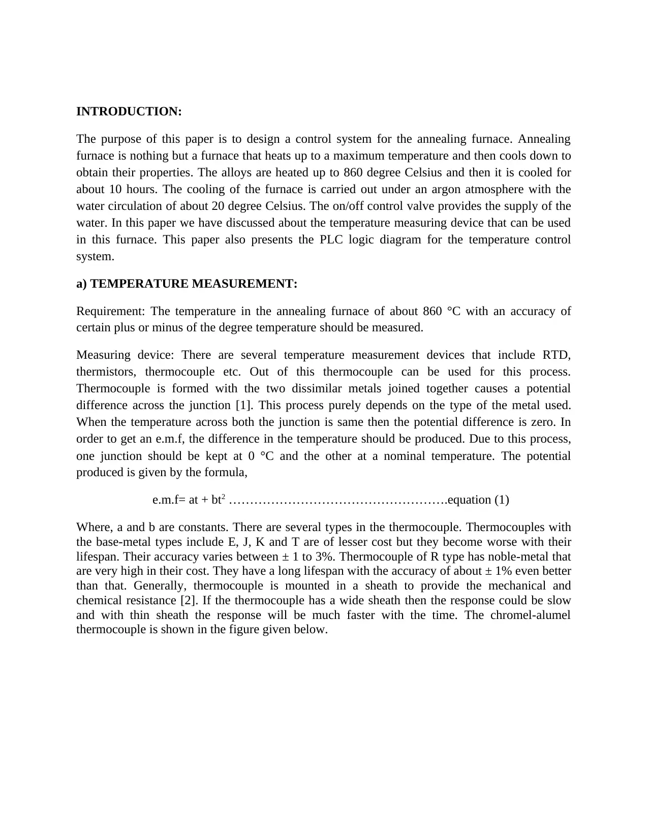
than that. Generally, thermocouple is mounted in a sheath to provide the mechanical and
chemical resistance [2]. If the thermocouple has a wide sheath then the response could be slow
and with thin sheath the response will be much faster with the time. The chromel-alumel
thermocouple is shown in the figure given below.
The purpose of this paper is to design a control system for the annealing furnace. Annealing
furnace is nothing but a furnace that heats up to a maximum temperature and then cools down to
obtain their properties. The alloys are heated up to 860 degree Celsius and then it is cooled for
about 10 hours. The cooling of the furnace is carried out under an argon atmosphere with the
water circulation of about 20 degree Celsius. The on/off control valve provides the supply of the
water. In this paper we have discussed about the temperature measuring device that can be used
in this furnace. This paper also presents the PLC logic diagram for the temperature control
system.
a) TEMPERATURE MEASUREMENT:
Requirement: The temperature in the annealing furnace of about 860 °C with an accuracy of
certain plus or minus of the degree temperature should be measured.
Measuring device: There are several temperature measurement devices that include RTD,
thermistors, thermocouple etc. Out of this thermocouple can be used for this process.
Thermocouple is formed with the two dissimilar metals joined together causes a potential
difference across the junction [1]. This process purely depends on the type of the metal used.
When the temperature across both the junction is same then the potential difference is zero. In
order to get an e.m.f, the difference in the temperature should be produced. Due to this process,
one junction should be kept at 0 °C and the other at a nominal temperature. The potential
produced is given by the formula,
e.m.f= at + bt2 …………………………………………….equation (1)
Where, a and b are constants. There are several types in the thermocouple. Thermocouples with
the base-metal types include E, J, K and T are of lesser cost but they become worse with their
lifespan. Their accuracy varies between ± 1 to 3%. Thermocouple of R type has noble-metal that
are very high in their cost. They have a long lifespan with the accuracy of about ± 1% even better
than that. Generally, thermocouple is mounted in a sheath to provide the mechanical and
chemical resistance [2]. If the thermocouple has a wide sheath then the response could be slow
and with thin sheath the response will be much faster with the time. The chromel-alumel
thermocouple is shown in the figure given below.
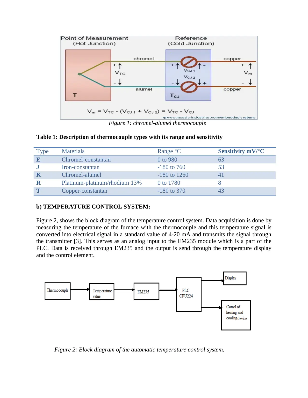
Figure 1: chromel-alumel thermocouple
Table 1: Description of thermocouple types with its range and sensitivity
Type Materials Range °C Sensitivity mV/°C
E Chromel-constantan 0 to 980 63
J Iron-constantan -180 to 760 53
K Chromel-alumel -180 to 1260 41
R Platinum-platinum/rhodium 13% 0 to 1780 8
T Copper-constantan -180 to 370 43
b) TEMPERATURE CONTROL SYSTEM:
Figure 2, shows the block diagram of the temperature control system. Data acquisition is done by
measuring the temperature of the furnace with the thermocouple and this temperature signal is
converted into electrical signal in a standard value of 4-20 mA and transmits the signal through
the transmitter [3]. This serves as an analog input to the EM235 module which is a part of the
PLC. Data is received through EM235 and the output is send through the temperature display
and the control element.
Figure 2: Block diagram of the automatic temperature control system.
In controlling the temperature of the furnace, the on/off controller plays a significant role that
controls the heating and cooling of the furnace. A particular set point should be given in the
operation of the control system [4]. Lower the value than the set point, turns the heater on that
heats the alloy and higher the temperature than the set point turns the heater off.
c) CONTROL VALVE:
For coolant we circulate the water at a flow rate of about 280 litres / min. This is carried out at an
argon atmosphere. This argon gas should be provided from the argon containers at a pressure of
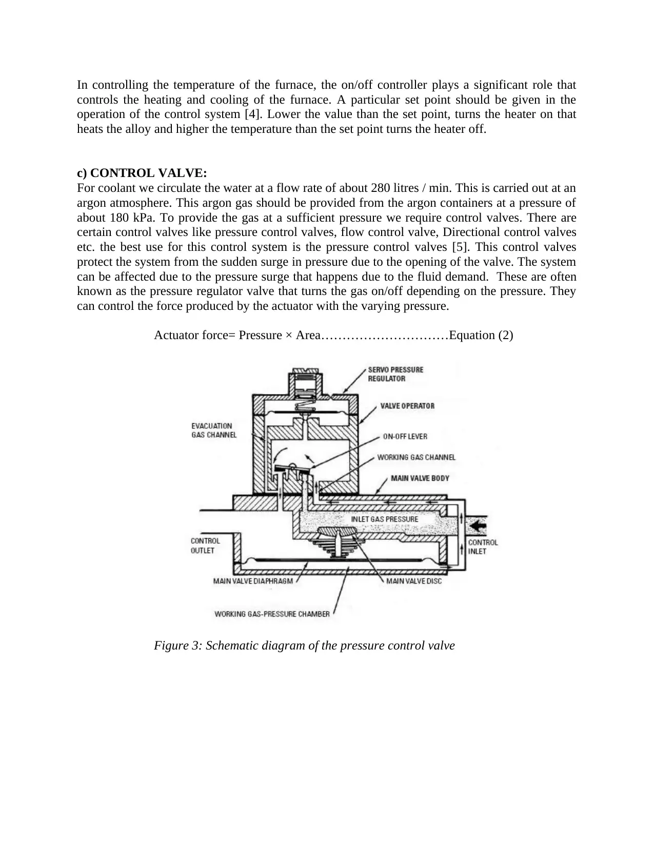
about 180 kPa. To provide the gas at a sufficient pressure we require control valves. There are
certain control valves like pressure control valves, flow control valve, Directional control valves
etc. the best use for this control system is the pressure control valves [5]. This control valves
protect the system from the sudden surge in pressure due to the opening of the valve. The system
can be affected due to the pressure surge that happens due to the fluid demand. These are often
known as the pressure regulator valve that turns the gas on/off depending on the pressure. They
can control the force produced by the actuator with the varying pressure.
Actuator force= Pressure × Area…………………………Equation (2)
Figure 3: Schematic diagram of the pressure control valve
controls the heating and cooling of the furnace. A particular set point should be given in the
operation of the control system [4]. Lower the value than the set point, turns the heater on that
heats the alloy and higher the temperature than the set point turns the heater off.
c) CONTROL VALVE:
For coolant we circulate the water at a flow rate of about 280 litres / min. This is carried out at an
argon atmosphere. This argon gas should be provided from the argon containers at a pressure of
about 180 kPa. To provide the gas at a sufficient pressure we require control valves. There are
certain control valves like pressure control valves, flow control valve, Directional control valves
etc. the best use for this control system is the pressure control valves [5]. This control valves
protect the system from the sudden surge in pressure due to the opening of the valve. The system
can be affected due to the pressure surge that happens due to the fluid demand. These are often
known as the pressure regulator valve that turns the gas on/off depending on the pressure. They
can control the force produced by the actuator with the varying pressure.
Actuator force= Pressure × Area…………………………Equation (2)
Figure 3: Schematic diagram of the pressure control valve
Secure Best Marks with AI Grader
Need help grading? Try our AI Grader for instant feedback on your assignments.
d) PLC Ladder diagram :
A programmable logic controller (PLC) plays a vital role in the field of microprocessor. It’s very
simple and easy for the users to handle since it could consist of hardware and software
components which could handle all the industrial components, and the work of the engineer is to
program the plc using ladder logic which could do certain type of automation and control in the
industrial equipments.
One of the commonly used controllers in the automatic temperature control system is the On/Off
controller. The input value should be compared with the lesser than or equal logic as well as with
the greater than or equal logic. This input value is compared with the set point. The first line of
the ladder logic is connected with the S1 and the last line is connected with heater output which
is responsible for the control of the whole circuit [6]. The MOV instruction addresses the
thermocouple that measures and displays the output of the device. The set point value that is in
the source B is compared with the thermocouple output that is present in the LEQ and GEQ of
source A. These are all present in the same integer file. The set point of LEQ will be a lesser
value and the set point of GEQ will be greater. The ladder diagram works in the following logic:
1) when source A< B in the LEQ logic then the heater turns ON until the output of the low
temperature is true and the output of the high temperature is false [7]. The heater is on till the
high temperature becomes false although low temperature is false.
2) When the high temperature value is reached then Source A will be equal to source B in the
GEQ logic. This will turn off the heater, since the high temperature is true. This is continued till
the low temperature is reached.
This cycle is repeated that helps in maintaining the set point of the furnace [8]. The PLC ladder
diagram is seen in the figure given below.
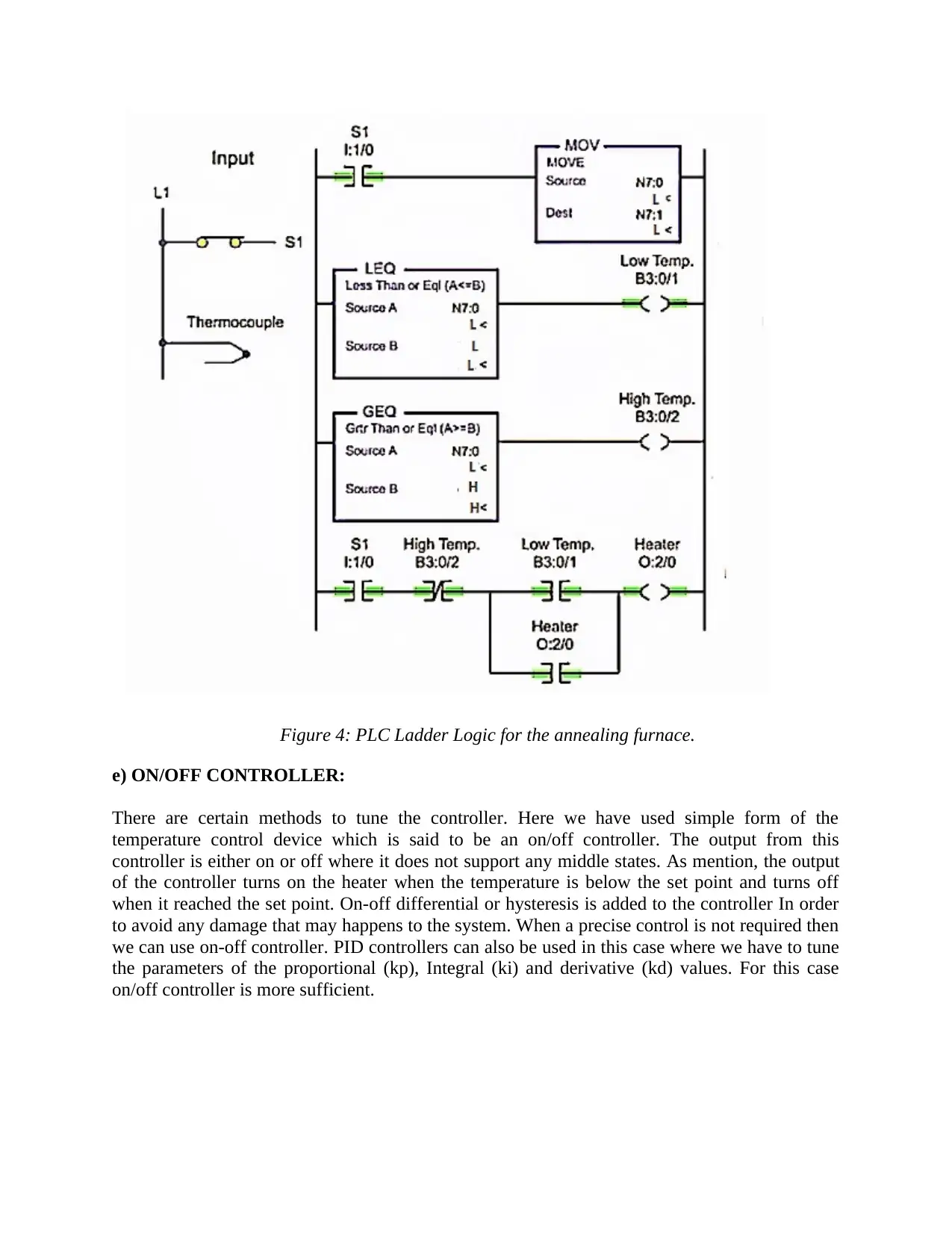
Figure 4: PLC Ladder Logic for the annealing furnace.
e) ON/OFF CONTROLLER:
There are certain methods to tune the controller. Here we have used simple form of the
temperature control device which is said to be an on/off controller. The output from this
controller is either on or off where it does not support any middle states. As mention, the output
of the controller turns on the heater when the temperature is below the set point and turns off
when it reached the set point. On-off differential or hysteresis is added to the controller In order
to avoid any damage that may happens to the system. When a precise control is not required then
we can use on-off controller. PID controllers can also be used in this case where we have to tune
the parameters of the proportional (kp), Integral (ki) and derivative (kd) values. For this case
on/off controller is more sufficient.
f) Mathematical derivation of first order equation:
Given:
RC = 29 min
Rq1 = 1280 k
T0 = 350 k
Equation:
RC dT/dt + T = Rq1 + T0
Hence, 29 dT/dt + T = 1280 + 350
dT/dt + T = 56.207
From the equation, we know dT/dt is the temperature varying with the time and T is the room
temperature.
g) CONCLUSION:
This paper deals with the automatic control system to control the temperature with the control
valve. To optimize the furnace for a better performance the following measures should be carried
out: 1) Tapered return air drop with the proper ductwork setting and the joints should be properly
sealed 2) reduction of turbulence and maintain low pressure drop the throat radius elbow and
turning vanes should be fitted perfectly 3) Choosing suitable filter cabinet with proper quality 4)
dual pipe combustion 5) Proper selection of thermocouple. These following measures could
lower the cost of maintaining the furnace.
REFERENCES:
[1] S. Taylor M.P. Taylor N. Depree, J. Sneyd. Development and validation of models for
annealing furnace control from heat transfer fundamentals. Computers and Chemical
Engineering, 34, 2010.
[2] M. Jelali S. Zareba, A. Wolff. Mathematical modelling and parameter identi- fication of a
stainless steel annealing furnace. Simulation Modelling Practice and Theory, 60, 2016.
[3] F. Lawayeb D. Dumur A. Mouchette X.M. Nguyen, P. Rodriguez-Ayerbe. Temperature
control of reheating furnace based on distributed model predictive control*. 2014. Cited on page
17.
Paraphrase This Document
Need a fresh take? Get an instant paraphrase of this document with our AI Paraphraser
[4] J. Löfberg. Yalmip : A toolbox for modeling and optimization in matlab. In Proceedings of
the CACSD Conference, 2014.
[5] T. Kiefer A. Kugi A. Steinboeck, D. Wild. A mathematical model of a slab reheating furnace
with radiative heat transfer and non-participating gaseous media. International Journal of Heat
and Mass Transfer, 53, 2010.
[6] Curtis D Johnson, “Process Control Instrumentation Technology,” Pearson Education, 2009.
[7] Zhuzhen wang, Xiaodong Zhao, and Haiyan Wang, Design of series leading correction PID
controller,” In the proc. of IEEE International Conference, 2009
[8] Wang Zhenglin, Guo Yangkuan,. Process control engineering and simulation. Beijing:
Electronic Industry Press, 2009.
1 out of 8

Your All-in-One AI-Powered Toolkit for Academic Success.
+13062052269
info@desklib.com
Available 24*7 on WhatsApp / Email
![[object Object]](/_next/static/media/star-bottom.7253800d.svg)
Unlock your academic potential
© 2024 | Zucol Services PVT LTD | All rights reserved.