University Tensile and Hardness Tests on Steel Reinforcing Bars
VerifiedAdded on 2023/05/30
|17
|3384
|64
Practical Assignment
AI Summary
This assignment presents a detailed report on tensile and hardness tests conducted on steel reinforcing bars. The experiment aimed to investigate the mechanical and physical properties of steel under tensile loads and explore the toughness and hardness of carbon steel under different conditions. The report includes a literature review on tensile testing and Charpy impact tests, describing the apparatus used, experimental procedures, and the results obtained. Section A focuses on tensile tests performed on plain and ribbed steel bars, with measurements of cross-sectional area, maximum load, stress, strain, and Young's modulus. Section B examines the toughness and hardness of steel samples subjected to various heat treatments and temperatures, including Charpy impact tests and Vickers hardness measurements. The report analyzes the load-position, load-extension, and stress-strain curves, discussing the elastic and yielding regions, and the relationship between energy absorption and material properties. The analysis includes comparisons of the different samples and treatments, and the results are presented in tables and graphs, offering a comprehensive understanding of the material behavior under different conditions. The findings highlight the impact of factors like carbon content, temperature, and heat treatment on the mechanical properties of steel.
Tensile and Roughness/Hardness Tests 1
TENSILE AND ROUGHNESS/HARDNESS TESTS
Name
Course
Professor
University
City/state
Date
TENSILE AND ROUGHNESS/HARDNESS TESTS
Name
Course
Professor
University
City/state
Date
Paraphrase This Document
Need a fresh take? Get an instant paraphrase of this document with our AI Paraphraser
Tensile and Roughness/Hardness Tests 2
Tensile and Roughness/Hardness Tests
AIM
The aim of the first experiment was to perform tensile tests on steel reinforcing bar
samples and draw load vs. extension graphs so as to compare and cross-examine the physical and
mechanical properties of the steel reinforcing bars. The purpose of the second experiment was to
explore the toughness of carbon steel at low and normal temperatures and the hardness of steel
when exposed to different heat treatments.
INTRODUCTION
Materials behave differently when subjected to tensile loads. Typically, metals extend
when tensile loads are applied on them. The metals continue elongating until they break or
fracture. Tensile test helps in understanding the behaviour of metals under tensile loads
(Michigan Technological University, (n.d.)). This is essential is determining the ability of the
metal to support design loads. Tensile test also provides information about the modulus of
elasticity, yield strength, strain and ultimate tensile strength of the metal (Instron, (n.d.)).
The results of Charpy impact test are affected by factors associated with metal ductility
and toughness. In this test, a typical 10x10mm bar of steel is subjected to sudden impact until it
breaks then the energy absorbed by the bar is measured. The specimen tested is a simply
supported beam. The energy absorbed by the specimen usually depends on temperature. When
temperature is low, the fracture of the carbon steel is brittle hence it absorbs little energy. This
leaves it with a shiny crystalline surface. The impact strength of carbon steel decreases
significantly at low temperature. As temperature increases to high temperature, the fracture
becomes ductile thus ripping the carbon steel sample into spikes making it to absorb significant
Tensile and Roughness/Hardness Tests 3
amount of energy. The factors that affect the hardness and toughness of carbon steel include:
carbon content, temperature and heat treatment.
LITERATURE REVIEW
Tensile test (also referred to as tension test) is a very common test used to investigate the
mechanical and physical properties of steel and other metals. The test is simple (straightforward)
and quite inexpensive (Test Resources, (n.d.)). The test helps in understanding how the metal
reacts and behaves when a tensile load is applied on it. The greater the tension the more the
elongation of the metal. Data obtained from tensile test is used to draw a stress-strain curve. This
curve shows how the metal reacted to the forces that were applied on it.
The ability of materials to resistant loads depends on their properties. There are materials
that are more resistant to static loads but less resistant to sudden loads (impact) and vice versa.
Impact resistance refers to the resistance of a material to sudden load or shock. Charpy impact
test is commonly used for illustrating the effect of temperature on the fracture toughness of steel
and also to establish the resistance of steel specimen towards an impact or a sudden load. The
test determines the amount of energy that a material absorbs when subjected to shock. The test is
very simple and that is one of the reasons why it is commonly used. In Charpy impact test, a
small horizontal beam with a notch is subjected to a sudden load by a large hammer that is fixed
to a pendulum. This loading sequence provides a strain rate that is combined with the notch on
the specimen where a large stress concentration is created enables propagation of fast crack and
fracturing of the specimen.
When a steel specimen is subjected to an impact and it experiences a very little plastic
deformation or forms a small fracture, it is said to be brittle but when it experiences extensive
⊘ This is a preview!⊘
Do you want full access?
Subscribe today to unlock all pages.

Trusted by 1+ million students worldwide
Tensile and Roughness/Hardness Tests 4
plastic deformation or forms a bigger fracture, it is said to be ductile. The surface of a brittle
fracture appears to be clear and shiny whereas the surface of a ductile surface appears to be
fibrous and greyish (Mishra, (n.d.)).
APPARATUS
The apparatus used for tensile tests are Denison Universal Testing Machine, weighing
balance and micrometer. The apparatus used for toughness and hardness test are electric furnace
at 800 °C, chiller fluid, beaker containing cold water to be used for quenching, Charpy impact
apparatus, heat-resistant mat, Vickers hardness apparatus, microscope, eye protection, tongs,
gloves, one steel spanner and four 0.4% carbon steel impact samples (10x10x55mm with
0.25mm tip radius and 2mm deep notch).
PROCEDURE
Section A: Tensile test
Plain bar:
The diameter of the plain bar was measured using the micrometer. This was done by
taking two diameter measurements at different points along the bar’s length. The two measured
diameters of the bar were used to calculate the average cross sectional area of the bar. The
overall length and weight of the bar were also measured and recorded. The average cross
sectional area of the bar was also calculated using density for steel of 7850 kg/m3 and the value
compared with the one that had been determined before.
Ribbed bar:
Paraphrase This Document
Need a fresh take? Get an instant paraphrase of this document with our AI Paraphraser
Tensile and Roughness/Hardness Tests 5
The overall length and weight of the ribbed bar were measured and recorded. The cross
sectional area of the bar was calculated taking density of steel to be 7850 kg/m3.
Tensile tests:
The first sample (plain bar) was secured into the jaws of the Denison Universal Testing
Machine then loaded in tension until it fractured. The load at fracture was recorded as maximum
load. The same process was repeated with the second sample (ripped bar). The tensile testing
software provided two graphs: load vs. position, and load vs. extension.
Section B: Toughness and hardness test
The Charpy Impact Test value of sample A was measured at room temperature without
the sample undergoing any additional treatment from its normalized initial state. Sample B was
heated from its normalized initial state to 800 °C then cooled slowly and its Charpy Impact Test
value measured at room temperature. Sample C was heated from its normalized initial state to
800 °C and then quenched with water and its Charpy Impact Test value measured at room
temperature. The Charpy Impact Test value of sample D was measured at -15 °C without the
sample undergoing any treatment from its normalized initial state. Lastly, the spanner sample
was hardened without additional treatment then its properties observed.
RESULTS
The measured and calculated results from the experiment are as follows:
Section A: tensile testing of steel reinforcing bar
Mild plain bar:
Cross-sectional area = 117.1 mm2
Tensile and Roughness/Hardness Tests 6
Maximum load – 57.25 kN
Stress= Force
Area
Ultimate stress= Maximumload
Area = 57.25 x 10³ N
117.1 mm2 =488.9 N /m m2
Strain at maximum load: = Change∈length , ΔL
Original length , Lo = 0.25 mm
50 mm =0.005
Proportionality limit, E: = Stress
Strain ; this is obtained from the load vs. extension graph
E= F
μ x L
A
Therefore young’s modulus = 34 x 50
0.06926 x 117.1 =209.61 kN /m m2
Ripped bar:
Cross-sectional area = 113.4 mm2
Maximum load – 80.2 kN
Stress= Force
Area
Ultimate stress= Maximumload
Area = 80.2 x 10³ N
113.4 mm2 =707.23 N /mm2
Strain at maximum load: = Change∈length , ΔL
Original length , Lo = 0.30 mm
50 mm =0.006
Proportionality limit, E: = Stress
Strain ; this is obtained from the load vs. extension graph
⊘ This is a preview!⊘
Do you want full access?
Subscribe today to unlock all pages.

Trusted by 1+ million students worldwide
Tensile and Roughness/Hardness Tests 7
E= F
μ x L
A
Therefore young’s modulus = 55 x 50
0.1145 x 113.4 =211.80 kN /mm2
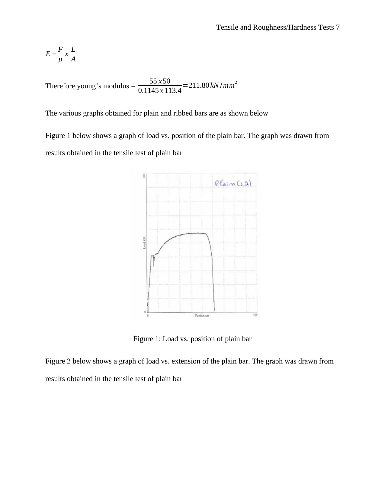
The various graphs obtained for plain and ribbed bars are as shown below
Figure 1 below shows a graph of load vs. position of the plain bar. The graph was drawn from
results obtained in the tensile test of plain bar
Figure 1: Load vs. position of plain bar
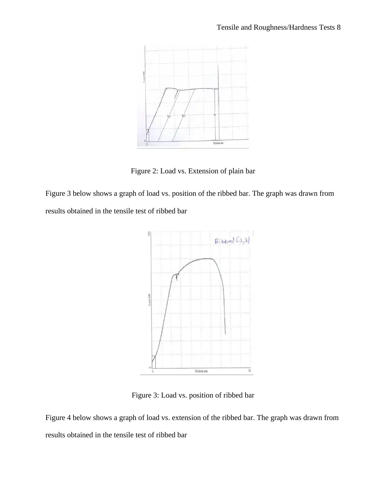
Figure 2 below shows a graph of load vs. extension of the plain bar. The graph was drawn from
results obtained in the tensile test of plain bar
Paraphrase This Document
Need a fresh take? Get an instant paraphrase of this document with our AI Paraphraser
Tensile and Roughness/Hardness Tests 8
Figure 2: Load vs. Extension of plain bar
Figure 3 below shows a graph of load vs. position of the ribbed bar. The graph was drawn from
results obtained in the tensile test of ribbed bar
Figure 3: Load vs. position of ribbed bar
Figure 4 below shows a graph of load vs. extension of the ribbed bar. The graph was drawn from
results obtained in the tensile test of ribbed bar

Tensile and Roughness/Hardness Tests 9
Figure 4: Load vs. extension of ribbed bar
Figure 5: Stress vs. strain of ribbed bar
Figure 4: Load vs. extension of ribbed bar
Figure 5: Stress vs. strain of ribbed bar
⊘ This is a preview!⊘
Do you want full access?
Subscribe today to unlock all pages.

Trusted by 1+ million students worldwide
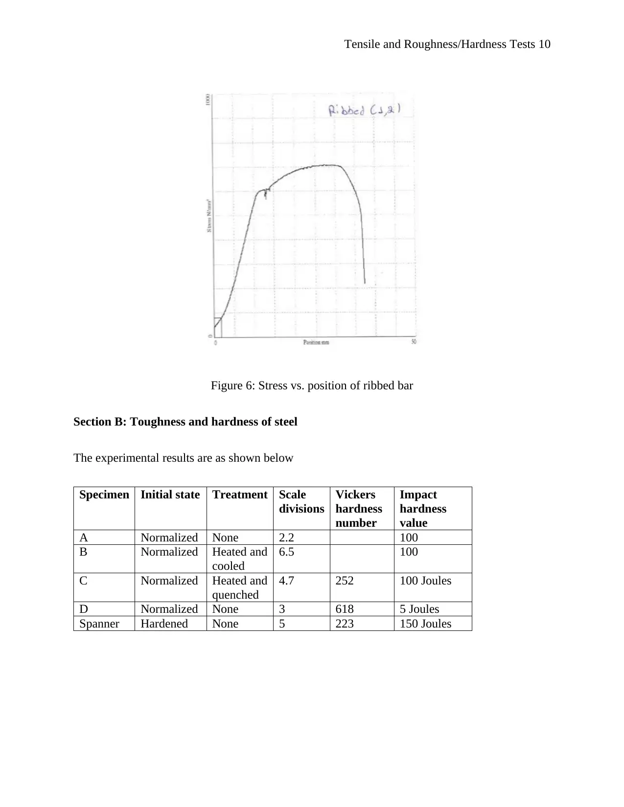
Tensile and Roughness/Hardness Tests 10
Figure 6: Stress vs. position of ribbed bar
Section B: Toughness and hardness of steel
The experimental results are as shown below
Specimen Initial state Treatment Scale
divisions
Vickers
hardness
number
Impact
hardness
value
A Normalized None 2.2 100
B Normalized Heated and
cooled
6.5 100
C Normalized Heated and
quenched
4.7 252 100 Joules
D Normalized None 3 618 5 Joules
Spanner Hardened None 5 223 150 Joules
Paraphrase This Document
Need a fresh take? Get an instant paraphrase of this document with our AI Paraphraser
Tensile and Roughness/Hardness Tests 11
ANALYSIS
The curve in Figure 1 above is similar to a typical load-position curve of a steel bar. The
curve shows that the position of the bar started by increasing proportionally with the increase in
load until reaching elastic limit point. The load increases slightly with increase in position
followed by a gradually decrease in load at constant position. Thereafter, the load increases
gradually with increase in position until maximum load where the bar breaks. The load-position
curve of plain bar and the load-position and stress-position curves of the ribbed bar were similar.
The load vs. position curve of the ribbed bar in Figure 3 above shows the behaviour of
the ribbed bar when tensile load was applied on it. The curve indicates the various stages of the
steel bar the proportional limit, the elastic limit, the yield point, ultimate stress point, and fracture
or breaking point. Proportional limit is the part of the curve where the stress is directly (or
linearly) proportional to strain. The end point of the straight line curve is known as the
proportional limit point or limit of proportionality. The slope of proportional limit line (stress
divided by strain) gives Young’s modulus (BasicMech, 2016). Elastic limit is the region when
the steel bar is perfectly elastic meaning that it can return to its original shape and size if the load
applied on it is removed. The end of the elastic limit is known as the elastic limit point. Once the
material passes the elastic limit point, it starts experiencing plastic deformation, which starts at
yield stress point. Ultimate stress point is the maximum stress that the material can withstand
before starting to break. Beyond the ultimate stress point, the load decreases suddenly with a
small increase in position. Breaking stress (also known as the point of rupture) is the last point of
the curve. This is where the material breaks because it can no longer sustain the stress applied on
it (Afsar, 2014).
Tensile and Roughness/Hardness Tests 12
The load-extension curve of plain bar, load-extension curve of ribbed bar and stress-
strain of the ribbed bar shown in Figures 2, 4 and 5 above are similar to a typical stress-strain
curve of steel. The curve comprises of two main regions: the elastic region and yielding region.
Elastic region is the region where stress is directly proportional to strain while yielding region is
where stress becomes nearly constant with increasing strain. The yield point is where the stress-
strain curve bends abruptly. The area under stress-strain curves in Figure 5 above is equivalent to
the amount of energy absorbed by the metal per unit volume (Instron, 2011). This value is also
referred to as modules of roughness. The higher the amount of energy absorbed by the metal the
tougher and harder the metal is, and vice versa.
The amount of energy absorbed by the specimen during Charpy impact test is determined
by measuring the potential energy at the start and end of the test. Heat treatment hardens steel
samples within a particular temperature range. The toughness of carbon steel was low at low
temperature and increased as the temperature approached normal temperature. This means that
steel should be welded at normal temperature so as to prevent deterioration of its mechanical and
physical properties. When welding steel of low weldability, care should be taken to avoid
exceeding temperature beyond recommended levels. The welder should also wear appropriate
personal protective equipment as a safety precaution.
DISCUSSION
Tensile load influences the behaviour of the metal the load is applied to. The typical
behavior of a steel reinforcing bar when a tensile load is applied on it in increments is that the
bar experiences both elastic and plastic deformations before fracturing. The load-position, load-
extension, stress-strain and stress-position curves are similar because they are plotted using the
same data only that the parameters are different. For instance, stress is obtained from load and
⊘ This is a preview!⊘
Do you want full access?
Subscribe today to unlock all pages.

Trusted by 1+ million students worldwide
1 out of 17
Related Documents
Your All-in-One AI-Powered Toolkit for Academic Success.
+13062052269
info@desklib.com
Available 24*7 on WhatsApp / Email
![[object Object]](/_next/static/media/star-bottom.7253800d.svg)
Unlock your academic potential
Copyright © 2020–2025 A2Z Services. All Rights Reserved. Developed and managed by ZUCOL.


