logo

The Machining Process

11 Pages2130 Words87 Views
   

Added on  2023-01-12

About This Document

This document discusses the machining process, including the analysis of parts and machining parameters. It also covers manufacturing processes, quality control, and sampling acceptance plans.

The Machining Process

   Added on 2023-01-12

ShareRelated Documents
The Machining Process
Name
Institutional Affiliation
1. Analysis of the parts of an air conditioning pipe
The Machining Process_1
Pipe frame (1), an extension pipes between two pipes
Two coaxial holes (2)
Bushings (3)
Top hole covered with a metal sheet (4) attached to (1)
Mounting plate (8)
Sub-assembly composed of (7) and (8) in the frame pipe
Control stick (5)
Control handle (6)
The following components would be manufactured/designed together
Attach the mounting plate and valve together, since they seal the
same hole
Attach control stick, metal tower and handle together, they are on the
same shaft
The bushings can be fixed together in the coaxial holes
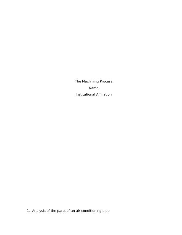
Screen shots of a gas-flow meter are as follows:
Figure 1:The sections of the machine
The Machining Process_2
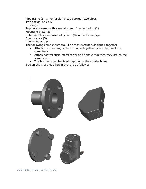
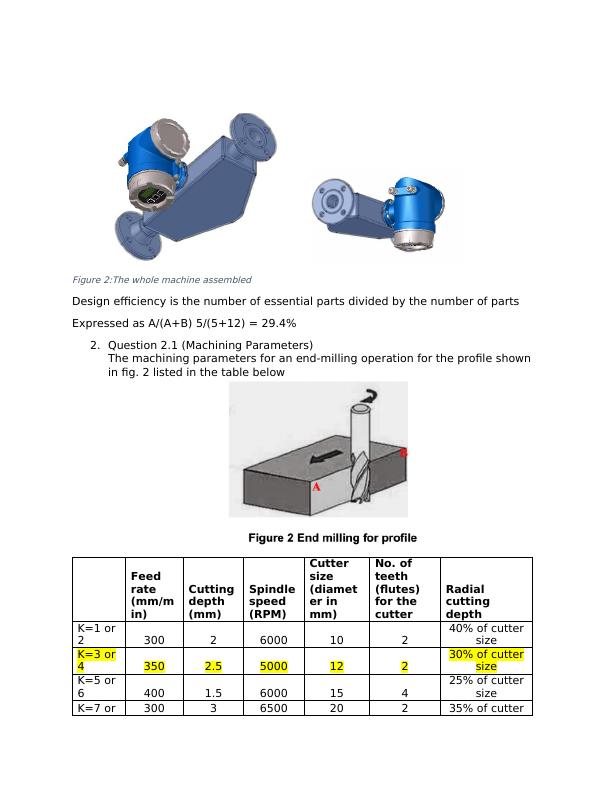
Figure 2:The whole machine assembled
Design efficiency is the number of essential parts divided by the number of parts
Expressed as A/(A+B) 5/(5+12) = 29.4%
2. Question 2.1 (Machining Parameters)
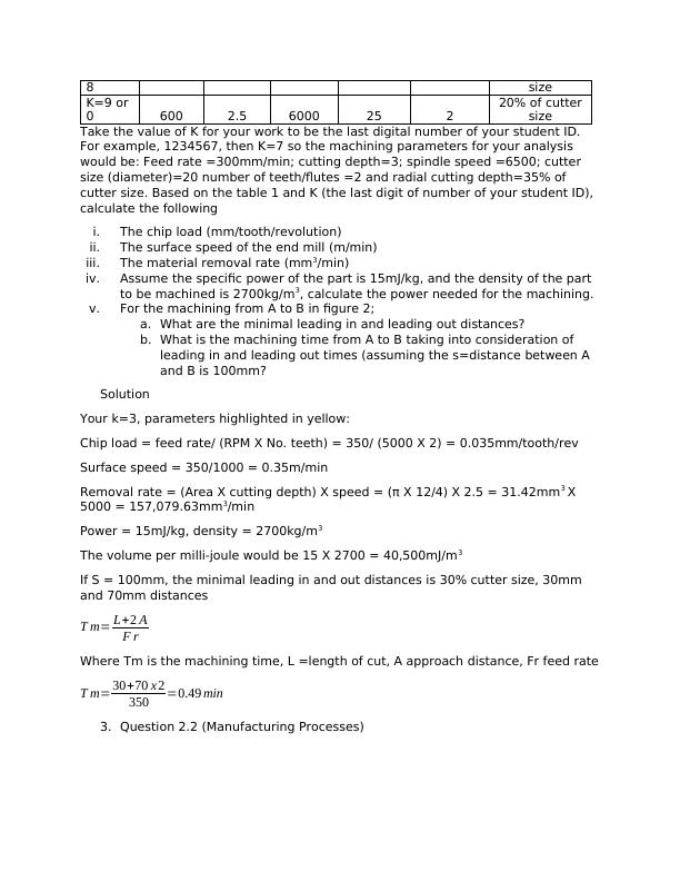
The machining parameters for an end-milling operation for the profile shown
in fig. 2 listed in the table below
Feed
rate
(mm/m
in)
Cutting
depth
(mm)
Spindle
speed
(RPM)
Cutter
size
(diamet
er in
mm)
No. of
teeth
(flutes)
for the
cutter
Radial
cutting
depth
K=1 or
2 300 2 6000 10 2
40% of cutter
size
K=3 or
4 350 2.5 5000 12 2
30% of cutter
size
K=5 or
6 400 1.5 6000 15 4
25% of cutter
size
K=7 or 300 3 6500 20 2 35% of cutter
The Machining Process_3
8 size
K=9 or
0 600 2.5 6000 25 2
20% of cutter
size
Take the value of K for your work to be the last digital number of your student ID.
For example, 1234567, then K=7 so the machining parameters for your analysis
would be: Feed rate =300mm/min; cutting depth=3; spindle speed =6500; cutter
size (diameter)=20 number of teeth/flutes =2 and radial cutting depth=35% of
cutter size. Based on the table 1 and K (the last digit of number of your student ID),
calculate the following
i. The chip load (mm/tooth/revolution)
ii. The surface speed of the end mill (m/min)
iii. The material removal rate (mm3/min)
iv. Assume the specific power of the part is 15mJ/kg, and the density of the part
to be machined is 2700kg/m3, calculate the power needed for the machining.
v. For the machining from A to B in figure 2;
a. What are the minimal leading in and leading out distances?
b. What is the machining time from A to B taking into consideration of
leading in and leading out times (assuming the s=distance between A
and B is 100mm?
Solution
Your k=3, parameters highlighted in yellow:
Chip load = feed rate/ (RPM X No. teeth) = 350/ (5000 X 2) = 0.035mm/tooth/rev
Surface speed = 350/1000 = 0.35m/min
Removal rate = (Area X cutting depth) X speed = (π X 12/4) X 2.5 = 31.42mm3 X
5000 = 157,079.63mm3/min
Power = 15mJ/kg, density = 2700kg/m3
The volume per milli-joule would be 15 X 2700 = 40,500mJ/m3
If S = 100mm, the minimal leading in and out distances is 30% cutter size, 30mm
and 70mm distances
T m= L+2 A
F r
Where Tm is the machining time, L =length of cut, A approach distance, Fr feed rate
T m= 30+70 x 2
350 =0.49 min
3. Question 2.2 (Manufacturing Processes)
The Machining Process_4

End of preview

Want to access all the pages? Upload your documents or become a member.

Related Documents
Design for Assembly - Redesigning AC Control Valve
|19
|1550
|35

Assignment on Research Methodology PDF
|9
|1450
|20