Vidyalankar Institute: Remote Physiological Monitoring CE2 Report
VerifiedAdded on 2020/02/24
|9
|1857
|69
Report
AI Summary
This report details a student's Competency Demonstration (CE2) project focused on remote physiological parameter monitoring, conducted at Vidyalankar Institute of Technology. The project aimed to create a cost-effective system for tracking vital signs, including heart rate and temperature. The student's role involved designing and implementing the hardware module, which utilized an LTH1550-01 photo interrupter sensor and an Arduino board for data acquisition and processing. The report outlines the project's objectives, background, and the student's responsibilities, including hardware design, testing, and documentation. It also highlights the engineering knowledge and skills applied, such as biomedical engineering principles and the use of Arduino APIs. The report addresses challenges encountered, such as data transmission issues and electromagnetic interference, and the solutions implemented. Furthermore, it discusses potential future improvements and collaborative aspects of the project. The project's outcome allows users to monitor their health remotely, providing valuable data for personal health tracking and potential medical applications.
COMPETENCY
DEMONSTRATION REPORT
Career Episode 2
NIDHI SATISH PATIL
DEMONSTRATION REPORT
Career Episode 2
NIDHI SATISH PATIL
Paraphrase This Document
Need a fresh take? Get an instant paraphrase of this document with our AI Paraphraser
CE 2.1 Project Information
Name of the project: Remote Monitoring of Physiological Parameters
Location of the project: Vidyalankar Institute of Technology, Wadala (E), Mumbai
Project Duration: 2013-2014
Organization: Vidyalankar Institute of Technology, Wadala (E), Mumbai
Role and Designation during the time: Team Member
CE 2.2 Project Background
CE 2.2.1 Characteristics of the project
Heart rate is the number of heat beats per unit of time. The number is represented as beats
per minute. The functioning of the heart can vary from person to person. The measurement of the
heart rate is used by the medical professionals to determine the health of the patient. Ups and
downs in the heart rate determines the occurrence of certain diseases in the human body. The
measurement is also followed by athletes who wants to push themselves to the limit to gain
maximum efficiency. The sinusoidal wave which had the R wave to the R wave determines the
inverse of the heart rate.
CE 2.2.2 Objectives developed for the project
The objectives which were set forward for the development of the project are as follows:
To help people to track their health on their own.
To provide periodic reports and alert the individual if there is a change in the heart rate.
To develop a cost effective in nature for accurate monitor of the vital signs.
CE 2.2.3 My area of work
The project was composed of two parts: hardware and corresponding software. For the
project I was in charge of making the hardware module of the device. The main components of
the hardware was to get the reading of the temperature and the heart beat count of the patient. I
was also in charge of testing the product and making the final documentation of the project
which would be eventually be submitted to my university.
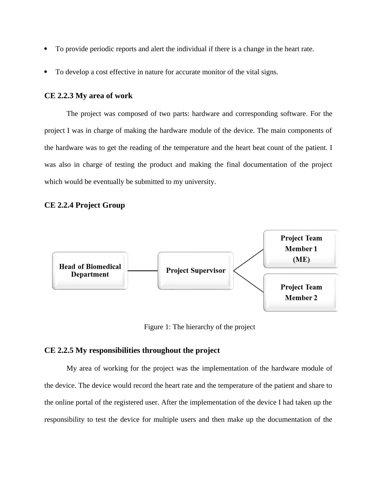
CE 2.2.4 Project Group
Figure 1: The hierarchy of the project
CE 2.2.5 My responsibilities throughout the project
My area of working for the project was the implementation of the hardware module of
the device. The device would record the heart rate and the temperature of the patient and share to
the online portal of the registered user. After the implementation of the device I had taken up the
responsibility to test the device for multiple users and then make up the documentation of the
⊘ This is a preview!⊘
Do you want full access?
Subscribe today to unlock all pages.

Trusted by 1+ million students worldwide
project. The test results were attached to the document to show the working procedure of the
device.
CE 2.3 Distinctive Activity
CE 2.3.1 Comprehending the theory of the project
I proposed the use of a LTH1550-01 is a photo interrupter which forms the
photoplethysmographic sensor for the hardware section. The main working of this portion was to
receive the heart beat count from the finger tips and transmit it to the programming module of
the Arduino. A subsequent portion of the device was the two active working low pass filters
composed of opampLM324. Resistor R23, R17 and capacitor C5 works in setting the gain and
cutting off the frequency of the first filter.
The software part of the device was compiled in Java. The analog output which is
obtained from the heart rate sensor and the thermistor is sent directly to the Arduino board. This
board converts this signal to the equivalent digital output. The following are some of the library
functions which are used by the Arduino.
FreqMeasure.begin(); - Begins the frequency measurement procedure
FreqMeasure.available(); - Returns the number of measurements available to read, or 0 if
no measurements are unread
FreqMeasure.read(); - Read a measurement from the sensors
FreqMeasure.end(); - Stop frequency measurement from the sensors
Paraphrase This Document
Need a fresh take? Get an instant paraphrase of this document with our AI Paraphraser
The library has the following limitations that is when using a multiple software serial
ports, only one of the port can receive data at a time.
The various Arduino functions used are:
analogReference(type) – used to configure the reference voltage which has been used for
analog input
analogRead() – used to read the values from the specified analog pin.
digitalWrite() – used to write high or low values to a digital pin of the Arduino
The following is the Bluetooth APIs of Arduino:
1. BluetoothAdapter - It is used to represents the local Bluetooth adapter. The
BluetoothAdapter is used as an entry for all Bluetooth interaction with the Arduino.
2. BluetoothDevice - It is used to represents a remote Bluetooth device in the project.
This is used as a requesting point for a connection with the remote device through the use of the
BluetoothSocket.
3. BluetoothSocket - It is used to represents the interface that is used as a Bluetooth
socket. This is the point of connection that allows an application to be able to exchange data with
another connected Bluetooth device with the help of InputStream and OutputStream.
4. BluetoothServerSocket - It is used to represents an open socket server which listens for
an incoming requests. In order to produce a connection between two Android devices, one of the
device must contain an open a server socket with the help of this class.
CE 2.3.2 Engineering knowledge and skills applied in the project
The knowledge which was applied for the development of the project pertained to the
domain of Biomedical Engineering. The basic knowledge of the working of different devices
were taught to me during my degree course. Additional information about the working procedure
was collected form the research journals which cleared the knowledge base of the theoretical
approach of the device. Other than this more information was shared to us by our supervisor who
looked after the working of the project.
CE 2.3.3 Accomplishment and task performed
The major portion of the project which was compiled by me was the hardware portion of
the device. I used LTH1550-01 which is a photo interrupter sensor that forms the
photoplethysmographic sensor module in the project. LTH1550-01 is a simple infrared diode
which works as a light transistor receiver pair in a single package. For the next phase of the
circuit I had used of two active working low pass filters composed of opamp LM324. The
LM324 is composed of a quad op amp that can be operated from a mono rail supply. Two
resistors R23, R17 and a capacitor C5 works in setting the gain and cutting off the frequency of
the first filter. The reference voltage of the comparator has been set to a minimum of 0.3V. The
result will be a pulse fluctuating between the values of 0 and 5V at a rate which is equal to the
heart rate.
⊘ This is a preview!⊘
Do you want full access?
Subscribe today to unlock all pages.

Trusted by 1+ million students worldwide
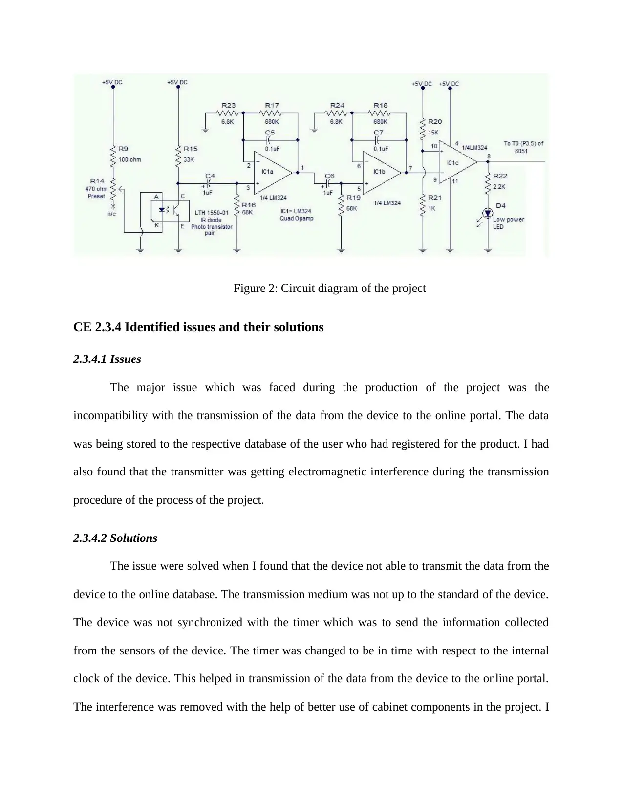
Figure 2: Circuit diagram of the project
CE 2.3.4 Identified issues and their solutions
2.3.4.1 Issues
The major issue which was faced during the production of the project was the
incompatibility with the transmission of the data from the device to the online portal. The data
was being stored to the respective database of the user who had registered for the product. I had
also found that the transmitter was getting electromagnetic interference during the transmission
procedure of the process of the project.
2.3.4.2 Solutions
The issue were solved when I found that the device not able to transmit the data from the
device to the online database. The transmission medium was not up to the standard of the device.
The device was not synchronized with the timer which was to send the information collected
from the sensors of the device. The timer was changed to be in time with respect to the internal
clock of the device. This helped in transmission of the data from the device to the online portal.
The interference was removed with the help of better use of cabinet components in the project. I
Paraphrase This Document
Need a fresh take? Get an instant paraphrase of this document with our AI Paraphraser
had also implemented the use of good ground connection for the whole project to reduce the
Electromagnetic interference of the transmitting signals.
CE 2.3.5 Plan to produce creative and innovative work
If I was provided with more time I would have been able to implement an online database
for each user who has registered in the website for the application. This data base then can be
synchronized with the hospital the user visits with the addition of the doctor’s details and
facilities. Moreover I implemented the project to get the pulse from the wrist of the patient with
the help of a small watch like device. The device can also be implemented in a hospital to
provide real time feedback to the doctors so speed up the procedure.
CE 2.3.6 Collaborative work
I had collaborated with my team mates to produce the project in best quality. I had also
received help from my project supervisor who helped us to understand the main working
procedure of the generally found heart rate monitor. I had also collected research materials on the
topic which was later on explained to us by our supervisor.
CE 2.4 Project Review
CE 2.4.1 Project Overview
The project was completed in a year. The user will be able to track their personal heath
on a regular basis or periodically. The project can also be used to monitor the health o a child or
a senior patient at home from a remote location. The data obtained can be used by the hospitals
to start assessing the emergency situation of the patient as soon as he is brought into the hospital.
CE 2.4.2 My contribution to work
For the project I had taken up the responsibly of making the hardware deice of the device.
This was the main module of the project. I had communicated with the assistant teacher for
getting the project approval. The module would record the temperature and the heart beats of the
patient and send it to the online portal of the connected device. I collaborated with the project
team members before finalizing the plan and the sensors to be used. The user can then view the
statistics of the monitored user in a graphical format. At the end of the project I had conducted
the testing of the device using different users and then documented the working procedure of the
device and the process the device the produced. I had initiated meetings with the assistant teacher
and team members. I had also helped my team mates in their area of work so that the best quality
project can be delivered.
⊘ This is a preview!⊘
Do you want full access?
Subscribe today to unlock all pages.

Trusted by 1+ million students worldwide
1 out of 9
Related Documents
Your All-in-One AI-Powered Toolkit for Academic Success.
+13062052269
info@desklib.com
Available 24*7 on WhatsApp / Email
![[object Object]](/_next/static/media/star-bottom.7253800d.svg)
Unlock your academic potential
Copyright © 2020–2025 A2Z Services. All Rights Reserved. Developed and managed by ZUCOL.


