Cooling Tower Experiment: Introduction, Theory, and Results

Verified

Added on  2023/04/23

|10
|2602
|493
AI Summary
This report gives an introduction of the cooling tower and its operation. The theoretical underpinning of the cooling tower and its construction is discussed. The paper proceeds to discuss the use of the PA Hilton Bench-top Cooling Tower and how it operates while connected to an inclined manometer that measures the pressure.

Contribute Materials

Your contribution can guide someone’s learning journey. Share your documents today.
Document Page
Cooling Tower
Experiment 3
Lead author
(co-Author)

Secure Best Marks with AI Grader

Need help grading? Try our AI Grader for instant feedback on your assignments.
Document Page
ABSTRACT
This report gives an introduction of the cooling tower and its operation. The theoretical
underpinning of the cooling tower and its construction is discussed. The paper proceeds to
discuss the use of the PA Hilton Bench-top Cooling Tower and how it operates while connected
to an inclined manometer that measures the pressure. The mass flow rate is determined at the
onset and heat exchange rate. From the experiment, different temperatures are recorded form the
dry bulb and wet bulb temperatures at the column section of the hygrometer. The reading and
measurements are recorded in different tables in the cooling load as illustrated in the appendix A,
B, and C. Holding all other factors constant, the evaporation rate is linear as the water being
passed through the cooling tower passes through the filler but it stagnates when the air flow rate
attains 100 percent humidity.
TABLE OF CONTENTS
1
Document Page
INTRODUCTION...........................................................................................................................1
Basic Theory................................................................................................................................2
Objectives.....................................................................................................................................3
EXPERIMENTAL METHODS......................................................................................................3
Equipment....................................................................................................................................3
Procedure.....................................................................................................................................4
RESULTS AND DISCUSSION......................................................................................................4
CONCLUSION................................................................................................................................6
REFERENCES................................................................................................................................7
APPENDICES.................................................................................................................................7
INTRODUCTION
A cooling tower is used in cooling liquids stored inside it. The tower is a collection of
equipment which is used to obtain the primary cooling effect from the evaporation of water once
the system is brought into direct contact with air. These towers either implement natural draft or
2
Document Page
mechanical draft. For the natural draft designs, the cooling tower adopts a large concrete
chimney that introduces the air through the media. The mechanical draft is much more prevalent
and the towers utilize large fans that force the air to pass through the circulated water. The water
moves down through the fill surfaces and as a result, it gets to come into contact with air as it
flows down (Baker, Shryock, 2011, p. 339).
The movement enables the heat transfer and ensures that the water drops on the
surrounding air are transferred through latency. The frames are structural forms that support the
casings and any other exterior enclosures for the motors, fans, and other tower components. The
tower is filled with plastic or wood. The fill may be made of splash or film type where the water
falls over the successive layers of the fill while breaking into smaller droplets while wetting the
fill surface and providing the plastic splash so at to promote the heat transfer process.
Many processing industries implement the cooling towers with the aim of eliminating
heat from the operations within the process. The industries, especially, the chemical industries
implement cooling systems. The cooling systems in these industries take away heat from a
process. To reuse the water, the cooling towers are used to cool the water obtained from the
coolants in the processing industries and the water is channeled back to the cooling system. The
iconic cooling towers are domineering skyline towers that enable the removal of heat from the
water. These cooling towers are mainly set up near power stations or chemical or processing
industries (White, 2014, p814). The illustration below captures the Willington Power station
cooling towers located at BerbyShire, UK.
The cooling tower is evaluated on the basis of performance before it is implemented in a
processing industry or plant. It is important to determine the amount of water that can circulate in
the tower on the basis of the capacity utilization metric. The heat is lost by evaporation and the
make-up water is poured into the towers to ensure that there is a total quantity recirculating
around the cooling water system. The tower system is implemented close to processing plants
which use water to cool their heated systems. These processing plants use water to cool as the
abundant, holds a large amount of heat, relatively cheap, high heat of vaporization, high boiling
point, and it is easy to handle water (Broadbent, 2009, p25).
Unfortunately, when dealing with water in the cooling towers, there is microbiological
growth that is quite difficult to control in the system which causes the incubation temperature.
Notably, the tower operates at an incubation temperature of 85-95 degrees and has plenty of
oxygen in its surrounding. There are all the necessary conditions to guarantee the growth of
plants in the tower which may clog the fillers and other porous sections that form part of the
water inlet and outlet. The realization that the microbiological organisms can grow requires
constant cleaning of the system.
Basic Theory
The warm water droplet comes into contact with the air steram and the water evaporates at
a given rate. Th rate of evaporation can be computed based on the vapor pressure at the liquid
top and the matter in the surrounding air. The vapor pressure in the surrounding is based on the
total pressure of the air and the absolute humidity. The tower draws in high volumes of air
through the fillers and splashes which comes into direct contact with the warm water surface and
transfers the heat to the atmosphere around it.
3

Secure Best Marks with AI Grader

Need help grading? Try our AI Grader for instant feedback on your assignments.
Document Page
The air is considered to be saturated at 100 percent humidity. At this point, it cannot
absorb any more water via evaporation. The heat transfer or exchange ensures that the water is
left with less temperature and the air takes up the higher temperature. Within the enclosed tower,
the heat exchange continuously runs until the air and water vapor pressures are equal. An
equilibrium temperature is attained under the adiabatic conditions at the tower surface. There are
two natural draft cooling tower principals namely the wet bulb temperature and the dry bulb
temperature. The dry bulb temperature is the air temperature measured by a regular thermometer
to determine the temperature of the airstream (Landon, D, Hou, 2013).
On the other hand, the lowers temperature arrived at by the wet bulb temperature and
the air moisture. Relating the wet bulb and dry bulb temperature to the cooling tower instance,
the liquid leaving the cooling tower is at the wet bulb temperature of the air streams entering the
system (McBurney, 2010, p20).
Objectives
(i) To determine the mass and energy balances for the different cooling loads in the
cooling tower system at steady state.
(ii) To determine the attributes of a cooling tower based on different loads.
EXPERIMENTAL METHODS
Equipment
(i) PA Hilton Benchtop Cooling Tower
Procedure
(i) Familiarization with the Bench-top cooling tower
(ii) Operation at steady state
(iii) The PA Hilton Bench-top Cooling Tower and the cooling tower was switched on and
the water flow rate was set to 40g/s and heating raised to 0.5kW.
(iv) The air flow rate was adjusted using the damper on the air inlet and the orifice
differential of 10 mm of water using the manometer in 4 minutes.
(v) The temperature was recorded for the different sections of cooling water and
observations were made
(vi) The wet and dry bulb temperatures of the inlet air were measured and compared to
the values of the initial temperatures with the hygrometers to the outlet air.
RESULTS AND DISCUSSION
The experiment was performed to preview the Bench-top cooling tower and it determined
the operation of the system. Several tests were carried out before the actual experiment to test the
operation at steady state (Meitz, 2008, p27). The air flow rate was measured at the pressure
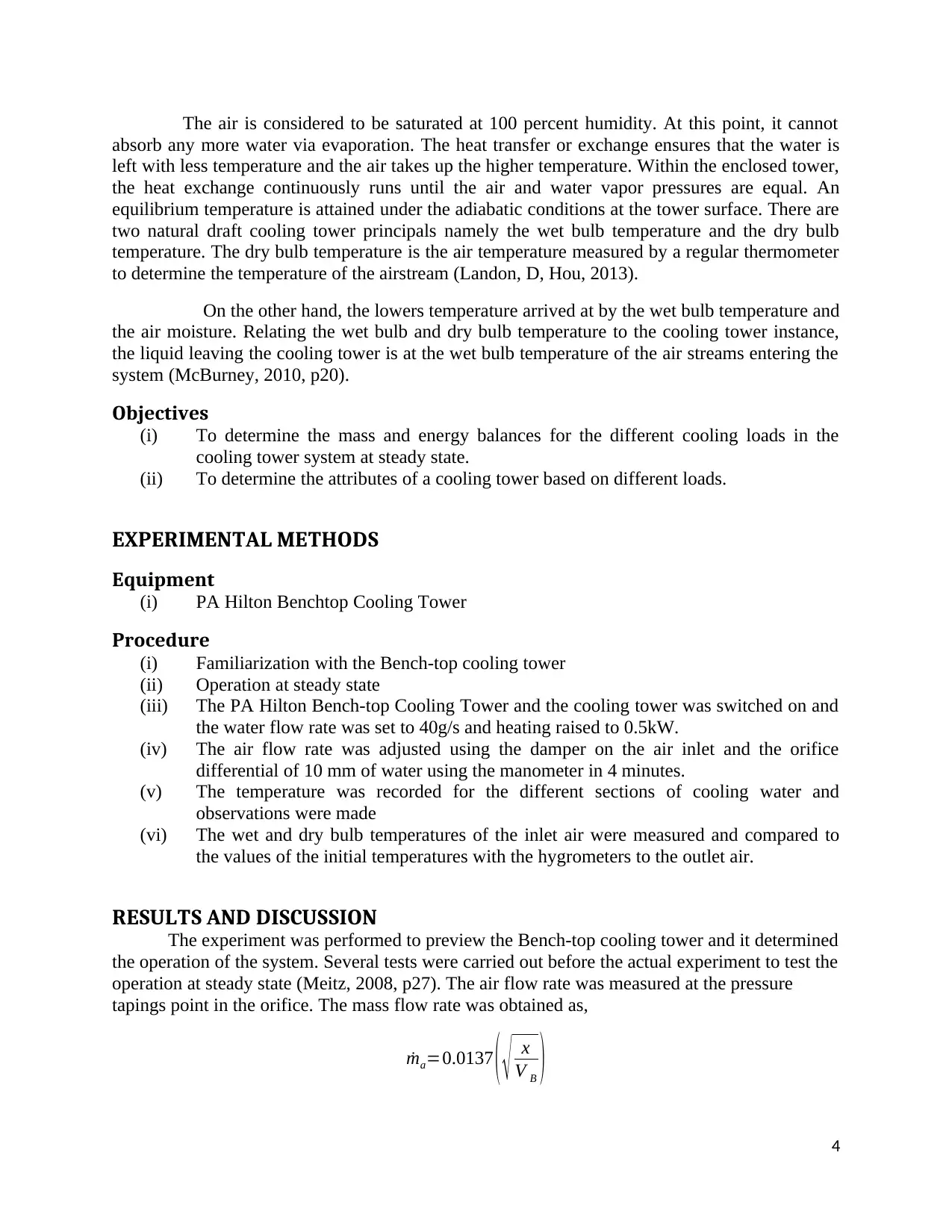
tapings point in the orifice. The mass flow rate was obtained as,
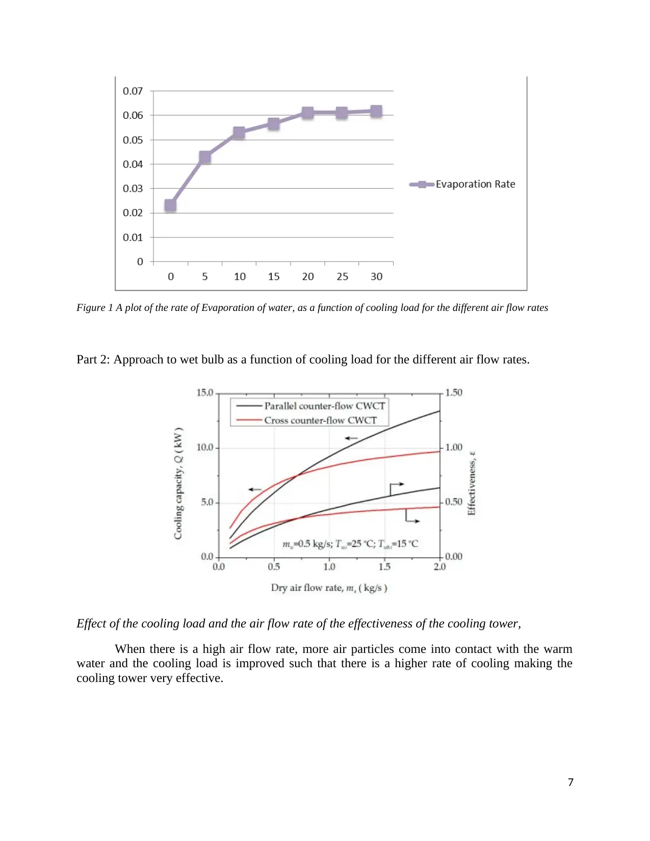
˙ma=0.0137 ( x
V B )
4
Document Page
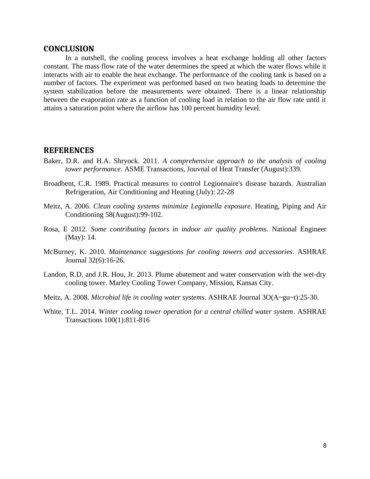
¿ 0.0137 ( x
( 1+ωB ) V aB )
ṁ  a=dry air mass flow rate(kg s 1)
x=orifice differential ( mm H 2 O)
vB=specific volume of vapourair mixture leaving top of column(m 3 kg 1)
vaB=specific volume of dry air leaving top of column(m3 kg 1)
wB =humidity of air leaving thetop of thecolumnPoint BFigure 2.4 (kg kg 1)
vB , vaBwB
The values depend on the wet and dry bulb temperatures and are obtained from a
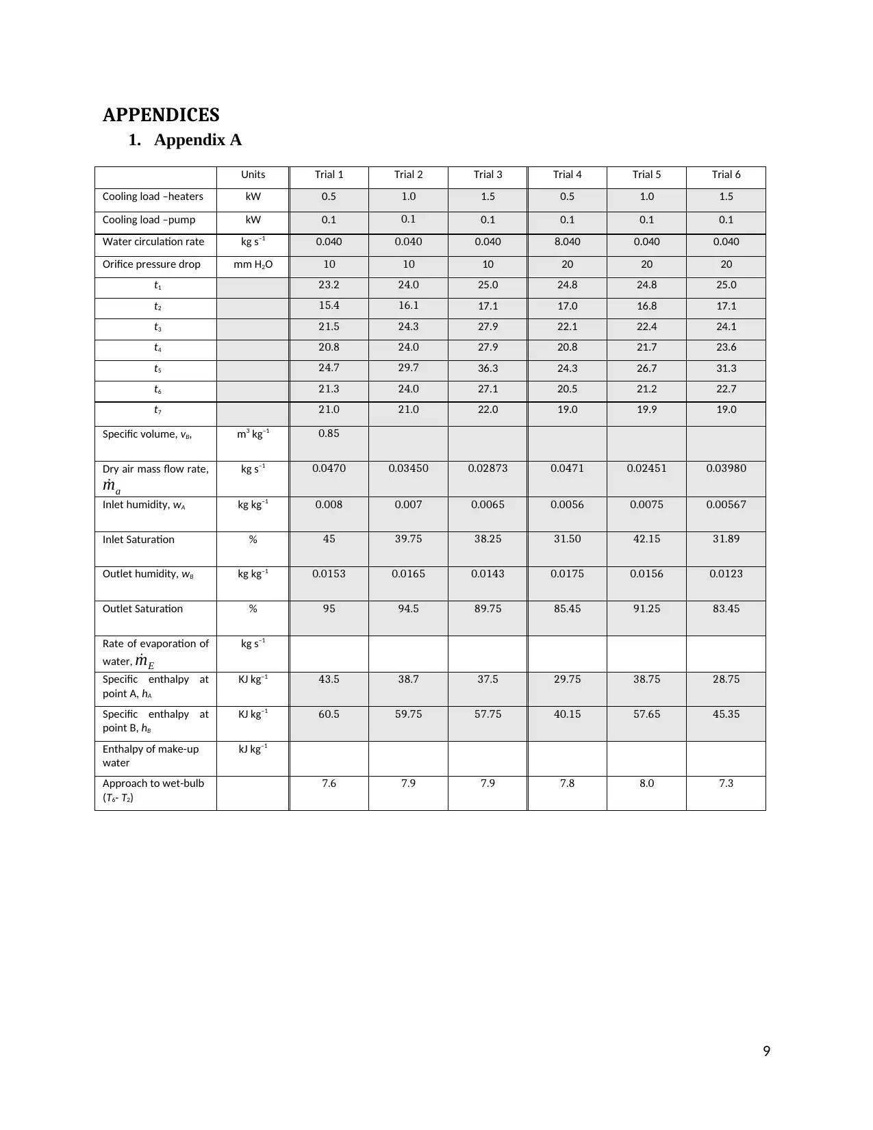
psychrometric chart. The table with the results is recorded in the table in Appendix A, B, and C.
the mass balances at the cooling tower are based on the air entering and leaving the tower.
˙mE = ˙mstreamB ˙mstreamA
¿ ˙ma ( ωBωA )
The difference between the energy flow rates at the inlet and outlet orifices is equal to the
overall balance of energy such that the water pumps energy and the load supplied by the heaters.
The energy content is expressed as,
¿ ˙Q+P= ˙H out ˙H¿
˙H A = ˙ma hA
At point E, the enthalpy of water is given as,
˙Q+ P= ˙ma hB ˙ma hA ˙mE hE = ˙ma ( hB hA ) ˙mE hE
The range computes the difference between the cooling tower water inlet and outlet
temperature. The higher the cooling tower range the better the performance for the cooling
tower. The approach is the difference between the cooling tower outlet cold water temperature
and ambient wet bulb temperature. The cooling tower effectiveness can, therefore, be determined
as a percentage ratio of the measured range and the ideal range. The water quantity evaporated
based on the cooling duty refers to the evaporation loss while the cooling capacity focuses on the
mass flow rate of water, specific heat, and temperature difference. The blow-down losses are
obtained based on the cycles of concentration and evaporation losses.
C T range=C W inlettemp C W outlettemp
C T approach=C W outlettempW Btemp
5
Document Page
C T effectiveness=100C W tempC W outtemp
C W intemp W Btemp
Evaporatio nloss=0.000851.8circulatio nrate( T 1T 2 )
Blo wdown= Evaporatio nl oss
cycle sconcentration1
The liquid-gas ratio is given as,
L ( T1T2 ) =G ( h2h1 )
L
G = h2h1
T 1T 2
To obtain the value of Vb and Vab and the wet bulb value,
V B = 0.01372x2
˙ma
2 =0.00018769 x2
˙ma
V B =0.00018769( 102
40 )=0.000469225
V a B=0.01372
( x
1+ωB ˙ma )
V aB =0.00018769( 10
1+ 0.015340 )=0.00116433
V aB =1.16433103
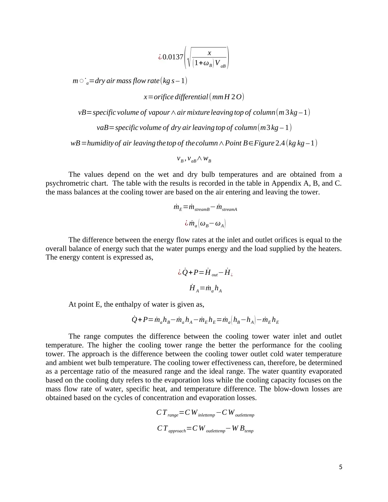
The rate of evaporation of water and the enthalpy of make-up water is computed and
determined alongside the approach to wet bulb value. The overall energy balance value is
computed and recorded in the table as shown in Appendix A. The rate of evaporation of water is
given as a function of cooling load for the different air flow rates.
Part 1: rate of Evaporation of water against cooling load for different air flow rates
6

Paraphrase This Document

Need a fresh take? Get an instant paraphrase of this document with our AI Paraphraser
Document Page
Figure 1 A plot of the rate of Evaporation of water, as a function of cooling load for the different air flow rates
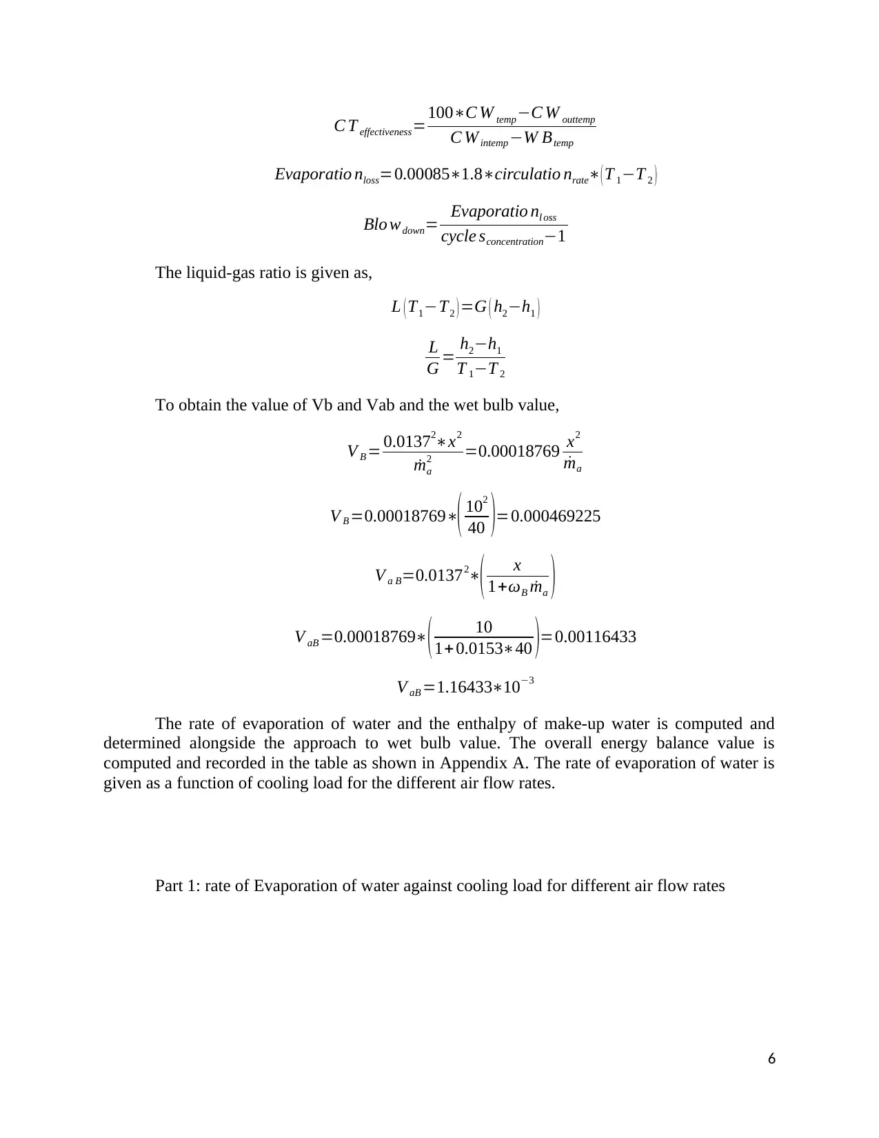
Part 2: Approach to wet bulb as a function of cooling load for the different air flow rates.
Effect of the cooling load and the air flow rate of the effectiveness of the cooling tower,
When there is a high air flow rate, more air particles come into contact with the warm
water and the cooling load is improved such that there is a higher rate of cooling making the
cooling tower very effective.
7
Document Page
CONCLUSION
In a nutshell, the cooling process involves a heat exchange holding all other factors
constant. The mass flow rate of the water determines the speed at which the water flows while it
interacts with air to enable the heat exchange. The performance of the cooling tank is based on a
number of factors. The experiment was performed based on two heating loads to determine the
system stabilization before the measurements were obtained. There is a linear relationship
between the evaporation rate as a function of cooling load in relation to the air flow rate until it
attains a saturation point where the airflow has 100 percent humidity level.
REFERENCES
Baker, D.R. and H.A. Shryock. 2011. A comprehensive approach to the analysis of cooling
tower performance. ASME Transactions, Jouvnal of Heat Transfer (August):339.
Broadbent, C.R. 1989. Practical measures to control Legionnaire's disease hazards. Australian
Refrigeration, Air Conditioning and Heating (July): 22-28
Meitz, A. 2006. Clean cooling systems minimize Legionella exposure. Heating, Piping and Air
Conditioning 58(August):99-102.
Rosa, E 2012. Some contributing factors in indoor air quality problems. National Engineer
(May): 14.
McBurney, K. 2010. Maintenance suggestions for cooling towers and accessories. ASHRAE
Journal 32(6):16-26.
Landon, R.D. and J.R. Hou, Jr. 2013. Plume abatement and water conservation with the wet-dry
cooling tower. Marley Cooling Tower Company, Mission, Kansas City.
Meitz, A. 2008. Microbial life in cooling water systems. ASHRAE Journal 3O(A~gu~t):25-30.
White, T.L. 2014. Winter cooling tower operation for a central chilled water system. ASHRAE
Transactions 100(1):811-816
8
Document Page
APPENDICES
1. Appendix A
Units Trial 1 Trial 2 Trial 3 Trial 4 Trial 5 Trial 6
Cooling load –heaters kW 0.5 1.0 1.5 0.5 1.0 1.5
Cooling load –pump kW 0.1 0.1 0.1 0.1 0.1 0.1
Water circulation rate kg s–1 0.040 0.040 0.040 8.040 0.040 0.040
Orifice pressure drop mm H2O 10 10 10 20 20 20
t1 23.2 24.0 25.0 24.8 24.8 25.0
t2 15.4 16.1 17.1 17.0 16.8 17.1
t3 21.5 24.3 27.9 22.1 22.4 24.1
t4 20.8 24.0 27.9 20.8 21.7 23.6
t5 24.7 29.7 36.3 24.3 26.7 31.3
t6 21.3 24.0 27.1 20.5 21.2 22.7
t7 21.0 21.0 22.0 19.0 19.9 19.0
Specific volume, vB, m3 kg–1 0.85
Dry air mass flow rate,
˙ma
kg s–1 0.0470 0.03450 0.02873 0.0471 0.02451 0.03980
Inlet humidity, wA kg kg–1 0.008 0.007 0.0065 0.0056 0.0075 0.00567
Inlet Saturation % 45 39.75 38.25 31.50 42.15 31.89
Outlet humidity, wB kg kg–1 0.0153 0.0165 0.0143 0.0175 0.0156 0.0123
Outlet Saturation % 95 94.5 89.75 85.45 91.25 83.45
Rate of evaporation of
water, ˙mE
kg s–1
Specific enthalpy at
point A, hA
KJ kg–1 43.5 38.7 37.5 29.75 38.75 28.75
Specific enthalpy at
point B, hB
KJ kg–1 60.5 59.75 57.75 40.15 57.65 45.35
Enthalpy of make-up
water
kJ kg–1
Approach to wet-bulb
(T6- T2)
7.6 7.9 7.9 7.8 8.0 7.3
9
1 out of 10
circle_padding
hide_on_mobile
zoom_out_icon
[object Object]

Your All-in-One AI-Powered Toolkit for Academic Success.

Available 24*7 on WhatsApp / Email

[object Object]