Competency Demonstration Report for Antenna Design
VerifiedAdded on 2020/02/24
|9
|1742
|37
Report
AI Summary
This report details the development of a low RCS microstrip patch antenna using complementary split-ring resonators. It outlines the project background, objectives, methodologies, and results achieved during the design and simulation phases. The report emphasizes the importance of reducing radar cross-section (RCS) for enhancing the performance of antennas used in military applications. It also discusses the collaborative efforts in the project and the innovative solutions implemented to overcome technical challenges.
Competency Demonstration Report (CDR)
Career Episode 2
Sainath Punukollu
Career Episode 2
Sainath Punukollu
Paraphrase This Document
Need a fresh take? Get an instant paraphrase of this document with our AI Paraphraser
CE 2.1: Project Introduction
Name of the Project : Development of Low RCS Microstrip Patch Antenna
Using Complementary Split-Ring Resonators
Geographical Location :[Please Fill]
Project Duration : [Please Fill]
Organization : [Please Fill]
Position in the Project : Team Member
CE 2.2: Project Background
CE 2.2.1: Characteristics of the Project
In modern military vehicles, helicopters, missiles, and aircraft, the RCS (radar cross
section) is considered as a vital element impacting the performance and efficiency of the
antenna. I have observed that it is essential to reduce the RCS component for preserve the
observable nature of modern vehicles. Therefore, in this particular project I have focused on
reducing the PCS component for the micro strip antenna. I have used complementary split ring
resonator (CSRR) with the proposed antenna for accomplishing he reduced RCS. I have used
11.15 GHz of frequency for developing the appropriate design and simulation for the process.
Therefore in this project, I have planned on developing the appropriate new advanced design of a
micro strip antenna while increasing the operational efficiency and reducing the RCS.
Page 1 of 9
CE 2.2.2: Objectives developed for project
While working on this project, I have observed that various techniques for RCS
reductions are existence at present. But, the application of those techniques in the air borne
vehicles creates significant hurdles and operational difficulties. Therefore, in this project, I have
worked for reducing the RCS effect without negatively impacting the efficiency and operational
functionality of the micro strip antenna. Therefore, for completing the project, I have developed
the appropriate objectives:
To identify the current process and techniques used for reducing the RCS;
To propose an enhanced antenna design for the project;
To fabricate and simulate the micro strip antenna for RCS reduction;
To implement the technique of CSRR in the antenna design;
To simulate the developed antenna design and ensuring the efficiency and proper
operation of the proposed micro strip antenna;
CE 2.2.3: My area of work
I have demonstrated and fabricated the placement of the split-ring component in the
micro strip antenna. In addition to that, I have identified and ensured the application of proper
capacitance and inductance in the antenna design and identified the different parameter for the
implementation of the micro strip antenna. In addition to that, I have considered 11 GHz of
frequency for design and simulation of the antenna deign.
Page 2 of 9
⊘ This is a preview!⊘
Do you want full access?
Subscribe today to unlock all pages.

Trusted by 1+ million students worldwide
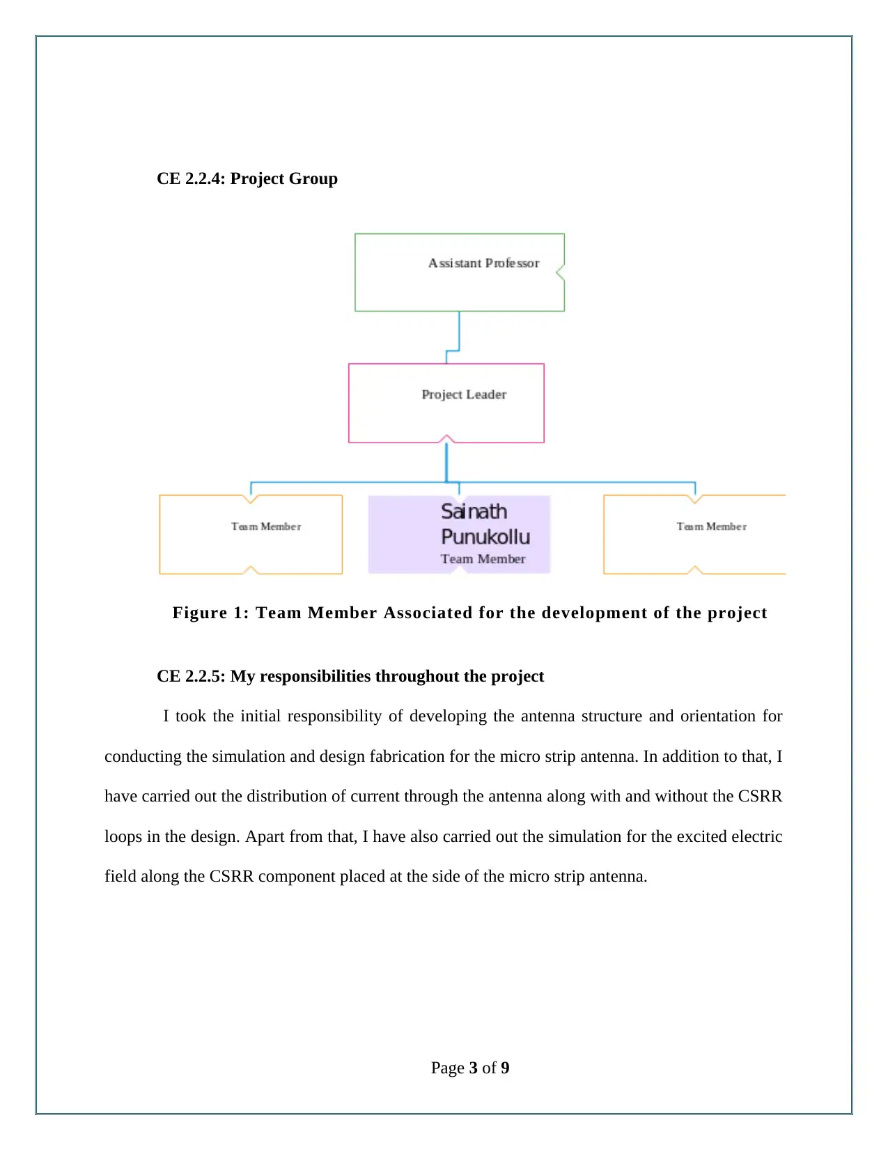
CE 2.2.4: Project Group
Figure 1: Team Member Associated for the development of the project
CE 2.2.5: My responsibilities throughout the project
I took the initial responsibility of developing the antenna structure and orientation for
conducting the simulation and design fabrication for the micro strip antenna. In addition to that, I
have carried out the distribution of current through the antenna along with and without the CSRR
loops in the design. Apart from that, I have also carried out the simulation for the excited electric
field along the CSRR component placed at the side of the micro strip antenna.
Page 3 of 9
Paraphrase This Document
Need a fresh take? Get an instant paraphrase of this document with our AI Paraphraser
CE 2.3: Distinctive Activity
CE 2.3.1: Comprehending the Theory of the project
In this project, I have focused on developing the antenna using the reduction technique of
RCS (Radar Cross Section). I have aimed at illustrating and applying the concept of CSRR
(Complementary split-ring resonator) while developing the design of the micro strip antenna.
Through this project I have aimed at replacing the ground plane of the microstrip antenna with
the appropriate CSRR element. The spatial filters used in electromagnetic waves in the split ring
resonators, has been utilized for reducing the RCS and improving the performance of the
antenna. Therefore, in this project, high pass filter, low pass filter, CSRR and SRR are
implemented for the design of the micro strip antenna.
CE 2.3.2: Engineering Knowledge and Skills applied in the project
Before developing the appropriate design of the antenna, I have studied the particular
design and past studies that have been carried out in the field of micro strip antenna. From the
analysis, I have observed that in the miniature antenna, CSRR materials and RSC reduction
techniques are widely used. In this project, during the design of the antenna, I have etched the
loops or rings with the ground plane below the SCRR strip conductor used in the antenna. I have
implemented the conductor in parallel to the resonant tank LC circuit for matching the resonant
frequency. For evaluating the particular resonant frequency of the antenna, I have utilized the
following equation:
F = 1 / (2π Leq Ceq)
Page 4 of 9
In the above equation, I have used F for denoting the resonant frequency, Leq and Ceq for
demonstrate the inductance and capacitance properties of the CSRR component that I have used
during the antenna design. Furthermore, I have reduced the traditional SCRR for realizing the
impact of the RCS over the antenna performance. In this project, I have kept the resonant
frequency to 11 GHz for design and simulation of the antenna.
CE 2.3.3: Accomplishment and Task Performed
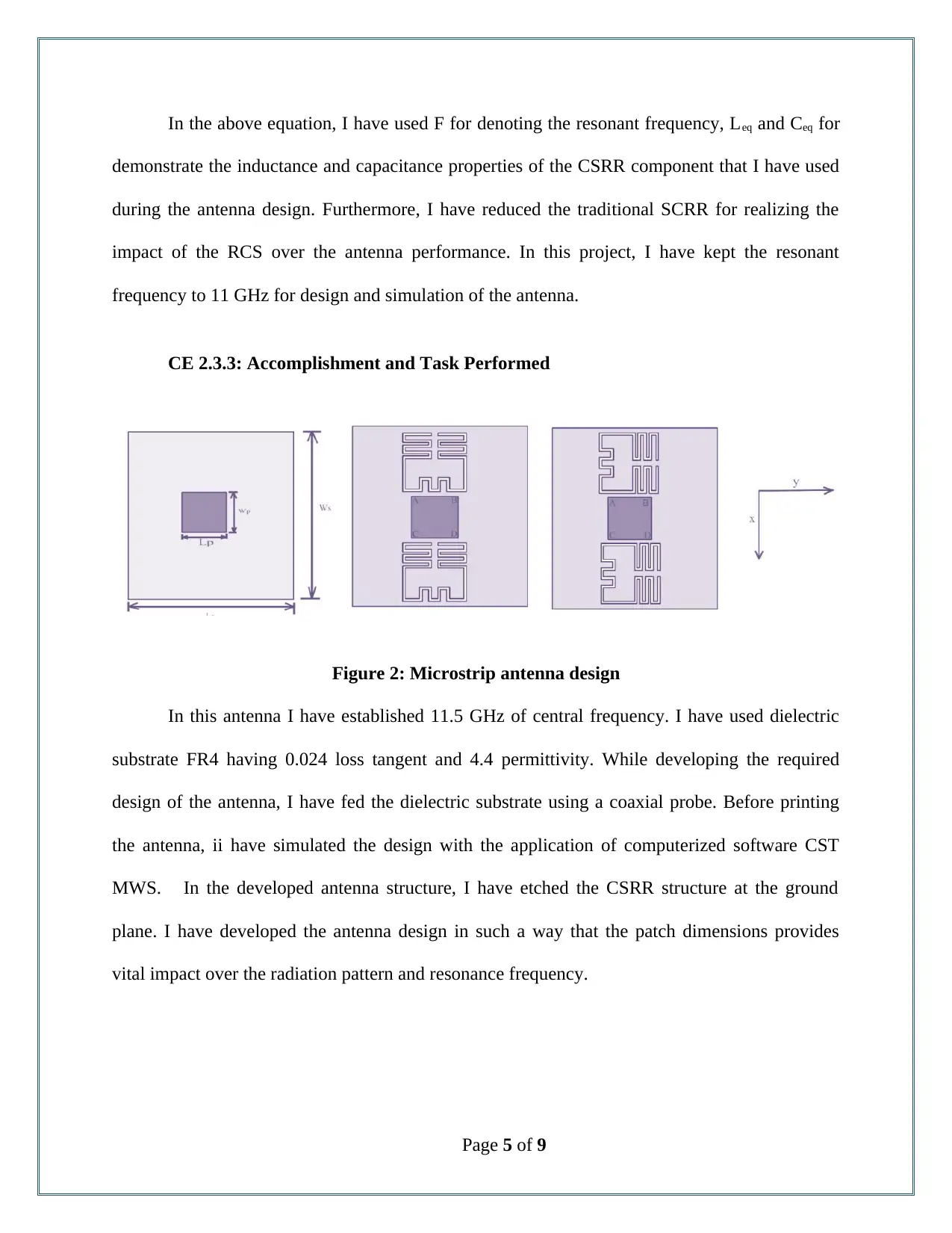
Figure 2: Microstrip antenna design
In this antenna I have established 11.5 GHz of central frequency. I have used dielectric
substrate FR4 having 0.024 loss tangent and 4.4 permittivity. While developing the required
design of the antenna, I have fed the dielectric substrate using a coaxial probe. Before printing
the antenna, ii have simulated the design with the application of computerized software CST
MWS. In the developed antenna structure, I have etched the CSRR structure at the ground
plane. I have developed the antenna design in such a way that the patch dimensions provides
vital impact over the radiation pattern and resonance frequency.
Page 5 of 9
⊘ This is a preview!⊘
Do you want full access?
Subscribe today to unlock all pages.

Trusted by 1+ million students worldwide
CE 2.3.4: Identified Issues and Their Solutions
Issue: In this project, I have tried to determine the effect of the antenna dimension over
the radiation pattern and the resonance frequency of the antenna. I have printed the antenna
structure and used microwave studio simulation technology (CST MWS) for simulating the
performance and operation of the antenna. I have faced significant technical issue during the
simulation process after attaching the CSRR component at each side of the antenna. From the
initial simulation I have observed significant disruption in the signal with the placement of the
CSRR components.
Solution: For overcoming with the issue, I have communicated the issue ad design with
my team member who was working alongside me for the design of the antenna. From the
analysis I have observed that the placement of the CSRR component at each side of the antenna
is not completely parallel to the antenna that has resulted in the disruption of the signals. After
this, I have etched the antenna with parallel orientation with the antenna along both the x and y
axis. I have further simulated the antenna in three different conditions and found almost no
disruption of the signals.
Page 6 of 9
Paraphrase This Document
Need a fresh take? Get an instant paraphrase of this document with our AI Paraphraser
CE 2.3.5: Plan for producing creative and innovative work
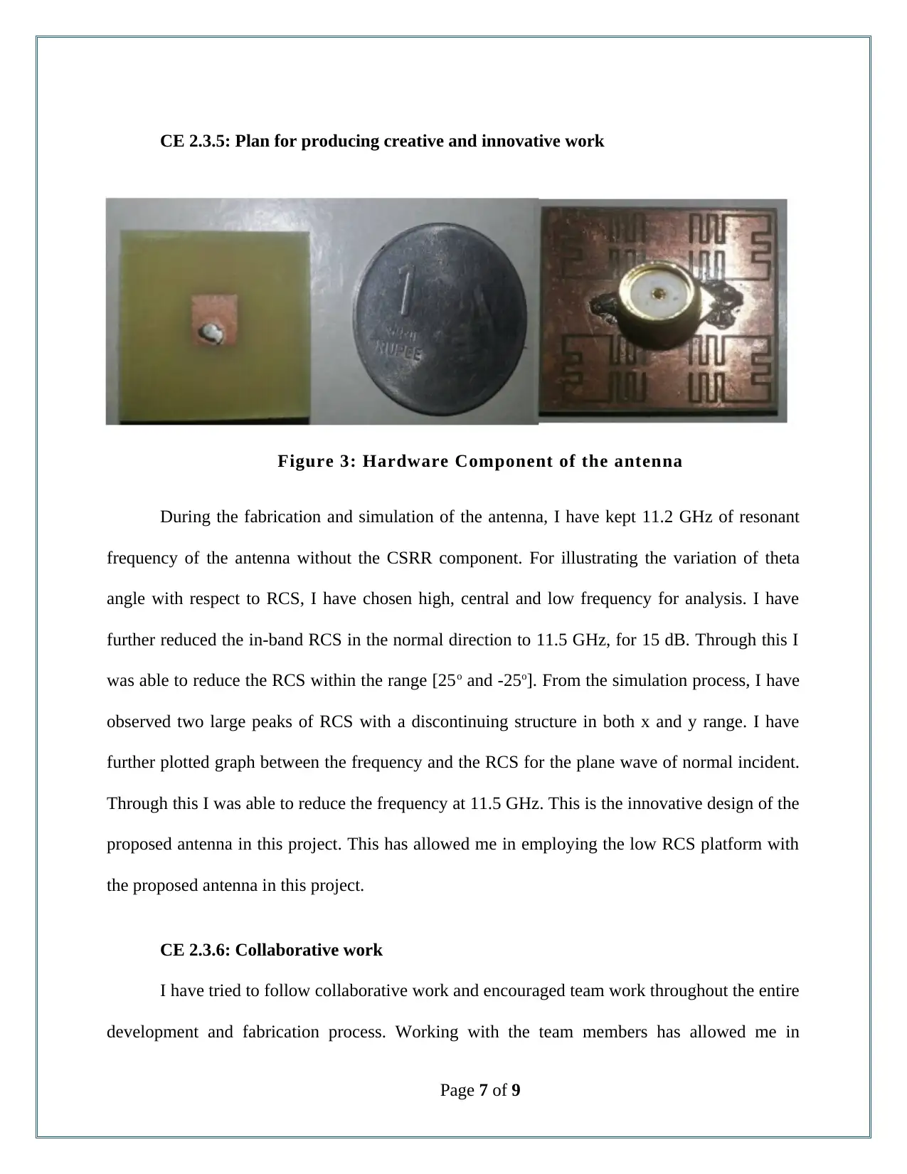
Figure 3: Hardware Component of the antenna
During the fabrication and simulation of the antenna, I have kept 11.2 GHz of resonant
frequency of the antenna without the CSRR component. For illustrating the variation of theta
angle with respect to RCS, I have chosen high, central and low frequency for analysis. I have
further reduced the in-band RCS in the normal direction to 11.5 GHz, for 15 dB. Through this I
was able to reduce the RCS within the range [25o and -25o]. From the simulation process, I have
observed two large peaks of RCS with a discontinuing structure in both x and y range. I have
further plotted graph between the frequency and the RCS for the plane wave of normal incident.
Through this I was able to reduce the frequency at 11.5 GHz. This is the innovative design of the
proposed antenna in this project. This has allowed me in employing the low RCS platform with
the proposed antenna in this project.
CE 2.3.6: Collaborative work
I have tried to follow collaborative work and encouraged team work throughout the entire
development and fabrication process. Working with the team members has allowed me in
Page 7 of 9
reducing the work load and completing the task with increased efficiency and work distribution.
I have regularly discussed the antenna fabrication plan and ensured the information flow from
the assistant teacher to the team members working beside me in this project.
CE 2.4: Project Review
CE 2.4.1: Project Overview
Overview: The micro strip antenna that I have considered for the advanced design in this
project has allowed me in implementing the proposed strategy of RCS reduction. Though this
project, I was able to present the revised structure of the micro strip antenna while etching the
four CSRR components at each side of the antenna. The antenna with included CSRR has
showed significant reduction in the RCS components.
Output: From the analysis and evaluation of the developed antenna, I have observed that
the resonant frequency of the antenna was 11.2 GHz, without the CSRR. In addition to that the
reflection coefficient measured for the antenna was found to be – 40 dB. Furthermore, the
designed antenna in this project has shown significant reduction of RCS for 111.5 GHz
frequency.
CE 2.4.2: My contribution to work
I have identified the current vulnerabilities of the micro strip antenna in term of CSRR
components. I have proposed an advanced plan and design of the micro strip antenna required for
reducing the RCS components and increasing the efficiency. Through the project, I have showed
and used my technical understanding of antenna design for achieving considerable success in the
project.
Page 8 of 9
⊘ This is a preview!⊘
Do you want full access?
Subscribe today to unlock all pages.

Trusted by 1+ million students worldwide
1 out of 9
Related Documents
Your All-in-One AI-Powered Toolkit for Academic Success.
+13062052269
info@desklib.com
Available 24*7 on WhatsApp / Email
![[object Object]](/_next/static/media/star-bottom.7253800d.svg)
Unlock your academic potential
Copyright © 2020–2025 A2Z Services. All Rights Reserved. Developed and managed by ZUCOL.


