ProductsLogo
LogoStudy Documents
LogoAI Grader
LogoAI Answer
LogoAI Code Checker
LogoPlagiarism Checker
LogoAI Paraphraser
LogoAI Quiz
LogoAI Detector
PricingBlogAbout Us
logo

The Vapour Compression Refrigeration Cycle

Verified

Added on  2023/04/21

|9
|1420
|474
AI Summary
This article provides an overview of the vapor compression refrigeration cycle and its applications. It explains the parameters that affect the cycle's performance and how to calculate the coefficient of performance. The article also discusses the variations between ideal and actual refrigeration cycles and offers suggestions for improving efficiency. Detailed results and analysis are provided.

Contribute Materials

Your contribution can guide someone’s learning journey. Share your documents today.
Document Page
THE VAPOUR COMPRESSION REFRIGERATION CYCLE
By Name
Course
Instructor
Institution
Location
Date

Secure Best Marks with AI Grader

Need help grading? Try our AI Grader for instant feedback on your assignments.
Document Page
Introduction/Background
The vapor compression cycle has found applications in numerous industrial, medical as well as
domestic applications all over the world. Air conditions medical preservations as well as food
preservations alongside transport are among the applications that to a very great extent depend
on the use of the refrigeration plant. It is of importance thus that engineering students have a
grasp and be informed of the numerous parameters that influence the performance of the vapor
refraction cycle for the purposes of the design or utilizations of such a plant (Babarinde et al.,
2015). The design of the Hilton Refrigeration Laboratory Unit has been done to enable learners
to gain a full investigation of the vapor compression performance under different conditions of
evaporator load as well as condense preserve. All the useful parameters are instrumented and the
unit is entirely safe for the system to be operated by the student.
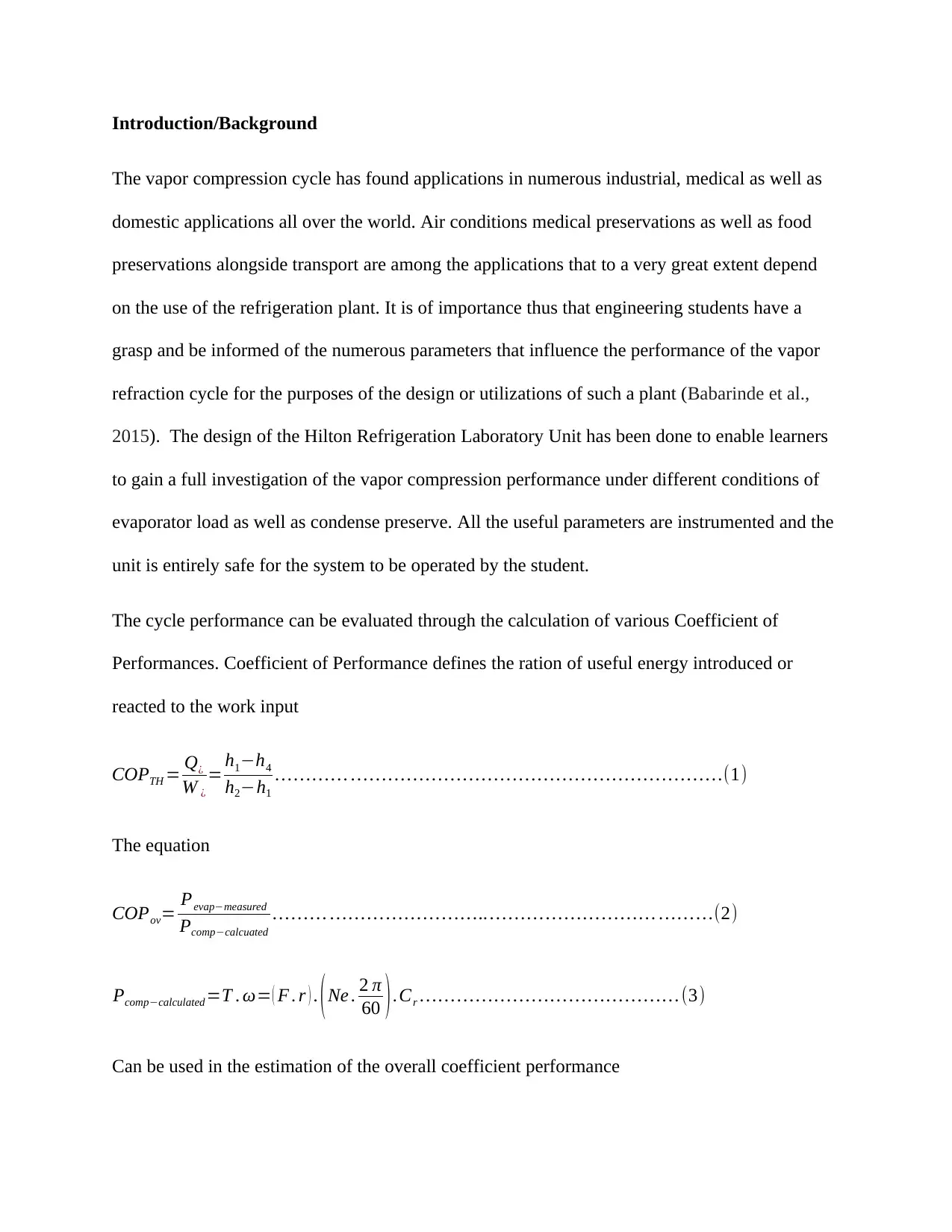
The cycle performance can be evaluated through the calculation of various Coefficient of
Performances. Coefficient of Performance defines the ration of useful energy introduced or
reacted to the work input
COPTH = Q¿
W ¿
= h1h4
h2h1
(1)
The equation
COPov= Pevapmeasured
Pcompcalcuated
.. (2)
Pcompcalculated =T . ω= ( F . r ) . (Ne . 2 π
60 ).Cr (3)
Can be used in the estimation of the overall coefficient performance
Document Page
where Pcomp is the power of the compressor estimated using the compressor speed, T is the
torque, F, force of spring balance, Ne the diameter of the pulley belt ratio, Cr=3.08, r=165 which
is the radius of the dynamometer
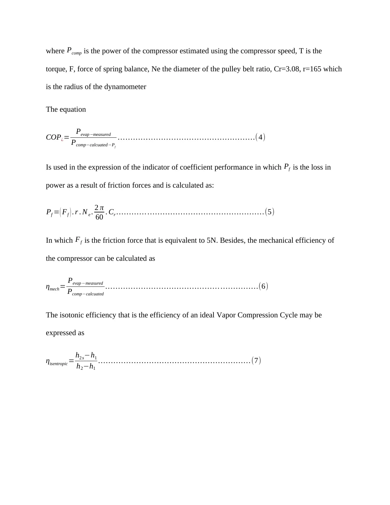
The equation
COP¿= Pevap measured
PcompcalcuatedPf
( 4)
Is used in the expression of the indicator of coefficient performance in which Pf is the loss in
power as a result of friction forces and is calculated as:
Pf = ( Ff ) . r . N e . 2 π
60 . Cr .(5)
In which Ff is the friction force that is equivalent to 5N. Besides, the mechanical efficiency of
the compressor can be calculated as
ηmech = Pevap measured
Pcompcalcuated
(6)
The isotonic efficiency that is the efficiency of an ideal Vapor Compression Cycle may be
expressed as
ηisentropic = h2 sh1
h2h1
(7)
Document Page
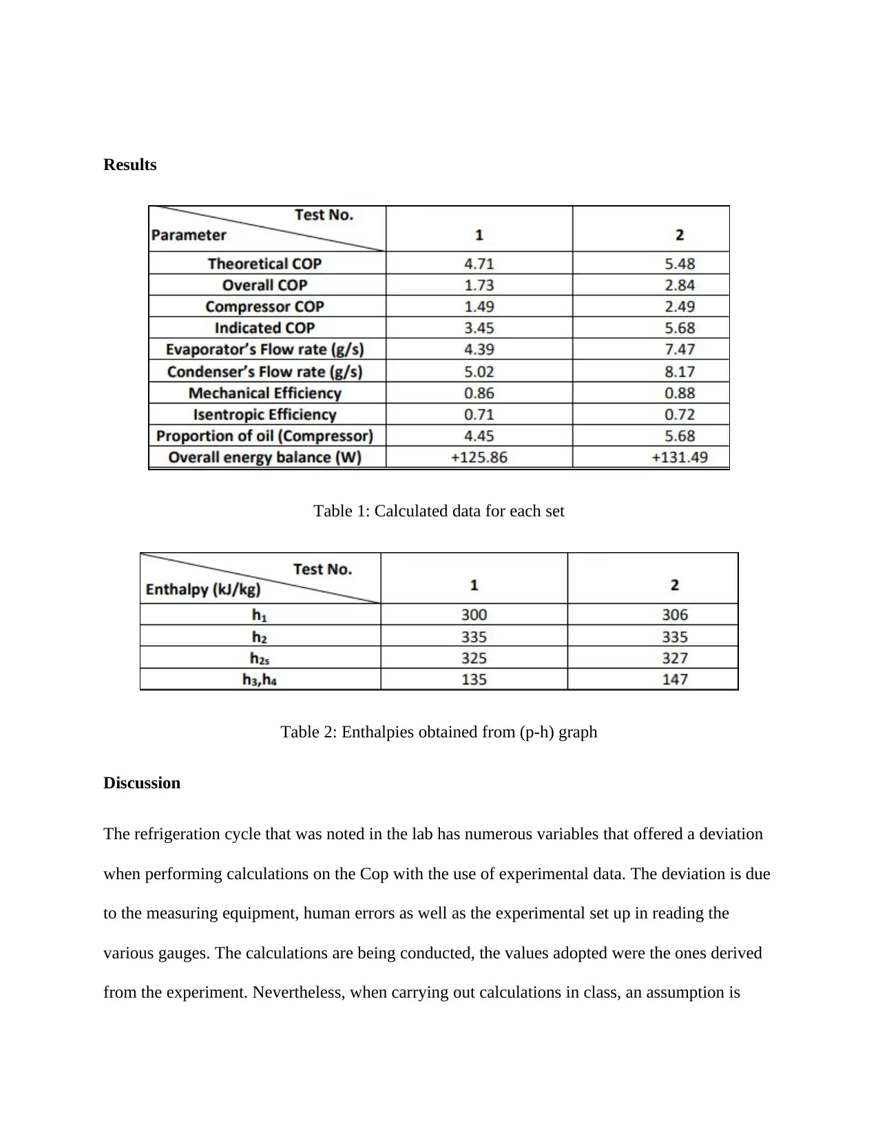
Results
Table 1: Calculated data for each set
Table 2: Enthalpies obtained from (p-h) graph
Discussion
The refrigeration cycle that was noted in the lab has numerous variables that offered a deviation
when performing calculations on the Cop with the use of experimental data. The deviation is due
to the measuring equipment, human errors as well as the experimental set up in reading the
various gauges. The calculations are being conducted, the values adopted were the ones derived
from the experiment. Nevertheless, when carrying out calculations in class, an assumption is

Paraphrase This Document

Need a fresh take? Get an instant paraphrase of this document with our AI Paraphraser
Document Page
made that the refrigeration cycles is idea. In either way there are a few assumptions that are taken
to make the calculations simpler
Variation in the experimental and ideal refrigeration cycle
There are numerous variations in the calculations that are involved in an ideal refrigeration
cycles as well as the actual regulation cycle. For the case of ideal refrigeration cycle, an
assumption is made that the drops in pressure is neglible, the condenser as well as the evaporator
are adiabatic and the compressor not being isentropic (Haida et al., 2016). No more work will be
needed to get to state 2 from state 1 as the compressor is isentropic and hence the work input will
be enhanced that impacts the COP. The benefits of Cop are defined by equation 4 in which the
cost is the work input and thus the COP would be higher than that of the ideal cycle in
comparison with the actual cycle.
Variation in h2 with the use of various methods
The first methods make use of energy balance over the conductor to determine h2. h2 is
determined to be 63.25 kJ/kg. On the other hand, the second method makes use of the efficiency
of the compressor to determine h2 and the estimations were 620.25 kJ/kg (Cho and Park, 2016).
The two methods made use of the data from the initial trial and from the calculations it can be
established that method 2 offers a more accurate h2 value since there is limited experimental data
involved in the calculations.
To get higher values of COP, the actual cycle should work as closely as possible to the ideal
cycle. This insinuates that such irreversibility’s including drop in pressure as a result of friction,
as well as heat transfer to the surrounding should be reduced. Heat transfer to the environment
may be reduced through insulation of the exposed piping more specifically the evaporator and
Document Page
condenser. Nevertheless, the apparatus in the laboratory was most probably left to enable the
learner have a view of the contents of the evaporator as well as condenser. The undesirable
transfer of heat is available between the surrounding and the device at the evaporator and
condensers in the high to low temperature direction.
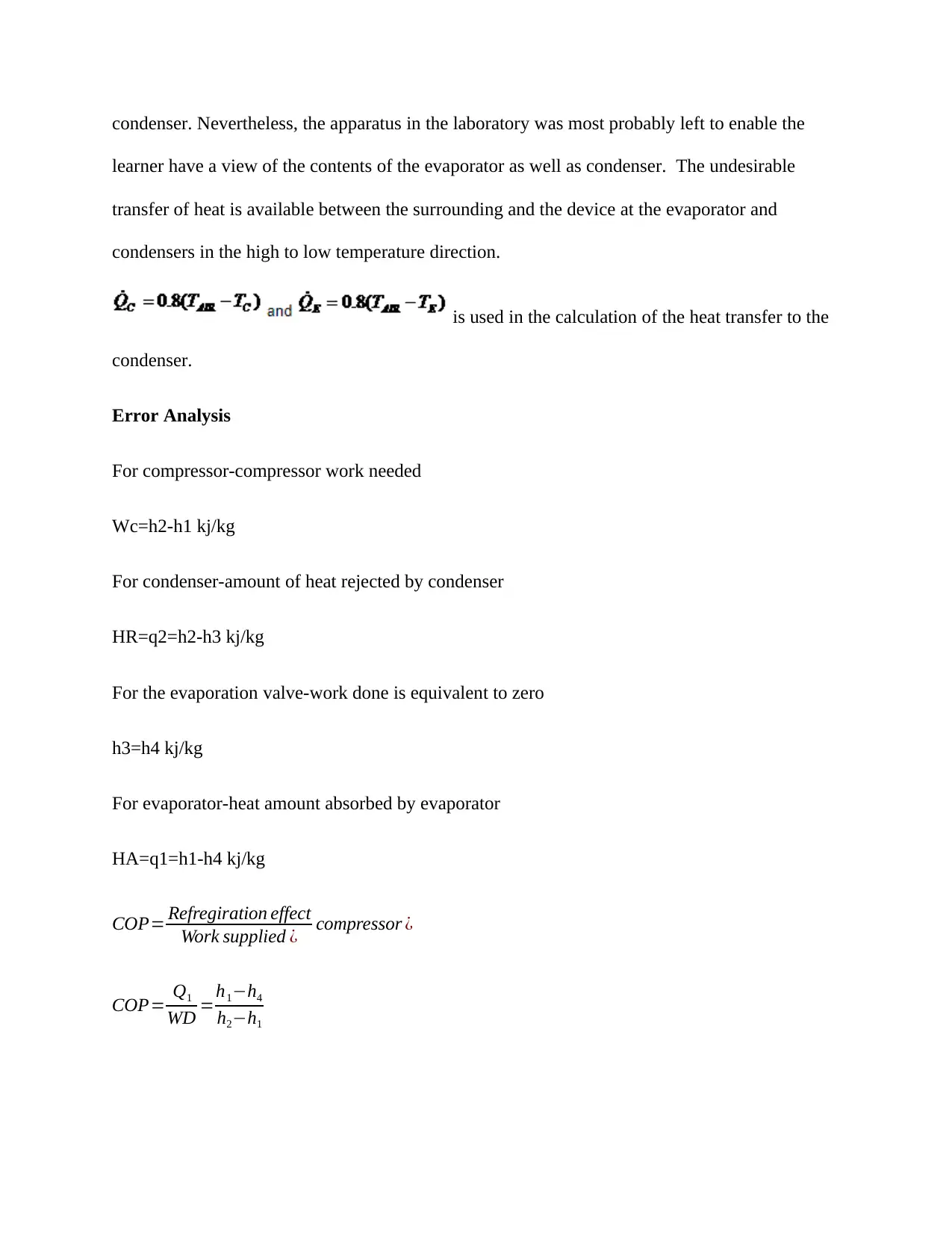
is used in the calculation of the heat transfer to the
condenser.
Error Analysis
For compressor-compressor work needed
Wc=h2-h1 kj/kg
For condenser-amount of heat rejected by condenser
HR=q2=h2-h3 kj/kg
For the evaporation valve-work done is equivalent to zero
h3=h4 kj/kg
For evaporator-heat amount absorbed by evaporator
HA=q1=h1-h4 kj/kg
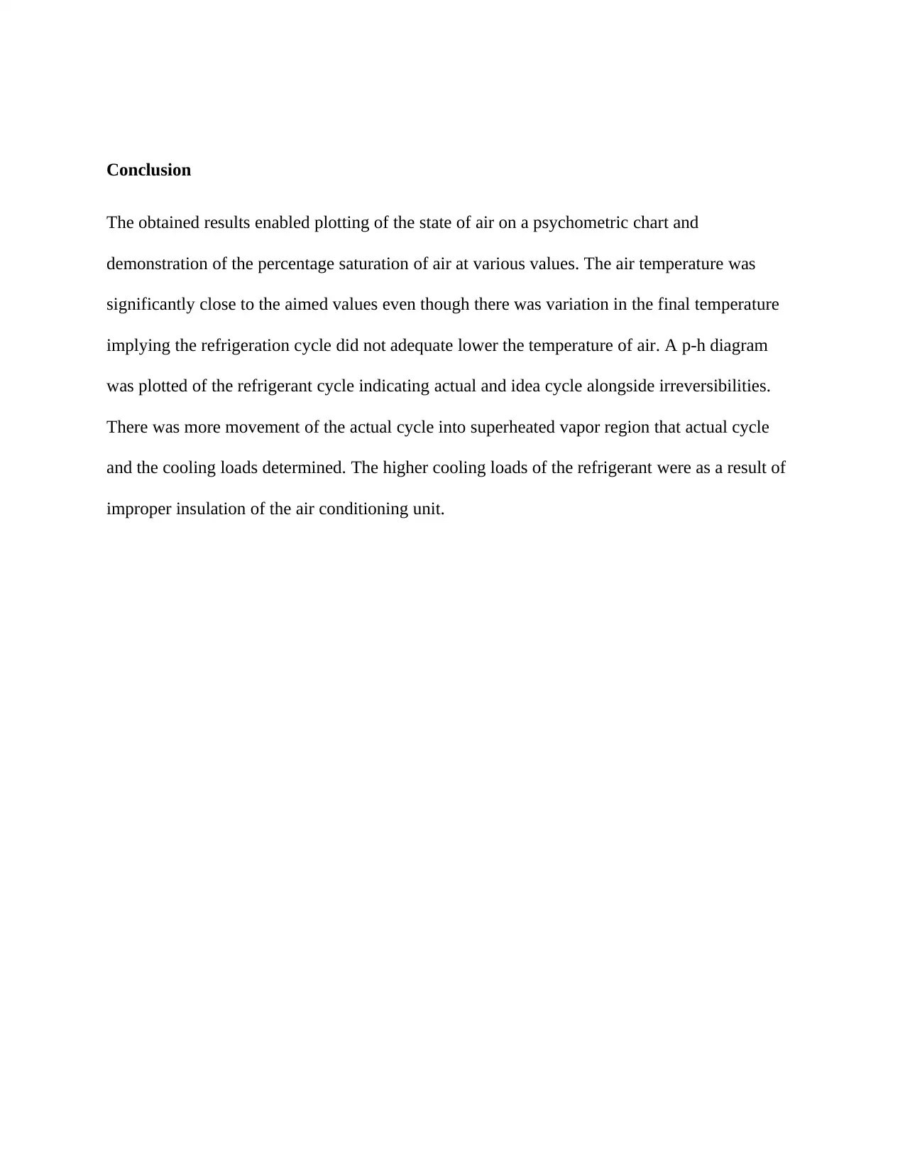
COP= Refregiration effect
Work supplied ¿ compressor ¿
COP= Q1
WD =h1h4
h2h1
Document Page
Conclusion
The obtained results enabled plotting of the state of air on a psychometric chart and
demonstration of the percentage saturation of air at various values. The air temperature was
significantly close to the aimed values even though there was variation in the final temperature
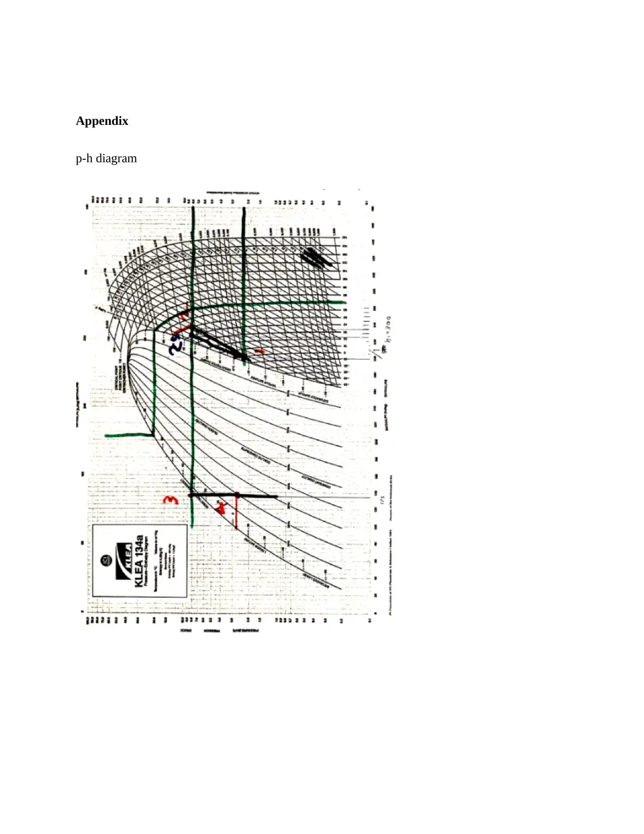
implying the refrigeration cycle did not adequate lower the temperature of air. A p-h diagram
was plotted of the refrigerant cycle indicating actual and idea cycle alongside irreversibilities.
There was more movement of the actual cycle into superheated vapor region that actual cycle
and the cooling loads determined. The higher cooling loads of the refrigerant were as a result of
improper insulation of the air conditioning unit.

Secure Best Marks with AI Grader

Need help grading? Try our AI Grader for instant feedback on your assignments.
Document Page
References
Babarinde, T.O., Ohunakin, O.S., Adelekan, D.S., Aasa, S.A. and Oyedepo, S.O., 2015.
Experimental study of LPG and R134a refrigerants in vapor compression
refrigeration. International Journal of Energy for a Clean Environment, 16(1-4)
Cho, H. and Park, C., 2016. Experimental investigation of performance and exergy analysis of
automotive air conditioning systems using refrigerant R1234yf at various compressor
speeds. Applied Thermal Engineering, 101, pp.30-37
Gao, W.Z., Cheng, Y.P., Jiang, A.G., Liu, T. and Anderson, K., 2015. Experimental
investigation on integrated liquid desiccant–Indirect evaporative air cooling system utilizing the
Maisotesenko–Cycle. Applied Thermal Engineering, 88, pp.288-296
Haida, M., Banasiak, K., Smolka, J., Hafner, A. and Eikevik, T.M., 2016. Experimental analysis
of the R744 vapour compression rack equipped with the multi-ejector expansion work recovery
module. international journal of refrigeration, 64, pp.93-107
Document Page
Appendix
p-h diagram
1 out of 9
[object Object]

Your All-in-One AI-Powered Toolkit for Academic Success.

Available 24*7 on WhatsApp / Email

[object Object]