Thermodynamic Analysis of Pumps: Performance and Analysis Report
VerifiedAdded on 2023/01/23
|8
|1784
|97
Report
AI Summary
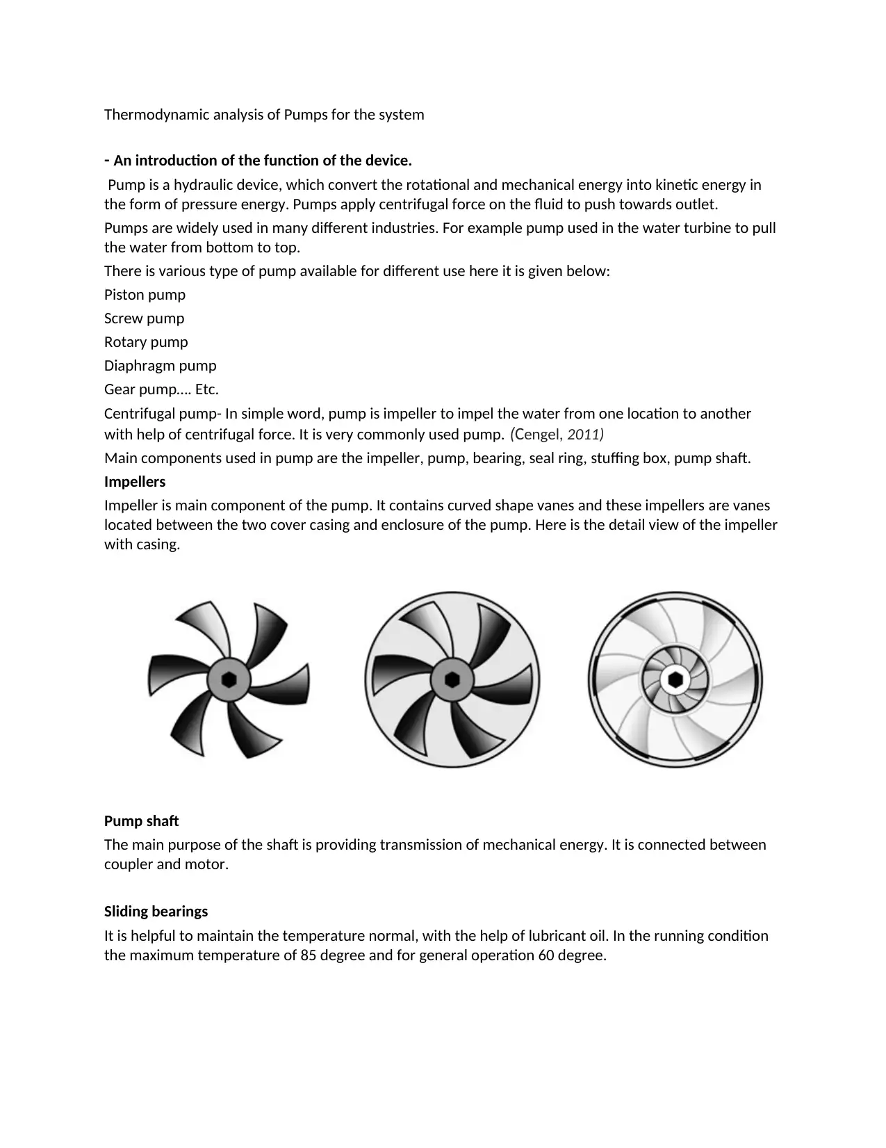
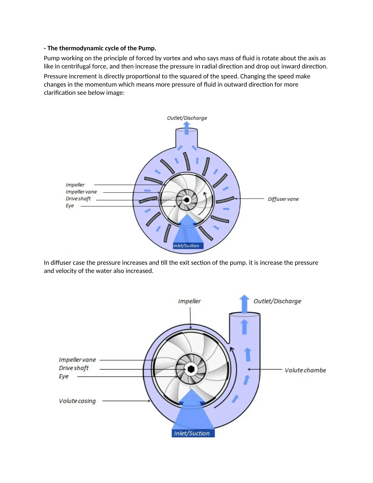
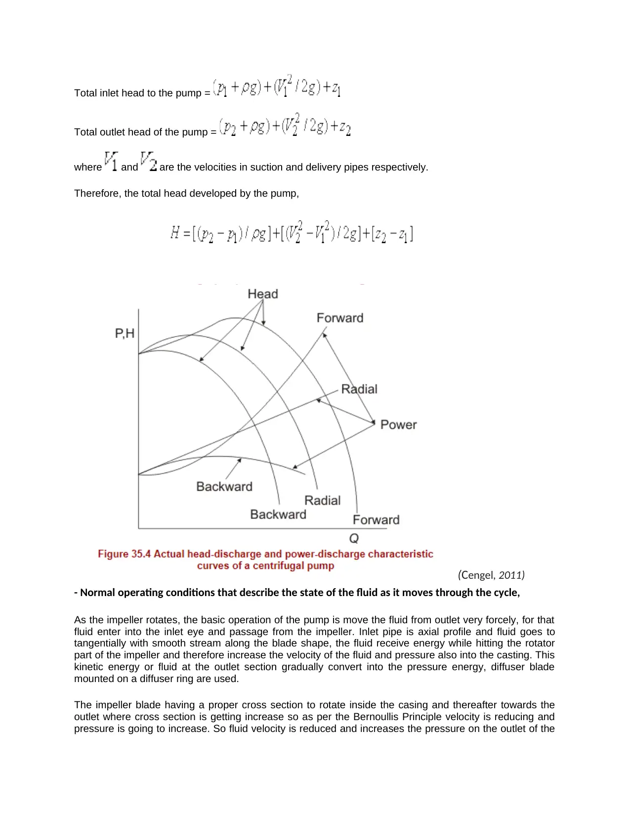
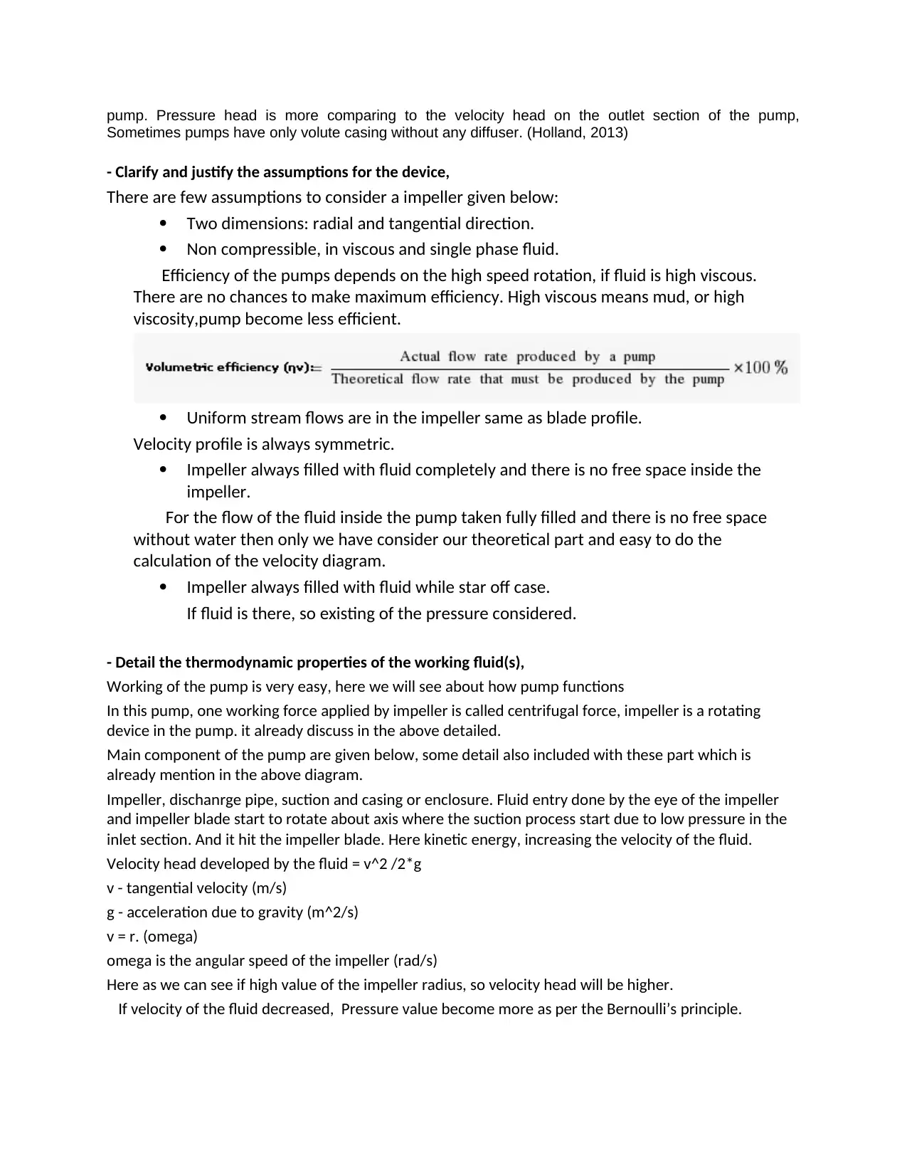
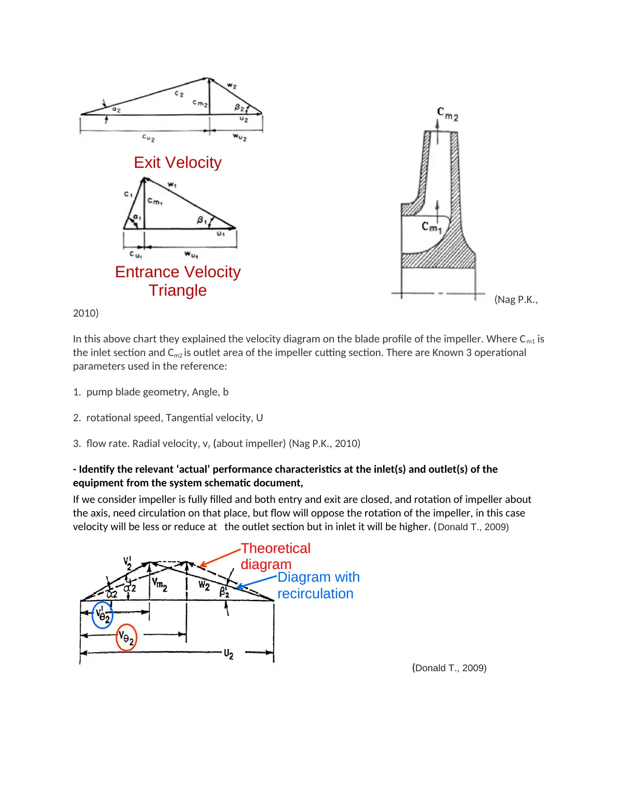
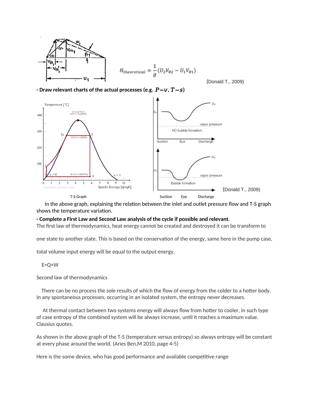
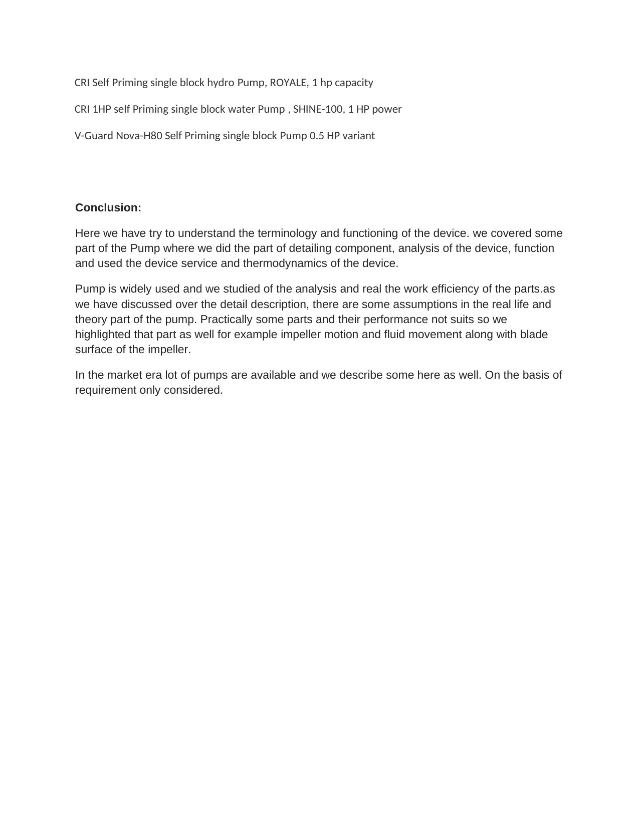
This report provides a detailed thermodynamic analysis of pumps, beginning with an introduction to their function and applications across various industries. It explores different pump types, with a focus on centrifugal pumps, and details key components like impellers, pump shafts, and bearings. The report delves into the thermodynamic cycle of pumps, explaining how they convert mechanical energy into kinetic energy, increasing fluid pressure. It examines operating conditions, assumptions, and the thermodynamic properties of working fluids, including the application of Bernoulli's principle. The analysis includes velocity triangles, T-S graphs, and the application of the First and Second Laws of Thermodynamics. The report concludes with a discussion of pump performance characteristics, relevant charts, and a review of commercially available pump models.
1 out of 8
Related Documents


Your All-in-One AI-Powered Toolkit for Academic Success.
+13062052269
info@desklib.com
Available 24*7 on WhatsApp / Email
![[object Object]](/_next/static/media/star-bottom.7253800d.svg)
Copyright © 2020–2026 A2Z Services. All Rights Reserved. Developed and managed by ZUCOL.