Thermodynamics and Heat Engines: Engine Efficiency and Processes
VerifiedAdded on 2023/03/30
|12
|2732
|459
Report
AI Summary
This report delves into the principles of thermodynamics as applied to internal combustion engines, specifically focusing on the Otto and Diesel cycles. It provides detailed descriptions of the operational sequences of four-stroke spark-ignition and compression-ignition engines, illustrating each stroke with diagrams. The report then explains the mechanical efficiency of two-stroke and four-stroke engines, highlighting the factors that influence efficiency, such as friction and energy loss. Furthermore, it describes the thermodynamic processes involved in both Otto and Diesel cycles, including isentropic compression, isobaric or isochoric expansion, and isochoric decompression. The report also explores methods to improve the efficiency of both Otto and Diesel heat engines, such as reducing friction, leakages, and heat loss. The document concludes with a brief explanation of two-stroke engines and their operational principles.
Thermodynamics 1
THERMODYNAMICS
By Name
Course
Instructor
Institution
Location
Date
THERMODYNAMICS
By Name
Course
Instructor
Institution
Location
Date
Paraphrase This Document
Need a fresh take? Get an instant paraphrase of this document with our AI Paraphraser
Thermodynamics 2
P8
The Four-stroke-cycle spark-ignition engine
Spark ignition engine is an IC engine that basically operates on petrol, the mixture air and fuel is
ignited from a spark plug in this engine. The operation sequence of this type includes four
sequences as discussed below;
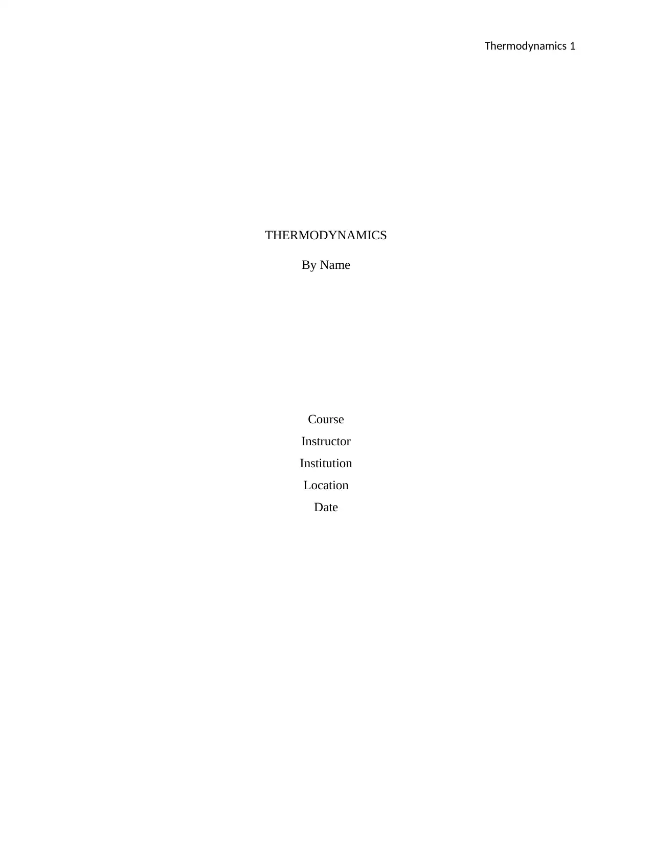
First sequence: ignition stroke: here the inlet valve will open therefore the piston movement
will develop a suction pressure which will induce fresh charge of air as well as atomized petrol.
The stroke is sometimes known as the intake stroke. This stroke can be illustrated using the
following diagram;
Figure 1: Showing ignition stroke (Blair, 2011).
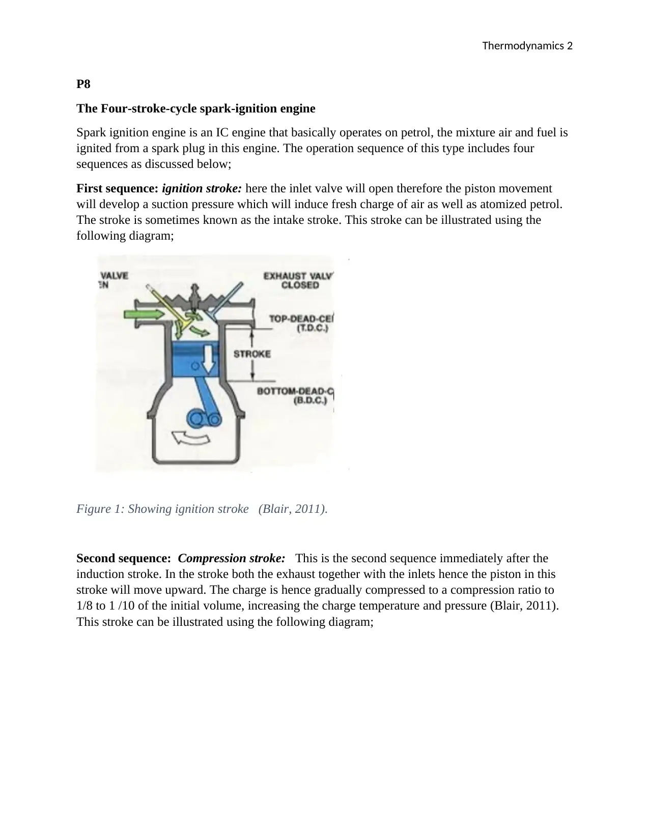
Second sequence: Compression stroke: This is the second sequence immediately after the
induction stroke. In the stroke both the exhaust together with the inlets hence the piston in this
stroke will move upward. The charge is hence gradually compressed to a compression ratio to
1/8 to 1 /10 of the initial volume, increasing the charge temperature and pressure (Blair, 2011).
This stroke can be illustrated using the following diagram;
Thermodynamics 3
Figure 2: Showing Compression stroke (Blair, 2011).
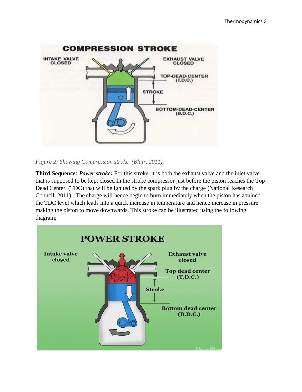
Third Sequence: Power stroke: For this stroke, it is both the exhaust valve and the inlet valve
that is supposed to be kept closed In the stroke compressor just before the piston reaches the Top
Dead Center (TDC) that will be ignited by the spark plug by the charge (National Research
Council, 2011) . The charge will hence begin to burn immediately when the piston has attained
the TDC level which leads into a quick increase in temperature and hence increase in pressure
making the piston to move downwards. This stroke can be illustrated using the following
diagram;
⊘ This is a preview!⊘
Do you want full access?
Subscribe today to unlock all pages.

Trusted by 1+ million students worldwide
Thermodynamics 4
Figure 3: Showing power stroke (Blair, 2011).
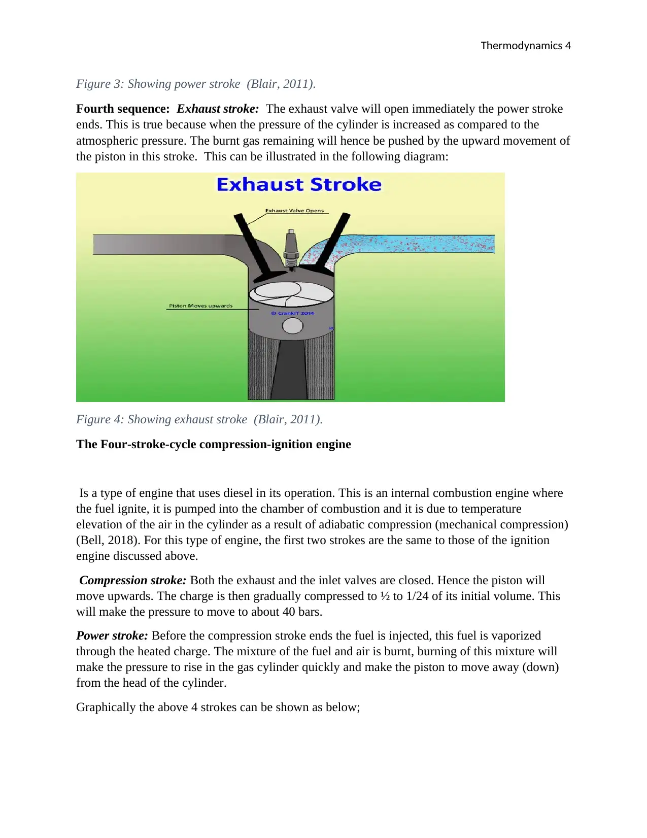
Fourth sequence: Exhaust stroke: The exhaust valve will open immediately the power stroke
ends. This is true because when the pressure of the cylinder is increased as compared to the
atmospheric pressure. The burnt gas remaining will hence be pushed by the upward movement of
the piston in this stroke. This can be illustrated in the following diagram:
Figure 4: Showing exhaust stroke (Blair, 2011).
The Four-stroke-cycle compression-ignition engine
Is a type of engine that uses diesel in its operation. This is an internal combustion engine where
the fuel ignite, it is pumped into the chamber of combustion and it is due to temperature
elevation of the air in the cylinder as a result of adiabatic compression (mechanical compression)
(Bell, 2018). For this type of engine, the first two strokes are the same to those of the ignition
engine discussed above.
Compression stroke: Both the exhaust and the inlet valves are closed. Hence the piston will
move upwards. The charge is then gradually compressed to ½ to 1/24 of its initial volume. This
will make the pressure to move to about 40 bars.
Power stroke: Before the compression stroke ends the fuel is injected, this fuel is vaporized
through the heated charge. The mixture of the fuel and air is burnt, burning of this mixture will
make the pressure to rise in the gas cylinder quickly and make the piston to move away (down)
from the head of the cylinder.
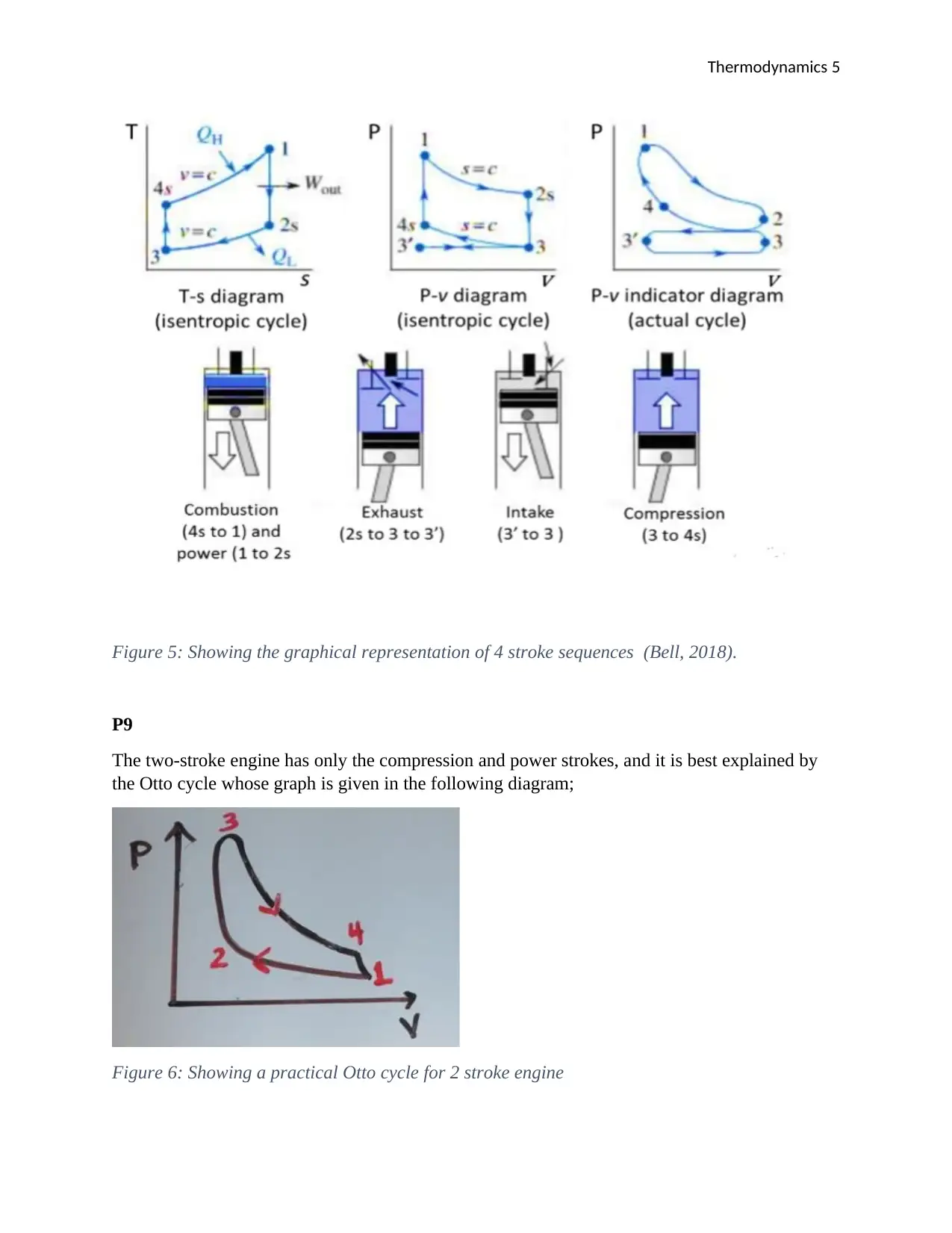
Graphically the above 4 strokes can be shown as below;
Paraphrase This Document
Need a fresh take? Get an instant paraphrase of this document with our AI Paraphraser
Thermodynamics 5
Figure 5: Showing the graphical representation of 4 stroke sequences (Bell, 2018).
P9
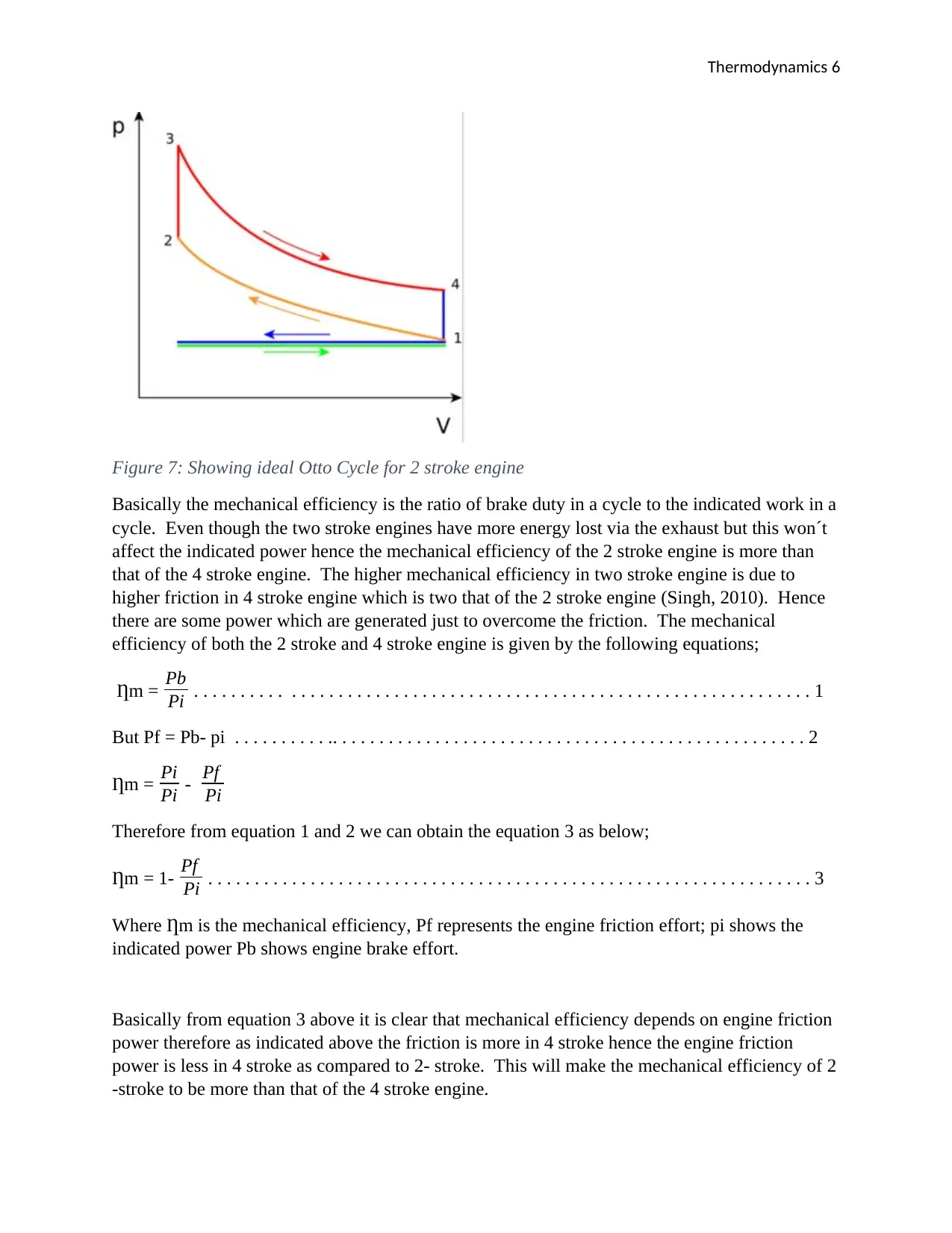
The two-stroke engine has only the compression and power strokes, and it is best explained by
the Otto cycle whose graph is given in the following diagram;
Figure 6: Showing a practical Otto cycle for 2 stroke engine
Thermodynamics 6
Figure 7: Showing ideal Otto Cycle for 2 stroke engine
Basically the mechanical efficiency is the ratio of brake duty in a cycle to the indicated work in a
cycle. Even though the two stroke engines have more energy lost via the exhaust but this won´t
affect the indicated power hence the mechanical efficiency of the 2 stroke engine is more than
that of the 4 stroke engine. The higher mechanical efficiency in two stroke engine is due to
higher friction in 4 stroke engine which is two that of the 2 stroke engine (Singh, 2010). Hence
there are some power which are generated just to overcome the friction. The mechanical
efficiency of both the 2 stroke and 4 stroke engine is given by the following equations;
Ƞm = Pb
Pi . . . . . . . . . . . . . . . . . . . . . . . . . . . . . . . . . . . . . . . . . . . . . . . . . . . . . . . . . . . . . . . . . . 1
But Pf = Pb- pi . . . . . . . . . . .. . . . . . . . . . . . . . . . . . . . . . . . . . . . . . . . . . . . . . . . . . . . . . . . . . . 2
Ƞm = Pi
Pi - Pf
Pi
Therefore from equation 1 and 2 we can obtain the equation 3 as below;
Ƞm = 1- Pf
Pi . . . . . . . . . . . . . . . . . . . . . . . . . . . . . . . . . . . . . . . . . . . . . . . . . . . . . . . . . . . . . . . . . 3
Where Ƞm is the mechanical efficiency, Pf represents the engine friction effort; pi shows the
indicated power Pb shows engine brake effort.
Basically from equation 3 above it is clear that mechanical efficiency depends on engine friction
power therefore as indicated above the friction is more in 4 stroke hence the engine friction
power is less in 4 stroke as compared to 2- stroke. This will make the mechanical efficiency of 2
-stroke to be more than that of the 4 stroke engine.
⊘ This is a preview!⊘
Do you want full access?
Subscribe today to unlock all pages.

Trusted by 1+ million students worldwide
Thermodynamics 7
DESCRIBE THE THERMODYNAMIC PROCESS OF AN OTTO CYCLE
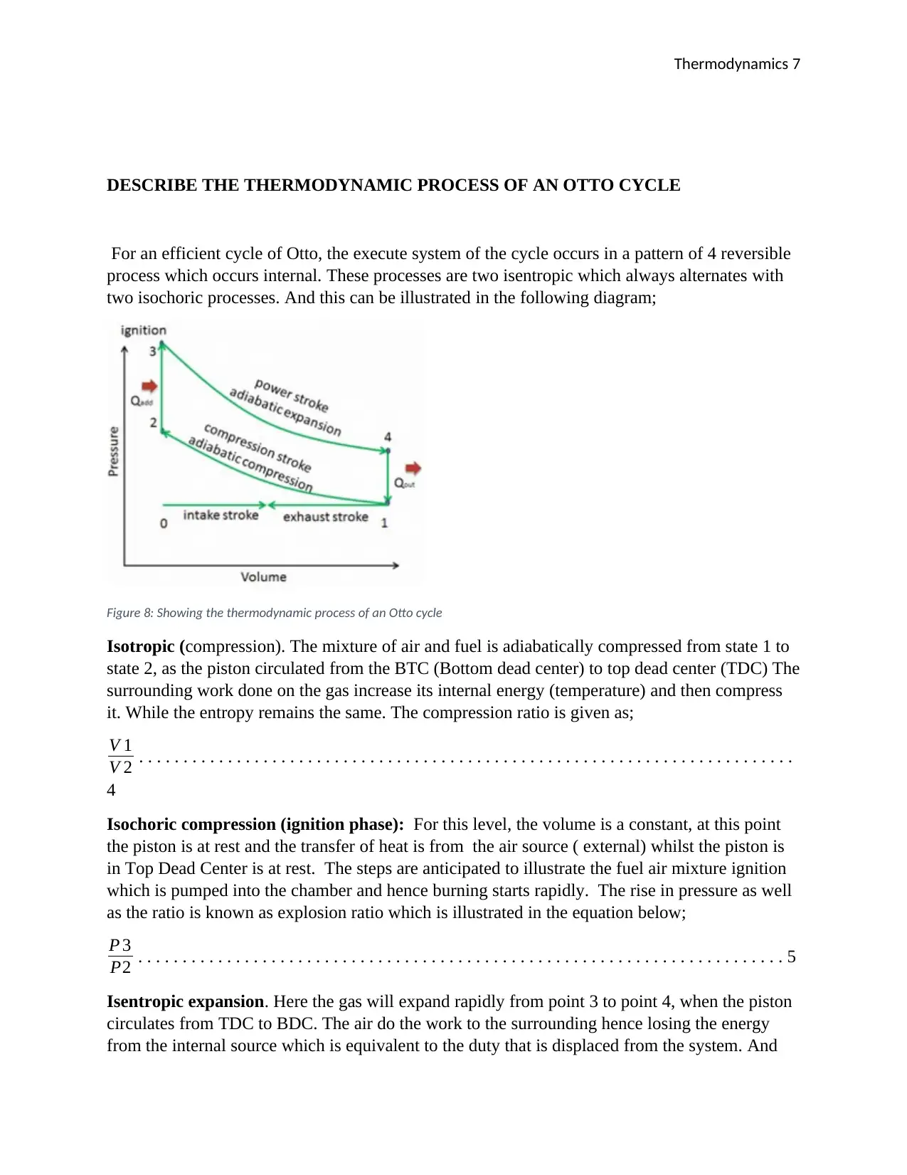
For an efficient cycle of Otto, the execute system of the cycle occurs in a pattern of 4 reversible
process which occurs internal. These processes are two isentropic which always alternates with
two isochoric processes. And this can be illustrated in the following diagram;
Figure 8: Showing the thermodynamic process of an Otto cycle
Isotropic (compression). The mixture of air and fuel is adiabatically compressed from state 1 to
state 2, as the piston circulated from the BTC (Bottom dead center) to top dead center (TDC) The
surrounding work done on the gas increase its internal energy (temperature) and then compress
it. While the entropy remains the same. The compression ratio is given as;
V 1
V 2 . . . . . . . . . . . . . . . . . . . . . . . . . . . . . . . . . . . . . . . . . . . . . . . . . . . . . . . . . . . . . . . . . . . . . . . . . .
4
Isochoric compression (ignition phase): For this level, the volume is a constant, at this point
the piston is at rest and the transfer of heat is from the air source ( external) whilst the piston is
in Top Dead Center is at rest. The steps are anticipated to illustrate the fuel air mixture ignition
which is pumped into the chamber and hence burning starts rapidly. The rise in pressure as well
as the ratio is known as explosion ratio which is illustrated in the equation below;
P 3
P2 . . . . . . . . . . . . . . . . . . . . . . . . . . . . . . . . . . . . . . . . . . . . . . . . . . . . . . . . . . . . . . . . . . . . . . . . . 5
Isentropic expansion. Here the gas will expand rapidly from point 3 to point 4, when the piston
circulates from TDC to BDC. The air do the work to the surrounding hence losing the energy
from the internal source which is equivalent to the duty that is displaced from the system. And
Paraphrase This Document
Need a fresh take? Get an instant paraphrase of this document with our AI Paraphraser
Thermodynamics 8
this, entropy remains constant. The ratio in volume which is illustrated by the below equation is
the isentropic expansion ratio
V 4
V 3 . . . . . . . . . . . . . . . . . . . . . . . . . . . . .. . . . . . .. . . . . . . . . . . . . . . . . . . . . . . . . . . . . . . . . . . . . 6
Isochoric decompression (Which is also known as exhaust stroke): For this phase, completion
of the cycle is done through a constant volume where the heat eliminated from the surroundings
whilst the piston at the point BDC. Working pressure of the gas reduces dramatically from point
4 to point 1. And then the valve for exhaust will open at point 4. And the exhaust stroke is then
closed immediately after the decomposition.
Thermodynamic Processes in Diesel Cycle
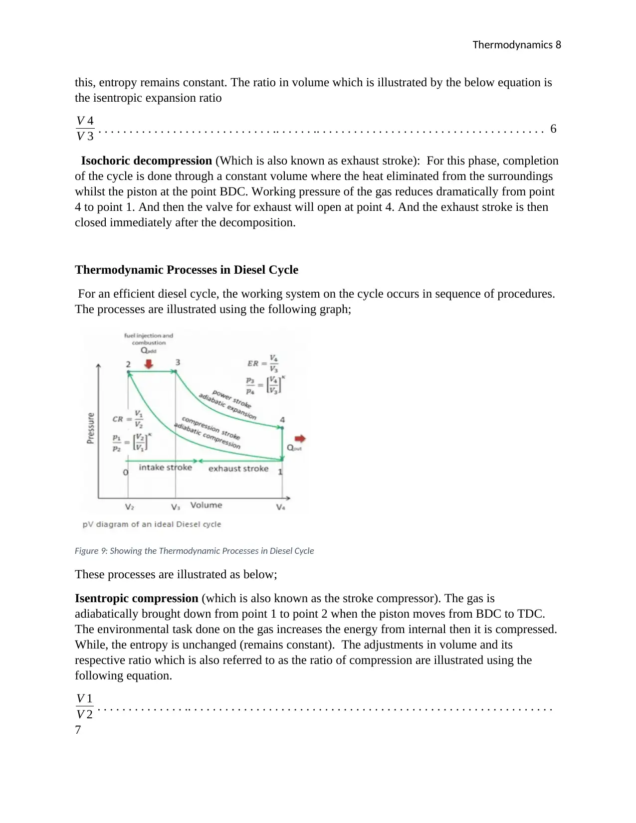
For an efficient diesel cycle, the working system on the cycle occurs in sequence of procedures.
The processes are illustrated using the following graph;
Figure 9: Showing the Thermodynamic Processes in Diesel Cycle
These processes are illustrated as below;
Isentropic compression (which is also known as the stroke compressor). The gas is
adiabatically brought down from point 1 to point 2 when the piston moves from BDC to TDC.
The environmental task done on the gas increases the energy from internal then it is compressed.
While, the entropy is unchanged (remains constant). The adjustments in volume and its
respective ratio which is also referred to as the ratio of compression are illustrated using the
following equation.
V 1
V 2 . . . . . . . . . . . . . . .. . . . . . . . . . . . . . . . . . . . . . . . . . . . . . . . . . . . . . . . . . . . . . . . . . . . . . . . . . .
7
Thermodynamics 9
Isobaric expansion (Ignition phase)
For this case which is in state 2 and state 3, there is an unchanged pressure heat transfer to the air
from an external source and the piston moves towards the V3. In the unchanged pressure
process, energy enters the system as heat Qadd and the work is done through moving the piston.
Isentropic expansion (Power Stroke): The gas will adiabatically expand from point 3 to point 4,
as the piston moves from V3 to the BDC. The gas does work on the environment and then loses
internal energy equal to the work which leaves the system. And the entropy remains constant and
the volume ratio which is known as the isentropic expansion ratio is given using the equation
below;
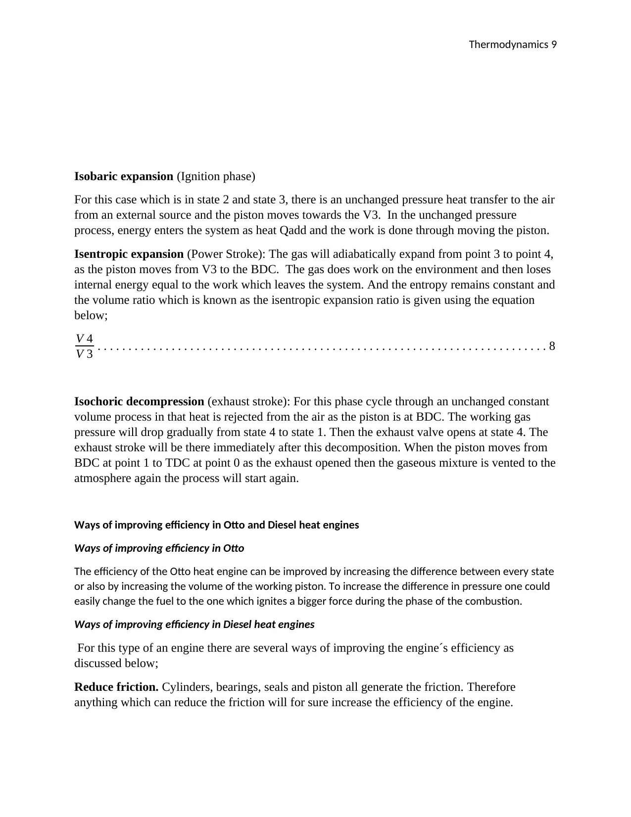
V 4
V 3 . . . . . . . . . . . . . . . . . . . . . . . . . . . . . . . . . . . . . . . . . . . . . . . . . . . . . . . . . . . . . . . . . . . . . . . . . 8
Isochoric decompression (exhaust stroke): For this phase cycle through an unchanged constant
volume process in that heat is rejected from the air as the piston is at BDC. The working gas
pressure will drop gradually from state 4 to state 1. Then the exhaust valve opens at state 4. The
exhaust stroke will be there immediately after this decomposition. When the piston moves from
BDC at point 1 to TDC at point 0 as the exhaust opened then the gaseous mixture is vented to the
atmosphere again the process will start again.
Ways of improving efficiency in Otto and Diesel heat engines
Ways of improving efficiency in Otto
The efficiency of the Otto heat engine can be improved by increasing the difference between every state
or also by increasing the volume of the working piston. To increase the difference in pressure one could
easily change the fuel to the one which ignites a bigger force during the phase of the combustion.
Ways of improving efficiency in Diesel heat engines
For this type of an engine there are several ways of improving the engine´s efficiency as
discussed below;
Reduce friction. Cylinders, bearings, seals and piston all generate the friction. Therefore
anything which can reduce the friction will for sure increase the efficiency of the engine.
⊘ This is a preview!⊘
Do you want full access?
Subscribe today to unlock all pages.

Trusted by 1+ million students worldwide
Thermodynamics 10
Reduce leakages: seals sometimes are a source of friction but at the same time they reduce the
leakages. For any flow which does not go via the work generating cycle is power lost.
Reduce the heat loss: Thermal breaks, as well as insulating, prevents the energy loss which
could go to power. In the engine piston, for instance, ceramics coated piston and cylinder head
are capable of reducing the heat loss (Blair, 2011).
Two stroke engine explained to briefly
A two-stroke engine performs in the same steps as the steps involved like in 4 strokes but it
operates in 2 piston strokes. The easier two-stroke engine achieves the process through the use of
the crankcase and the piston underside which moves as a fresh pump charge. When the two
stroke´s piston rises so as to be compressed, it is pulled down by its underside which is a partial
empty space in the case crankcase. The port of the same type of intake ports opens, making the
air to get into the carburetor to the crankcase.
When the piston is near the TDC, spark lights up the content which is compressed. Just like the
in a 4 stroke, the content will burn that generate the chemical energy which resulted to heat
energy that makes the pressure to increase the pressure of the content which is burnt to several of
psi. The developed pressure will drive the piston down the barrel hence causing the crankshaft to
rotate.
When the piston goes on rotating to the barrel, it starts to expose an exhaust port in the wall of
the cylinder. When the spent combustion gas rushes out via this port, the descending piston is
simultaneously compressing the mixture of the fuel and air.
When the piston continues moving down, it starts to reveal two or several ports of fresh charge
which are joined to the crankcase via a duct that is short. When the pressure in the crankcase is
high and the pressure in the cylinder is low. (National Research Council, 2011).
When the piston moves up, it will cover the transfer port, passing the open exhaust pot only. But
when the ways to stop it is not there, a lot of fresh charges will be expelled out the exhaust. More
complex two-stroke engine occurs. Instead of employing the underside and crankcase for the
piston as a fresh charge pump, it is highly possible to separate the blower which is rotary form
and joined directly to the cylinder through transfer ports (Singh, 2010). There is no need to put
the exhaust port in the cylinder wall as the poppet can be taken for 4 overhead exhaust valve.
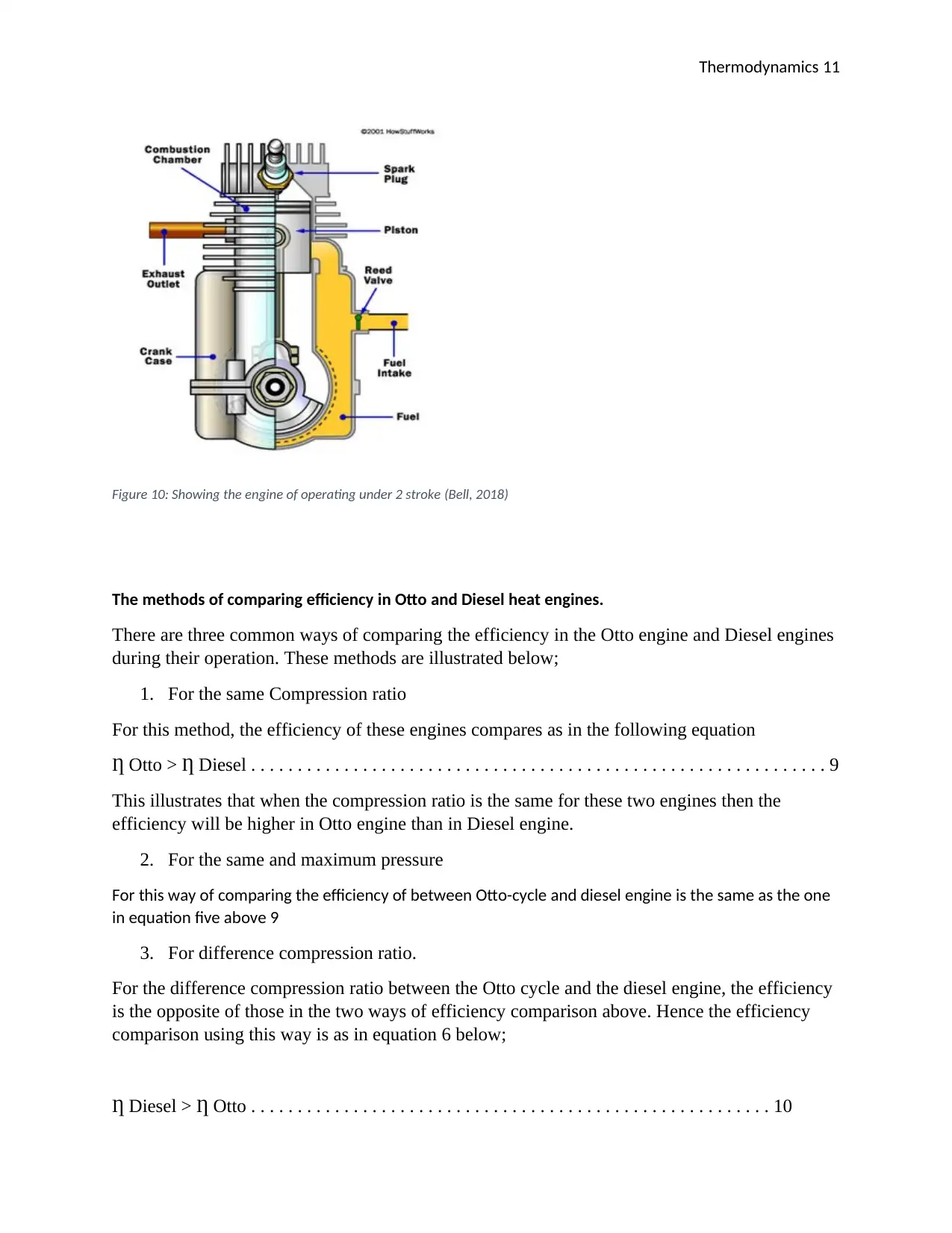
The diagram below illustrates the engine of operating under 2 stroke;
Paraphrase This Document
Need a fresh take? Get an instant paraphrase of this document with our AI Paraphraser
Thermodynamics 11
Figure 10: Showing the engine of operating under 2 stroke (Bell, 2018)
The methods of comparing efficiency in Otto and Diesel heat engines.
There are three common ways of comparing the efficiency in the Otto engine and Diesel engines
during their operation. These methods are illustrated below;
1. For the same Compression ratio
For this method, the efficiency of these engines compares as in the following equation
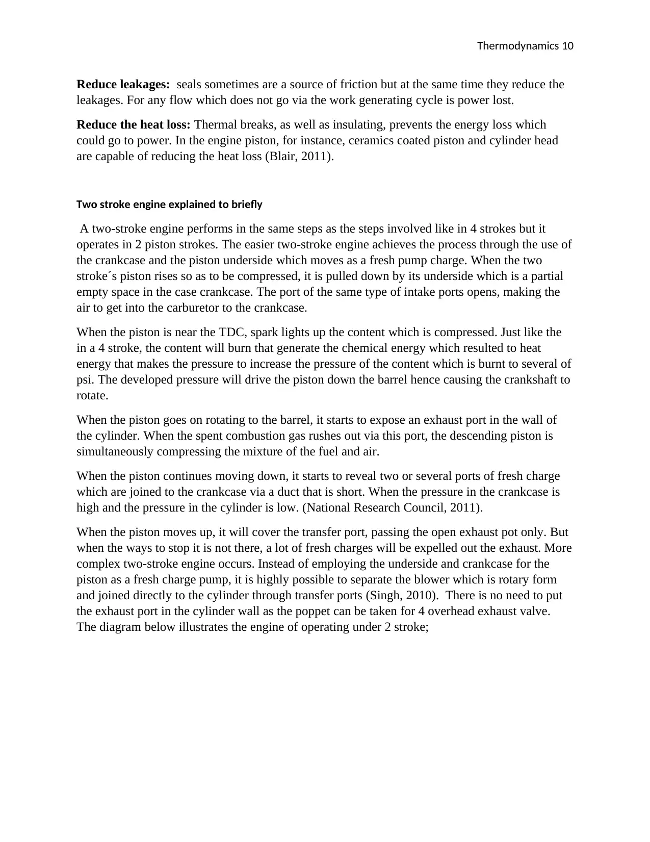
Ƞ Otto ˃ Ƞ Diesel . . . . . . . . . . . . . . . . . . . . . . . . . . . . . . . . . . . . . . . . . . . . . . . . . . . . . . . . . . . . . . 9
This illustrates that when the compression ratio is the same for these two engines then the
efficiency will be higher in Otto engine than in Diesel engine.
2. For the same and maximum pressure
For this way of comparing the efficiency of between Otto-cycle and diesel engine is the same as the one
in equation five above 9
3. For difference compression ratio.
For the difference compression ratio between the Otto cycle and the diesel engine, the efficiency
is the opposite of those in the two ways of efficiency comparison above. Hence the efficiency
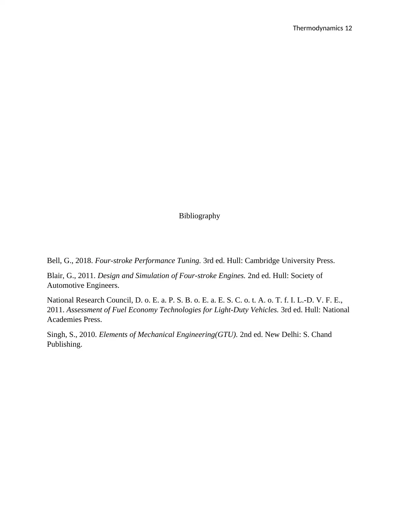
comparison using this way is as in equation 6 below;
Ƞ Diesel ˃ Ƞ Otto . . . . . . . . . . . . . . . . . . . . . . . . . . . . . . . . . . . . . . . . . . . . . . . . . . . . . . . . 10
Thermodynamics 12
Bibliography
Bell, G., 2018. Four-stroke Performance Tuning. 3rd ed. Hull: Cambridge University Press.
Blair, G., 2011. Design and Simulation of Four-stroke Engines. 2nd ed. Hull: Society of
Automotive Engineers.
National Research Council, D. o. E. a. P. S. B. o. E. a. E. S. C. o. t. A. o. T. f. I. L.-D. V. F. E.,
2011. Assessment of Fuel Economy Technologies for Light-Duty Vehicles. 3rd ed. Hull: National
Academies Press.
Singh, S., 2010. Elements of Mechanical Engineering(GTU). 2nd ed. New Delhi: S. Chand
Publishing.
⊘ This is a preview!⊘
Do you want full access?
Subscribe today to unlock all pages.

Trusted by 1+ million students worldwide
1 out of 12
Your All-in-One AI-Powered Toolkit for Academic Success.
+13062052269
info@desklib.com
Available 24*7 on WhatsApp / Email
![[object Object]](/_next/static/media/star-bottom.7253800d.svg)
Unlock your academic potential
Copyright © 2020–2025 A2Z Services. All Rights Reserved. Developed and managed by ZUCOL.


