Ask a question from expert
Aliasing Dithering Image output on Monitor and their Dependencies PDF
12 Pages3943 Words214 Views
Added on 2021-07-01
Aliasing Dithering Image output on Monitor and their Dependencies PDF
Added on 2021-07-01
BookmarkShareRelated Documents
1 | P R A D O S H B A N D Y O P A D H Y A Y ( 1 3 0 4 1 0 2 0 : 0 3 ) TOPICS TO BE COVERED: ALIASING DITHERING IMAGE OUPUT ON MONITOR AND THEIR DEPENDENCIES COLOR MODEL CATHOD RAY TUBE RANDOM SCAN RASTER SCAN INTERLACING Aliasing and anti-aliasing:When displaying images with curves and diagonal lines on the screen one can often find that these lines look jagged instead of smooth A sort of staircase effect replaces what should be smooth curves and diagonal lines, and hence this effect is known as aliasing. Anti-aliasing is a method to counter this staircase effect and restore the smooth appearances of curves and diagonal lines. When the images are displayed on the screen, they have to be projected on a rectangular grid of phosphor dots called pixels. The curves and diagonal lines are also displayed by the pixels which are rectangular block shaped. These blocks cannot accurately follow the smooth curves of the image making them look jagged. The rectangular shape of the phosphor dots however cannot be changed as they are the part of the display device. To rectify these problems anti-aliasing methods reassigns the pixel value in the neighborhood of the aliased areas, thereby creating a gradual toning effect between the curved shapes and the background. This reduces the abrupt color transitions near the aliased features, making them smoother. For anti-aliasing, two approaches are possible: For increasing the resolution to such extent that more pixels become available to coincide with the compound values, i.e. to make the steps small and so many that the staircase begins to look more like sloping ramp. It is an expensive method for reducing aliasing effect. Display two or more pixels around the computed location at varying intensities or by Dithering method.Dithering: Dithering is a technique to improve the appearance of an image having the limited number of colors, like an indexed color image. In this case, the colors which are not available in the palette are simulated by changing the concentration of dots of existing colors. For example, the density of the red dots on a white background can be controlled in various degrees to produce different shades of pink, which may not be available in the palette. Usually when higher bit images are converted to lower bit images, then color band appears because the intermediate shades cannot be represented using smaller bit depth. In this case, using dithering may produce significant improvements the image quality.
2 | P R A D O S H B A N D Y O P A D H Y A Y ( 1 3 0 4 1 0 2 0 : 0 3 ) IMAGE OUTPUT ON MONITOR: Images have a specific resolution which determine the gap between the pixels. Greater the image resolution better usually is the image quality as the pixels are smaller and closer together and therefore capable of displaying a lot more details and supporting finer color gradations. The image pixels are actually strings of binary numbers and therefore may be referred to as logical pixels. When the images are displayed on the monitor however, the logical pixels are directly mapped on to the phosphor dots of the monitor, which may be referred to as physical pixels. DEPENDENCE ON MONITOR RESOLUTION Let us consider an image having dimension 1 inch by inch and a resolution of 72 ppi. Thus the image is made up of 72 logical pixels horizontally and 72 logical pixels vertically. When the image is displayed on 15’’ monitor having resolution of 72 dpi, the on screen size of image is exactly 1 inch by 1 inch, because for the monitor also there are exactly 72 physical pixels per inch. In this case monitor resolution is equal to the image resolution. Let the image be scanned at a higher resolution of 144 ppi and then displayed on the same 15’’ as before. The internal size of the image is still 1 inch by 1 inch but there are 144 logical pixels per inch of the image. The monitor resolution is however unchanged at 72 dpi. When the image is now shown on the screen, the first 72 logical pixels get directly translated to 72 physical pixels on monitor. The next 72 logical pixels then translated to next 72 physical pixels. On the screen now the image takes up 2 inches along the monitor length. Similarly the height of the image also increases to 2 inches along the monitor height. Though the internal representation of the image is still 1 inch by 1 inch, it’s on screen size increases to 2 inch by 2 inch. On other hand if the image resolution decreases to 30 ppi, internally 1 inch of the image will consist 30 logical pixels. When displayed on the same monitor screen, the image now looks smaller because 30 pixels now mapped to the 30 physical pixels occupies only 0.42 inch along the screen. DEPENDENCE ON THE MONITOR SIZE Let us consider a 15’’ monitor which displays 640 pixels horizontally and 480 pixels vertically. An image with pixel dimensions of 640x480 would fill up the entire screen. Now if the image is displayed on 20’’ monitor with 640 by 480 settings, the image would again fill up the entire screen. However because of the larger screen size the absolute size of the image will be larger. This is because the physical pixels of the 20’’ monitor are themselves larger than the phosphor dots of the 15’’ monitor. Though the image will still occupying the same number of pixels, due to the larger pixel size the image may take on a coarser look. Hence displaying low resolution image on larger monitor should be avoided.
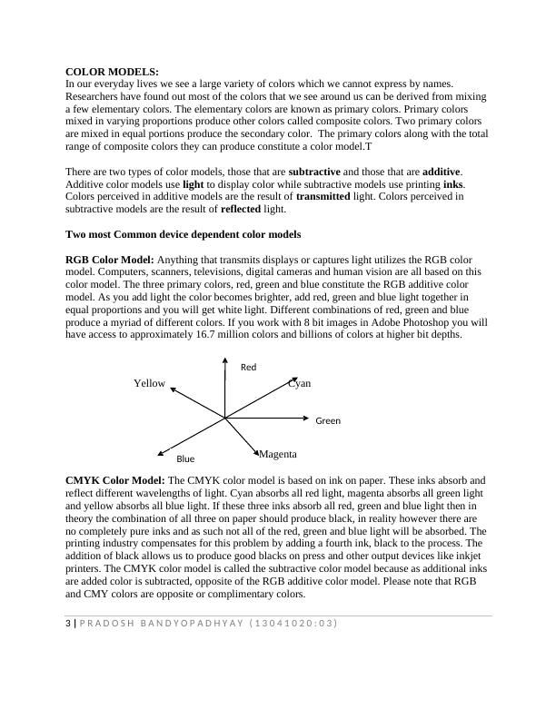
3 | P R A D O S H B A N D Y O P A D H Y A Y ( 1 3 0 4 1 0 2 0 : 0 3 ) COLOR MODELS: In our everyday lives we see a large variety of colors which we cannot express by names. Researchers have found out most of the colors that we see around us can be derived from mixing a few elementary colors. The elementary colors are known as primary colors. Primary colors mixed in varying proportions produce other colors called composite colors. Two primary colors are mixed in equal portions produce the secondary color. The primary colors along with the total range of composite colors they can produce constitute a color model.T There are two types of color models, those that are subtractive and those that are additive. Additive color models use light to display color while subtractive models use printing inks. Colors perceived in additive models are the result of transmitted light. Colors perceived in subtractive models are the result of reflected light. Two most Common device dependent color modelsRGB Color Model: Anything that transmits displays or captures light utilizes the RGB color model. Computers, scanners, televisions, digital cameras and human vision are all based on this color model. The three primary colors, red, green and blue constitute the RGB additive color model. As you add light the color becomes brighter, add red, green and blue light together in equal proportions and you will get white light. Different combinations of red, green and blue produce a myriad of different colors. If you work with 8 bit images in Adobe Photoshop you will have access to approximately 16.7 million colors and billions of colors at higher bit depths. Yellow Cyan Magenta CMYK Color Model: The CMYK color model is based on ink on paper. These inks absorb and reflect different wavelengths of light. Cyan absorbs all red light, magenta absorbs all green light and yellow absorbs all blue light. If these three inks absorb all red, green and blue light then in theory the combination of all three on paper should produce black, in reality however there are no completely pure inks and as such not all of the red, green and blue light will be absorbed. The printing industry compensates for this problem by adding a fourth ink, black to the process. The addition of black allows us to produce good blacks on press and other output devices like inkjet printers. The CMYK color model is called the subtractive color model because as additional inks are added color is subtracted, opposite of the RGB additive color model. Please note that RGB and CMY colors are opposite or complimentary colors. Red Green Blue
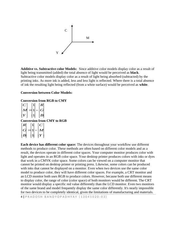
4 | P R A D O S H B A N D Y O P A D H Y A Y ( 1 3 0 4 1 0 2 0 : 0 3 ) C M Y Additive vs. Subtractive color Models: Since additive color models display color as a result of light being transmitted (added) the total absence of light would be perceived as black. Subtractive color models display color as a result of light being absorbed (subtracted) by the printing inks. As more ink is added, less and less light is reflected. Where there is a total absence of ink the resulting light being reflected (from a white surface) would be perceived as white.Conversion between Color Models: Conversion from RGB to CMYBGRYMC111Conversion from CMY to RGBYMCBGR111Each device has different color space: The devices throughout your workflow use different methods to produce color. These methods are often based on different color models and as a result, the devices operate in different color spaces. Your computer monitor produces color with light and operates in an RGB color space. Your desktop printer produces colors with inks or dyes that work in a CMYK color space. Some colors can be viewed on a computer monitor that cannot be printed on desktop printer or printing press. Likewise, some colors can be produced with inks that cannot be displayed on a monitor. Even when two devices use the same color model to produce color, they will have different color spaces. For example, a CRT monitor and an LCD monitor both uses RGB to produce colors. However, because both use different means to display color, the range of color (color space) of both monitors would be different. The CRT monitor would display a specific red value differently than the LCD monitor. Even two monitors of the same brand and model frequently display the same color differently. It's nearly impossible for two devices to be completely identical, given the limitations of manufacturing and materials.
End of preview
Want to access all the pages? Upload your documents or become a member.