Lateral Torsional Buckling in Structures
VerifiedAdded on 2020/05/04
|14
|3321
|158
AI Summary
This assignment delves into the critical topic of lateral torsional buckling in structural engineering. It examines the mechanisms behind this type of failure, highlighting examples of real-world occurrences involving bridges and train tracks. The assignment emphasizes the importance of understanding torsional buckling behavior for safe and reliable structural design.
Contribute Materials
Your contribution can guide someone’s learning journey. Share your
documents today.
Torsional Buckling of Beams 1
RESEARCH PAPER ON THE TORSIONAL BUCKLING OF BEAMS OF CIRCULAR
SECTION
A Research Paper on Torsional Buckling By
Student’s Name
Name of the Professor
Institutional Affiliation
City/State
Year/Month/Day
RESEARCH PAPER ON THE TORSIONAL BUCKLING OF BEAMS OF CIRCULAR
SECTION
A Research Paper on Torsional Buckling By
Student’s Name
Name of the Professor
Institutional Affiliation
City/State
Year/Month/Day
Secure Best Marks with AI Grader
Need help grading? Try our AI Grader for instant feedback on your assignments.
Torsional Buckling of Beams 2
Abstract
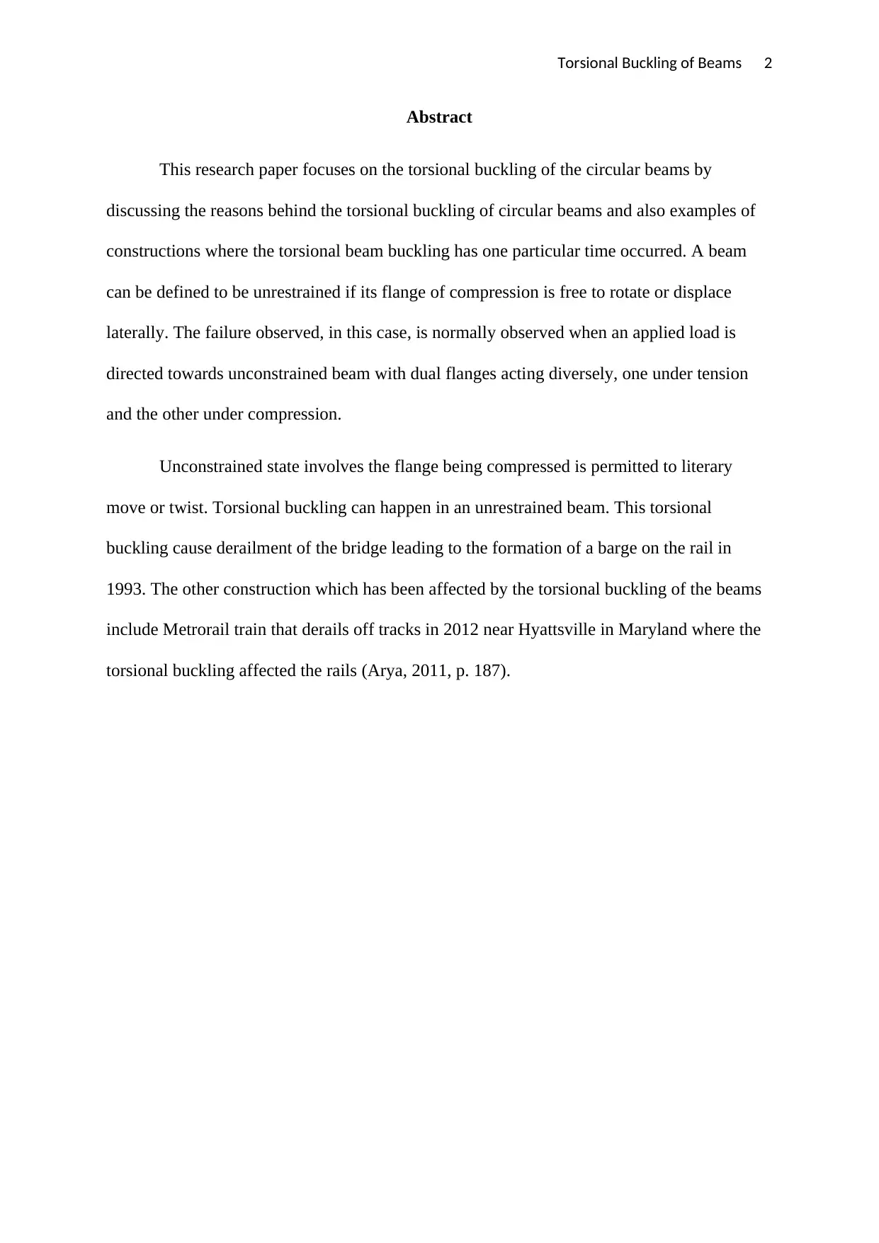
This research paper focuses on the torsional buckling of the circular beams by
discussing the reasons behind the torsional buckling of circular beams and also examples of
constructions where the torsional beam buckling has one particular time occurred. A beam
can be defined to be unrestrained if its flange of compression is free to rotate or displace
laterally. The failure observed, in this case, is normally observed when an applied load is
directed towards unconstrained beam with dual flanges acting diversely, one under tension
and the other under compression.
Unconstrained state involves the flange being compressed is permitted to literary
move or twist. Torsional buckling can happen in an unrestrained beam. This torsional
buckling cause derailment of the bridge leading to the formation of a barge on the rail in
1993. The other construction which has been affected by the torsional buckling of the beams
include Metrorail train that derails off tracks in 2012 near Hyattsville in Maryland where the
torsional buckling affected the rails (Arya, 2011, p. 187).
Torsional Buckling of Beams 3
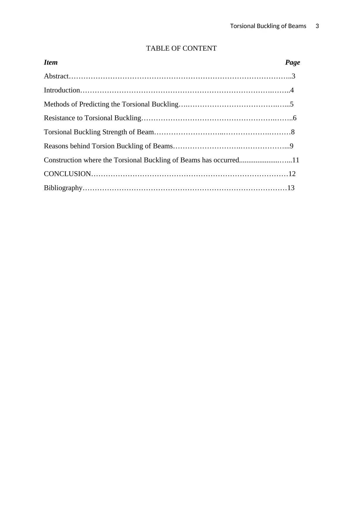
TABLE OF CONTENT
Item Page
Abstract………………………………………………………………………………..3
Introduction…………………………………………………………………….……..4
Methods of Predicting the Torsional Buckling….……………………………….…...5
Resistance to Torsional Buckling……………………………………………….……..6
Torsional Buckling Strength of Beam………………………..……………….………8
Reasons behind Torsion Buckling of Beams……………………….………………...9
Construction where the Torsional Buckling of Beams has occurred......................…...11
CONCLUSION………………………………………………………………………12
Bibliography…………………………………………………………………………13
Torsional Buckling of Beams 4
INTRODUCTION
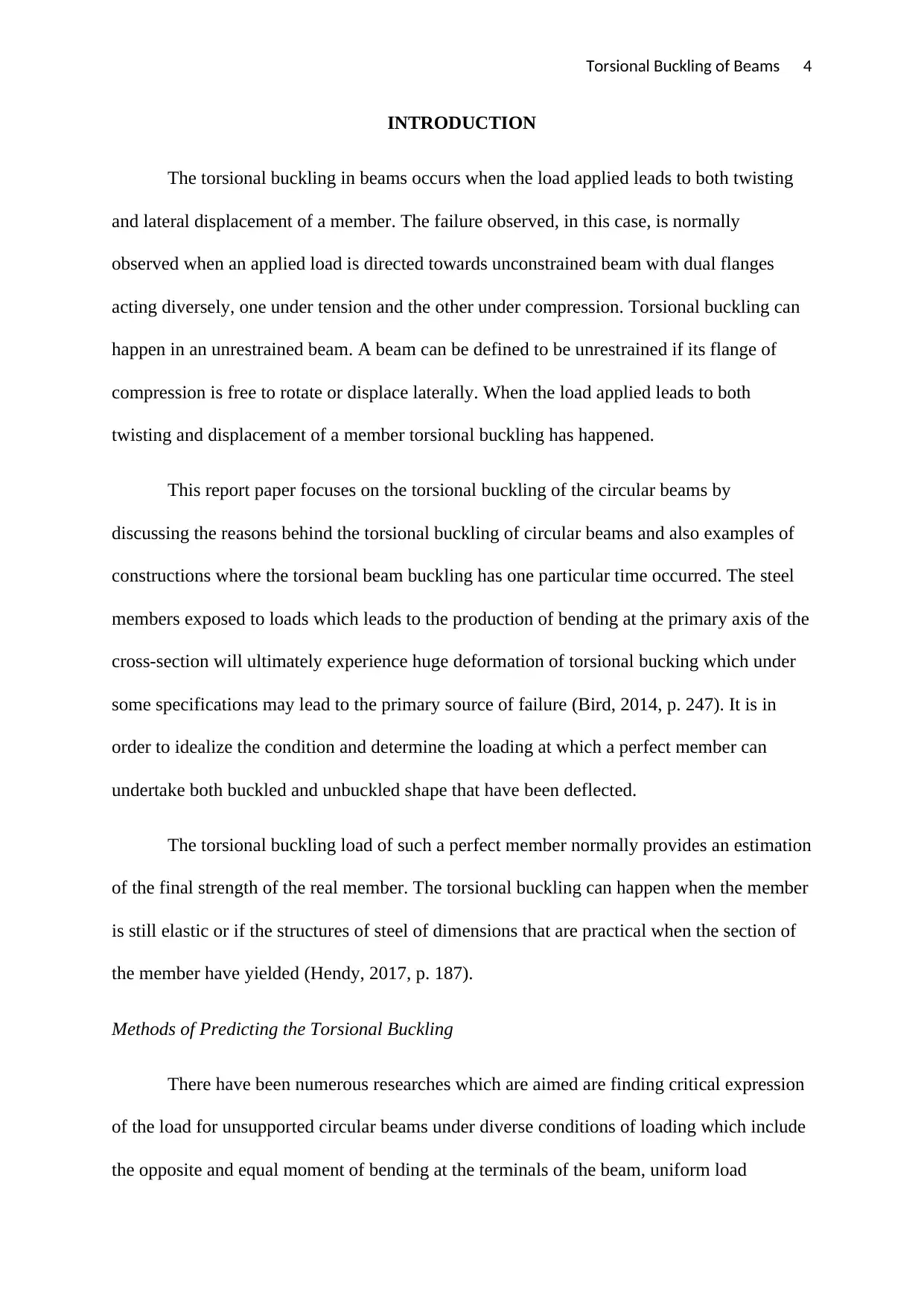
The torsional buckling in beams occurs when the load applied leads to both twisting
and lateral displacement of a member. The failure observed, in this case, is normally
observed when an applied load is directed towards unconstrained beam with dual flanges
acting diversely, one under tension and the other under compression. Torsional buckling can
happen in an unrestrained beam. A beam can be defined to be unrestrained if its flange of
compression is free to rotate or displace laterally. When the load applied leads to both
twisting and displacement of a member torsional buckling has happened.
This report paper focuses on the torsional buckling of the circular beams by
discussing the reasons behind the torsional buckling of circular beams and also examples of
constructions where the torsional beam buckling has one particular time occurred. The steel
members exposed to loads which leads to the production of bending at the primary axis of the
cross-section will ultimately experience huge deformation of torsional bucking which under
some specifications may lead to the primary source of failure (Bird, 2014, p. 247). It is in
order to idealize the condition and determine the loading at which a perfect member can
undertake both buckled and unbuckled shape that have been deflected.
The torsional buckling load of such a perfect member normally provides an estimation
of the final strength of the real member. The torsional buckling can happen when the member
is still elastic or if the structures of steel of dimensions that are practical when the section of
the member have yielded (Hendy, 2017, p. 187).
Methods of Predicting the Torsional Buckling
There have been numerous researches which are aimed are finding critical expression
of the load for unsupported circular beams under diverse conditions of loading which include
the opposite and equal moment of bending at the terminals of the beam, uniform load
Secure Best Marks with AI Grader
Need help grading? Try our AI Grader for instant feedback on your assignments.
Torsional Buckling of Beams 5
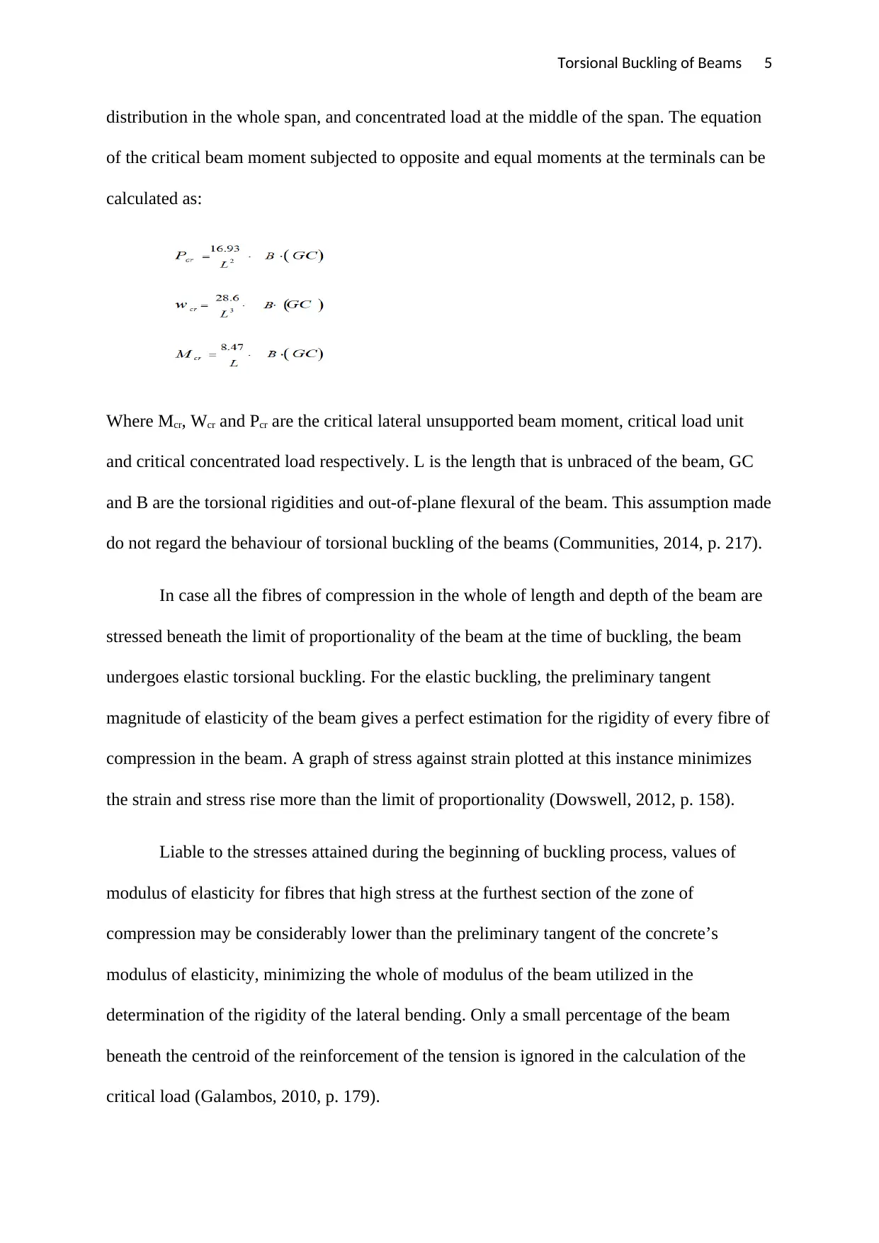
distribution in the whole span, and concentrated load at the middle of the span. The equation
of the critical beam moment subjected to opposite and equal moments at the terminals can be
calculated as:
Where Mcr, Wcr and Pcr are the critical lateral unsupported beam moment, critical load unit
and critical concentrated load respectively. L is the length that is unbraced of the beam, GC
and B are the torsional rigidities and out-of-plane flexural of the beam. This assumption made
do not regard the behaviour of torsional buckling of the beams (Communities, 2014, p. 217).
In case all the fibres of compression in the whole of length and depth of the beam are
stressed beneath the limit of proportionality of the beam at the time of buckling, the beam
undergoes elastic torsional buckling. For the elastic buckling, the preliminary tangent
magnitude of elasticity of the beam gives a perfect estimation for the rigidity of every fibre of
compression in the beam. A graph of stress against strain plotted at this instance minimizes
the strain and stress rise more than the limit of proportionality (Dowswell, 2012, p. 158).
Liable to the stresses attained during the beginning of buckling process, values of
modulus of elasticity for fibres that high stress at the furthest section of the zone of
compression may be considerably lower than the preliminary tangent of the concrete’s
modulus of elasticity, minimizing the whole of modulus of the beam utilized in the
determination of the rigidity of the lateral bending. Only a small percentage of the beam
beneath the centroid of the reinforcement of the tension is ignored in the calculation of the
critical load (Galambos, 2010, p. 179).
Torsional Buckling of Beams 6
Hence, the extension of the flexural cracks in the region of tension should be
established well to evaluate the portion of the beam giving buckling against rigidity. The
utilization of d in the calculation of the critical load may overestimate the portion of the beam
efficient in resistance to lateral buckling at the moment of failure (Gupta, 2014, p. 194).
Resistance to Torsional Buckling
The section of the beam efficient in resisting the torsional buckling can be evaluated
according to the distribution of strain in the section and in the span of the beam at the
buckling’s onset. The fibres in the zone of tension strained beyond the strain of cracking of
concrete are not put into the contemplation in the calculation of the critical load (Hassan,
2015, p. 184). According to the levels of moment attained before buckling process, the
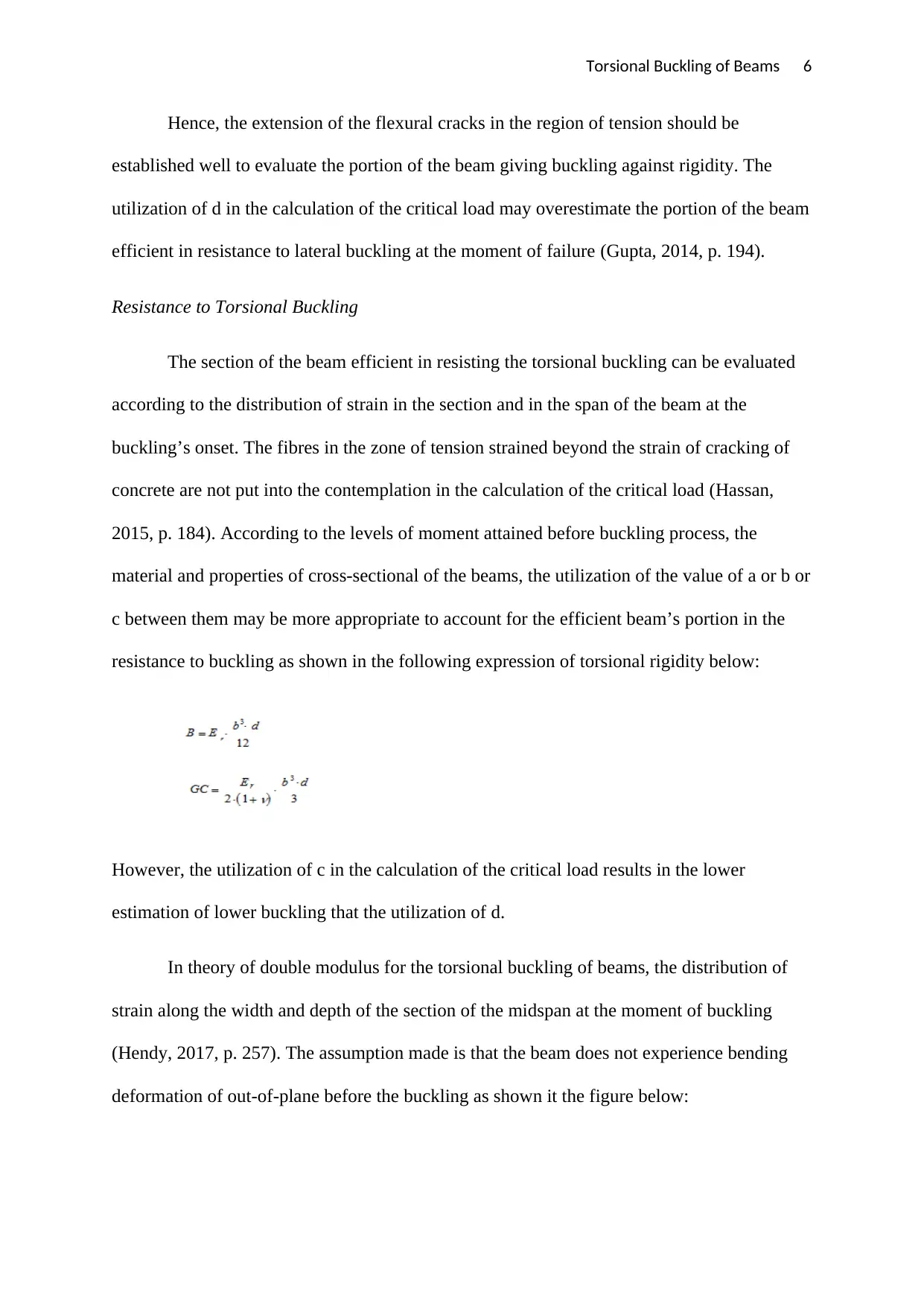
material and properties of cross-sectional of the beams, the utilization of the value of a or b or
c between them may be more appropriate to account for the efficient beam’s portion in the
resistance to buckling as shown in the following expression of torsional rigidity below:
However, the utilization of c in the calculation of the critical load results in the lower
estimation of lower buckling that the utilization of d.
In theory of double modulus for the torsional buckling of beams, the distribution of
strain along the width and depth of the section of the midspan at the moment of buckling
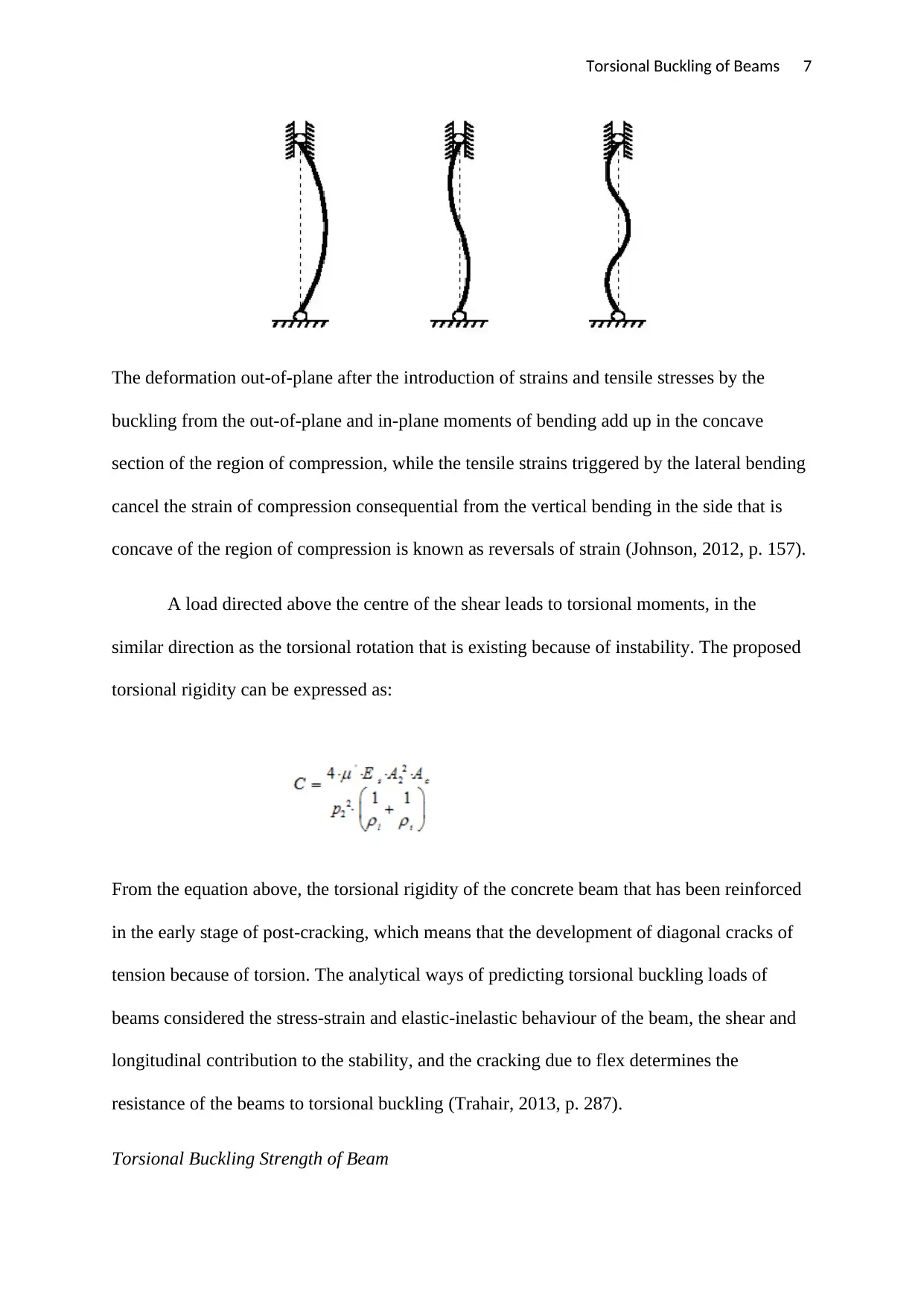
(Hendy, 2017, p. 257). The assumption made is that the beam does not experience bending
deformation of out-of-plane before the buckling as shown it the figure below:
Torsional Buckling of Beams 7
The deformation out-of-plane after the introduction of strains and tensile stresses by the
buckling from the out-of-plane and in-plane moments of bending add up in the concave
section of the region of compression, while the tensile strains triggered by the lateral bending
cancel the strain of compression consequential from the vertical bending in the side that is
concave of the region of compression is known as reversals of strain (Johnson, 2012, p. 157).
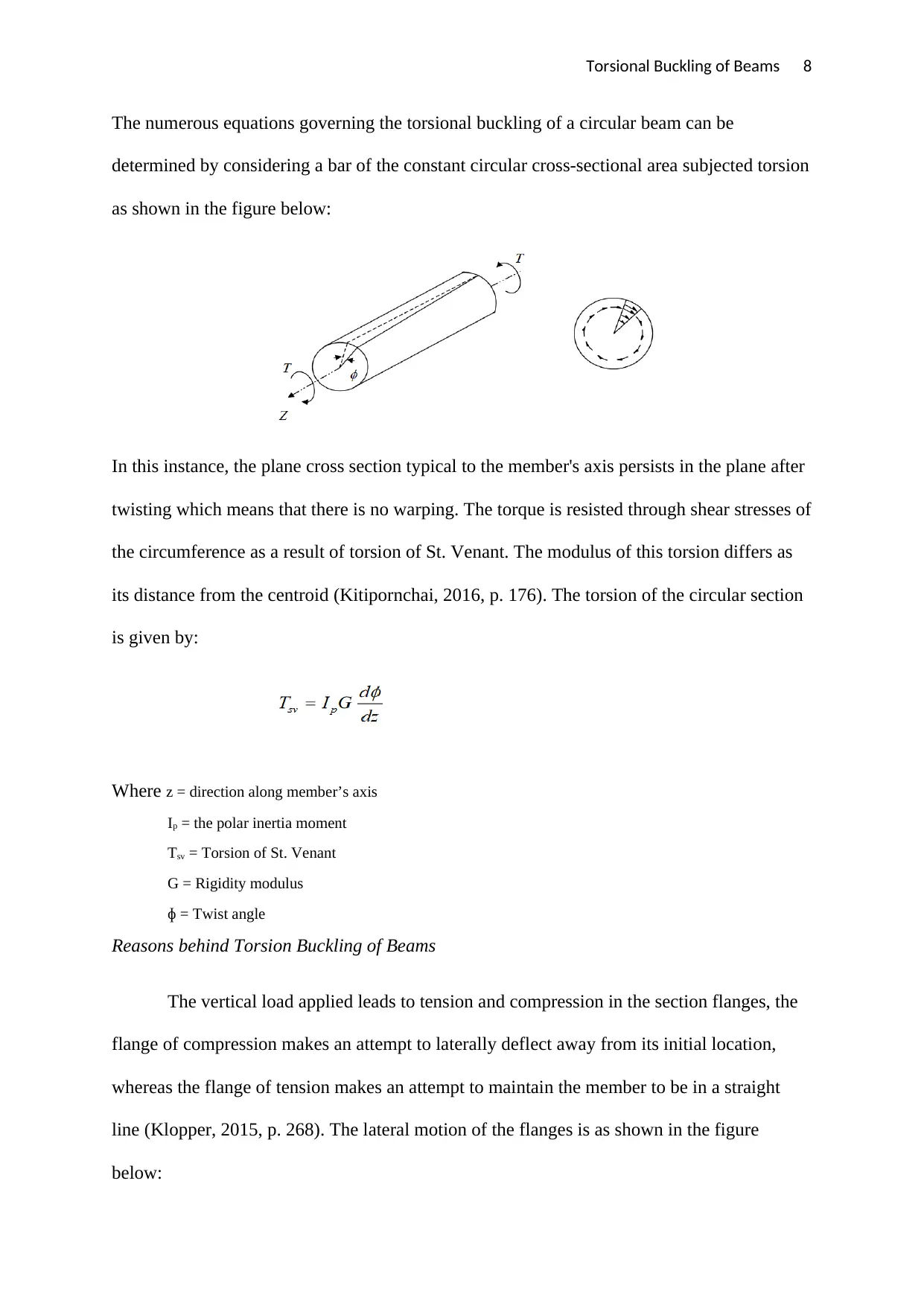
A load directed above the centre of the shear leads to torsional moments, in the
similar direction as the torsional rotation that is existing because of instability. The proposed
torsional rigidity can be expressed as:
From the equation above, the torsional rigidity of the concrete beam that has been reinforced
in the early stage of post-cracking, which means that the development of diagonal cracks of
tension because of torsion. The analytical ways of predicting torsional buckling loads of
beams considered the stress-strain and elastic-inelastic behaviour of the beam, the shear and
longitudinal contribution to the stability, and the cracking due to flex determines the
resistance of the beams to torsional buckling (Trahair, 2013, p. 287).
Torsional Buckling Strength of Beam
Paraphrase This Document
Need a fresh take? Get an instant paraphrase of this document with our AI Paraphraser
Torsional Buckling of Beams 8
The numerous equations governing the torsional buckling of a circular beam can be
determined by considering a bar of the constant circular cross-sectional area subjected torsion
as shown in the figure below:
In this instance, the plane cross section typical to the member's axis persists in the plane after
twisting which means that there is no warping. The torque is resisted through shear stresses of
the circumference as a result of torsion of St. Venant. The modulus of this torsion differs as
its distance from the centroid (Kitipornchai, 2016, p. 176). The torsion of the circular section
is given by:
Where z = direction along member’s axis
Ip = the polar inertia moment
Tsv = Torsion of St. Venant
G = Rigidity modulus
ɸ = Twist angle
Reasons behind Torsion Buckling of Beams
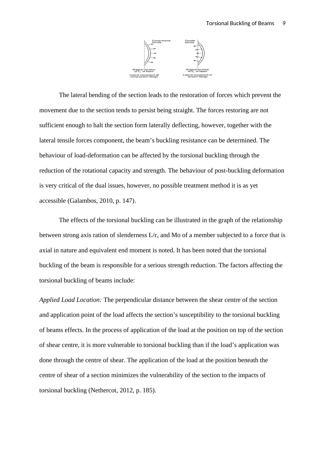
The vertical load applied leads to tension and compression in the section flanges, the
flange of compression makes an attempt to laterally deflect away from its initial location,
whereas the flange of tension makes an attempt to maintain the member to be in a straight
line (Klopper, 2015, p. 268). The lateral motion of the flanges is as shown in the figure
below:
Torsional Buckling of Beams 9
The lateral bending of the section leads to the restoration of forces which prevent the
movement due to the section tends to persist being straight. The forces restoring are not
sufficient enough to halt the section form laterally deflecting, however, together with the
lateral tensile forces component, the beam’s buckling resistance can be determined. The
behaviour of load-deformation can be affected by the torsional buckling through the
reduction of the rotational capacity and strength. The behaviour of post-buckling deformation
is very critical of the dual issues, however, no possible treatment method it is as yet
accessible (Galambos, 2010, p. 147).
The effects of the torsional buckling can be illustrated in the graph of the relationship
between strong axis ration of slenderness L/rx and Mo of a member subjected to a force that is
axial in nature and equivalent end moment is noted. It has been noted that the torsional
buckling of the beam is responsible for a serious strength reduction. The factors affecting the
torsional buckling of beams include:
Applied Load Location: The perpendicular distance between the shear centre of the section
and application point of the load affects the section’s susceptibility to the torsional buckling
of beams effects. In the process of application of the load at the position on top of the section
of shear centre, it is more vulnerable to torsional buckling than if the load’s application was
done through the centre of shear. The application of the load at the position beneath the
centre of shear of a section minimizes the vulnerability of the section to the impacts of
torsional buckling (Nethercot, 2012, p. 185).
Torsional Buckling of Beams 10
The application of the load above the centre of shear is referred to as destabilizing load, with
applied loads below or at the centre of shear known as non-destabilising loads. The impacts
of load destabilization are considered by the utilization of effective lengths provided, where
the lengths that are effective are longer for loads destabilization compared to the loads that
are non-destabilizing.
Applied Bending Moment Shape: The resistance of buckling for a section issue to a constant
distribution of bending moment along its length is less than the resistance of buckling gotten
for the similar section subjected to the diverse distribution of bending moment. These factors
are involved in the guidance of the design to enable for the impacts of diverse distribution of
bending moment (Coutie, 2017, p. 219).
Conditions of End Support: The conditions of the end support considered during the growth
of primary theory for the moment of buckling are equal to web cleats which halt the web
from deflecting twistingly and laterally. For the conditions of end support where extra
confines are provided to the section the moment of buckling increases, with the moment of
buckling reducing the support at the terminal which provides less restraint to the section.
Cross-sectional Size: The resultant interaction strength curves are not sensitive to the
variations in the size of the cross-section for shapes of wide-flange that have been rolled, and
a single set of curves for any specified value of the ultimate ration of the moment is enough.
It is possible that the torsional buckling will be near the final strength even before the cross-
over for any section (Morchi, 2016, p. 268).
Level of Yield Stress: It has been proved that for a common straightening and rolling
processes, the distribution of residual stress does not significantly vary with the increase in
the yield stress. The elastic section of the beam in the level of yield stress shifts to the left the
Secure Best Marks with AI Grader
Need help grading? Try our AI Grader for instant feedback on your assignments.
Torsional Buckling of Beams 11
elastic torsional buckling. This shows that at higher strength member, elastic torsional
buckling would happen at a length that is shorter than that of the member.
Residual Stress Influence: The major influence of increasing the residual level of residual
stress is the reduction in the value of moment applied at which the limit of elastic is attained.
In the range of inelastic, the relationship between the slenderness ratio and moment applied
are approximately linear for n-both the levels of residual stress. Therefore, increasing the
pattern of residual stress minimizes the member’s elastic limit moment and hence causing a
minimization in the strength in the range of inelastic (Miranda, 2011, p. 174).
Constructions where the Torsional Buckling of Beams has occurred
During the building of the bridge of steel girder, the girders to be positioned are
collected by the crane. It is the responsibility of the contractor to place the girder without any
damage. During the construction of this bridge, the girder was positioned by the two cranes
concurrently picking the girders up from both ends. The build-up plate-girders weighed about
96,000 pounds, 7.5 feet deep, and 197 feet long (Lue, 2013, p. 235). Due to such a long
length under consideration, the torsional buckling occurred. During the process of lifting the
first girder, it was likely that the failure of the girder was imminent as the span at the middle
started bowing over which is the initial sign of buckling. Previously, the major intentions of
this projects were the determination of necessary forces to adequately stiffen the flange
compression of the girder hence preventing torsional buckling (Klopper, 2015, p. 197).
The construction of Washington Metro in Washington area of US in 1976 faced the
torsional buckling during its operations. In 1982, the Washington Metro faced derailment at
the crossover of the Triangle station which was triggered by the torsional clasping of the rails
leading to the car sliding off the track and hitting the tunnel. The Amtrak passenger railroad
service which was constructed in 1971 and is situated in the US also faced the problem of
Torsional Buckling of Beams 12
torsional buckling in the past. This torsional buckling cause derailment of the bridge leading
to the formation of a barge on the rail in 1993. The other construction which has been
affected by the torsional buckling of the beams include Metrorail train that derails off tracks
in 2012 near Hyattsville in Maryland where the torsional buckling affected the rails (Klopper,
2015, p. 213).
Conclusion
This research paper is about the torsional buckling of beams. The torsional buckling
in beams occurs when the load applied leads to both twisting and lateral displacement of a
member. This report paper focuses on the torsional buckling of the circular beams by
discussing the reasons behind the torsional buckling of circular beams and also examples of
constructions where the torsional beam buckling has one particular time occurred. This
torsional buckling cause derailment of the bridge leading to the formation of the barge on the
rail in 1993. The other construction which has been affected by the torsional buckling of the
beams include Metrorail train that derails off tracks in 2012 near Hyattsville in Maryland
where the torsional buckling affected the rails.
Torsional Buckling of Beams 13
Bibliography
Arya C., 2011. Design of Structural Elements: Concrete, Steelwork, Masonry and Timber Designs to
British Standards and Eurocodes, Second Edition. Pretoria: CRC Press.
Bird R., 2014. Lateral Torsional Buckling of Cranked Beams. Perth: Queensland Institute of
Technology.
Hendy, R, 2017. Designers' Guide to EN 1994-2: Eurocode 4: Design of Steel and Composite
Structures: Part 2: General Rules and Rules for Bridge. London: Thomas Telford.
Chen, W, 2016. Theory of Beam-Columns, Volume 1: In-Plane Behavior and Design. Berlin: J. Ross
Publishing.
Communities, E., 2014. Lateral Torsional Buckling in Steel and Composite Beams. London: Office for
Official Publications of the European Communities.
Dowswell, R, 2012. Lateral-torsional Buckling of Wide Flange Cantilever Beams. Washington DC: the
University of Alabama at Birmingham.
Galambos, T, 2010. Guide to Stability Design Criteria for Metal Structures. Toledo: John Wiley & Sons.
George J, 2015. Fundamentals of Structural Stability. Michigan: Butterworth-Heinemann.
Gupta, P., 2014. Lateral Torsional Buckling of Nonprismatic Indeterminate Beams. Toledo: University
of Kentucky.
Hassan, R., 2015. Distortion Lateral Torsional Buckling Analysis for Beams of Wide Flange Cross-
sections. Paris: IEEE.
Johnson, R, 2012. Designers' Handbook to Eurocode 4: 1. Design of composite steel and concrete
structures. Moscow: Thomas Telford.
Kalkan, I., 2013. Lateral Torsional Buckling of Rectangular Reinforced Concrete Beams. Paris: Georgia
Institute of Technology.
Klopper, J, 2015. The Lateral Torsional Buckling Strength of Hot-rolled 3CR12 Beams. London: Rand
Afrikaans University.
Lue, D, 2013. Lateral-torsional Buckling of a Rolled Wide Flange Beam with Channel Cap. Florida:
University of Florida.
Miranda, C, 2011. The Occurrence of Lateral-torsional Buckling in Beam-columns. Ohio: Ohio State
University.
Morchi, S, 2016. Flexural-torsional Buckling of Intersecting Inter-connected Beams. Moscow: the
University of Wisconsin - Madison.
Nethercot, D, 2012. Lateral-torsional Buckling of Beams. Colorado: Department of Civil and
Structural Engineering.
Coates, M, 2017. Structural Analysis. Melbourne: CRC Press.
Kitipornchai, C, 2016. Flexural-torsional buckling of monosymmetric beam-columns/tie-beams.
London: University of Queensland.
Paraphrase This Document
Need a fresh take? Get an instant paraphrase of this document with our AI Paraphraser
Torsional Buckling of Beams 14
Trahair, N, 2013. Flexural-Torsional Buckling of Structures. Colorado: CRC Press.
Trahair, N, 2013. Flexural-Torsional Buckling of Structures. Colorado: CRC Press.
1 out of 14
Related Documents
Your All-in-One AI-Powered Toolkit for Academic Success.
+13062052269
info@desklib.com
Available 24*7 on WhatsApp / Email
![[object Object]](/_next/static/media/star-bottom.7253800d.svg)
Unlock your academic potential
© 2024 | Zucol Services PVT LTD | All rights reserved.


