Tour and Transport System | Report
Added on 2022-09-09
12 Pages2483 Words11 Views
Running head: TOUR AND TRANSPORT SYSTEM
TOUR AND TRANSPORT SYSTEM
Name of the student:
Name of the university:
Author Note:
TOUR AND TRANSPORT SYSTEM
Name of the student:
Name of the university:
Author Note:

TOUR AND TRANSPORT SYSTEM1
Table of Contents
1. Use-Case Realization.............................................................................................................2
1.1. Analysis Class Diagram..................................................................................................2
1.1.1. Description of Class Diagram..................................................................................2
1.1.2. Class Diagram View................................................................................................3
1.1.3. Class Diagram Analysis...........................................................................................3
1.2. Communication Diagram................................................................................................4
1.2.1. Communication Diagram Description.....................................................................4
1.2.2. Communication Diagram View...............................................................................4
1.2.3. Analysis of Communication Diagram......................................................................5
2. Sequence Diagram.................................................................................................................5
2.1. Sequence Diagram Description.......................................................................................5
2.2. Sequence Diagram View.................................................................................................6
2.3. Analysis of Sequence Diagram.......................................................................................7
3. Evaluation of CASE Tool......................................................................................................7
3.1. Description of CASE Tool..............................................................................................7
3.2. Role of Analyst supported by CASE Tool......................................................................8
3.3. Role of Analyst supported by UML Modelling..............................................................9
References................................................................................................................................10
TOUR AND TRANSPORT SYSTEM2
1. Use-Case Realization
1.1. Analysis Class Diagram
1.1.1. Description of Class Diagram
The objects and the interrelationship between them is defined in the Class Diagram,
which is classified as one of the types of the structural diagrams of Unified Modelling
Language. The components also define their own functionalities in the system and state what
services the user can get from the system (Sulaiman, Ahmad and Ahmad 2019). Each
component of the class diagram that are known as objects has certain attributes, signals and
operations associated with it. Class diagrams helps in understanding the behaviour of a
system and explain the operations between them. Software developers use the class diagrams
to determine the objects and define their attributes while writing codes for a program to
develop a system.
TOUR AND TRANSPORT SYSTEM3
1.1.2. Class Diagram View
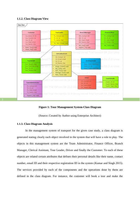
Figure 1: Tour Management System-Class Diagram
(Source: Created by Author using Enterprise Architect)
1.1.3. Class Diagram Analysis
In the management system of transport for the given case study, a class diagram is
generated stating clearly each object involved in the system that will have a role to play. The
objects in this management system are the Team Administrator, Finance Officer, Branch
Manager, Clerical Assistant, Tour Leader, Driver and finally the Customer. To each of these
objects are related certain attributes that defines their personal details like their name, contact
number, email ID and their respective registration ID in the system (Kumar and Singh 2015).
The services provided by each of the components and the operations done by them are
defined in the class diagram. For instance, the customer will book a tour and make the
1.1.2. Class Diagram View
Figure 1: Tour Management System-Class Diagram
(Source: Created by Author using Enterprise Architect)
1.1.3. Class Diagram Analysis
In the management system of transport for the given case study, a class diagram is
generated stating clearly each object involved in the system that will have a role to play. The
objects in this management system are the Team Administrator, Finance Officer, Branch
Manager, Clerical Assistant, Tour Leader, Driver and finally the Customer. To each of these
objects are related certain attributes that defines their personal details like their name, contact
number, email ID and their respective registration ID in the system (Kumar and Singh 2015).
The services provided by each of the components and the operations done by them are
defined in the class diagram. For instance, the customer will book a tour and make the
End of preview
Want to access all the pages? Upload your documents or become a member.
Related Documents
System Analysis & Designlg...
|8
|1645
|496
IMAT5205 Structural And Behavioral Diagramslg...
|13
|2182
|25
SQL Structured Query Language Databaselg...
|9
|990
|413
Analysis UML class diagramlg...
|9
|1767
|11
System Analysis and Designlg...
|11
|2248
|378
System Analysis and Designlg...
|11
|2261
|430