University Assignment: IMAT5205 - Tour Management System Design
VerifiedAdded on 2022/09/03
|12
|2087
|33
Report
AI Summary
This report details the design and analysis of a Tour Management System, undertaken as part of the IMAT5205 Systems Analysis and Design module. The report begins with an analysis class diagram, representing the static framework of the system, illustrating classes, interfaces, relationships, and associations. It then presents a communication diagram, also known as a collaboration diagram, which visualizes interactions between objects through messages. A sequence diagram is also included, depicting the sequential interaction of objects and actors, such as the clerical assistant, tour driver, and tour leader. The report concludes with an evaluation of the design process, emphasizing the use of Computer-Aided Software Engineering (CASE) tools. The evaluation highlights the benefits of CASE tools in creating UML diagrams, improving design accuracy, and enhancing the overall efficiency of the system design lifecycle. The student has used CASE tools for constructing the diagrams of World-Wide Tours. The diagrams properly designed and structured and aligning the designs of class, sequence and communication was very easy due to use of CASE tool.

Running head: TOUR MANAGEMENT SYSTEM DESIGN
Tour Management System Design
Name of the Student
Name of the University
Author’s note:
Tour Management System Design
Name of the Student
Name of the University
Author’s note:
Paraphrase This Document
Need a fresh take? Get an instant paraphrase of this document with our AI Paraphraser
1TOUR MANAGEMENT SYSTEM DESIGN
Table of Contents
Part 1................................................................................................................................................2
1.1 Analysis Class Diagram:........................................................................................................2
1.2 Communication Diagram:.....................................................................................................3
Part 2................................................................................................................................................5
2.1 Sequence Diagram:................................................................................................................5
Part 3................................................................................................................................................6
3.1 Evaluation:.............................................................................................................................6
Bibliography:...................................................................................................................................9
2TOUR MANAGEMENT SYSTEM DESIGN
Part 1
1.1 Analysis Class Diagram:
Class diagrams is considered as the main building blocks of the object oriented models
and methods. Class diagram represent the static framework of the system. The class diagram can
show the classes, interfaces, relationships, collaboration and associated. Standardized UML is
used in class diagram (Ibrahim et al. 2018). As Object oriented programming application is
based on the building blocks generated using classes, the proposed class diagram must have
proper structure for representing relationships, classes, associations, inheritance, polymorphism
and abstraction in the context of OOP. It is essential for describing the static relationship and
several kinds of objects within application.
⊘ This is a preview!⊘
Do you want full access?
Subscribe today to unlock all pages.

Trusted by 1+ million students worldwide
3TOUR MANAGEMENT SYSTEM DESIGN
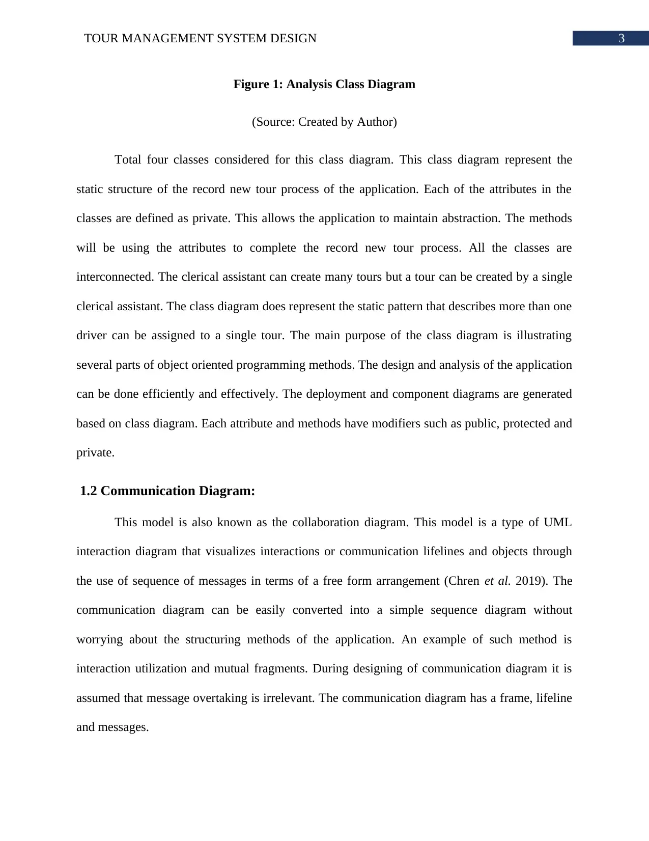
Figure 1: Analysis Class Diagram
(Source: Created by Author)
Total four classes considered for this class diagram. This class diagram represent the
static structure of the record new tour process of the application. Each of the attributes in the
classes are defined as private. This allows the application to maintain abstraction. The methods
will be using the attributes to complete the record new tour process. All the classes are
interconnected. The clerical assistant can create many tours but a tour can be created by a single
clerical assistant. The class diagram does represent the static pattern that describes more than one
driver can be assigned to a single tour. The main purpose of the class diagram is illustrating
several parts of object oriented programming methods. The design and analysis of the application
can be done efficiently and effectively. The deployment and component diagrams are generated
based on class diagram. Each attribute and methods have modifiers such as public, protected and
private.
1.2 Communication Diagram:
This model is also known as the collaboration diagram. This model is a type of UML
interaction diagram that visualizes interactions or communication lifelines and objects through
the use of sequence of messages in terms of a free form arrangement (Chren et al. 2019). The
communication diagram can be easily converted into a simple sequence diagram without
worrying about the structuring methods of the application. An example of such method is
interaction utilization and mutual fragments. During designing of communication diagram it is
assumed that message overtaking is irrelevant. The communication diagram has a frame, lifeline
and messages.
Paraphrase This Document
Need a fresh take? Get an instant paraphrase of this document with our AI Paraphraser
4TOUR MANAGEMENT SYSTEM DESIGN
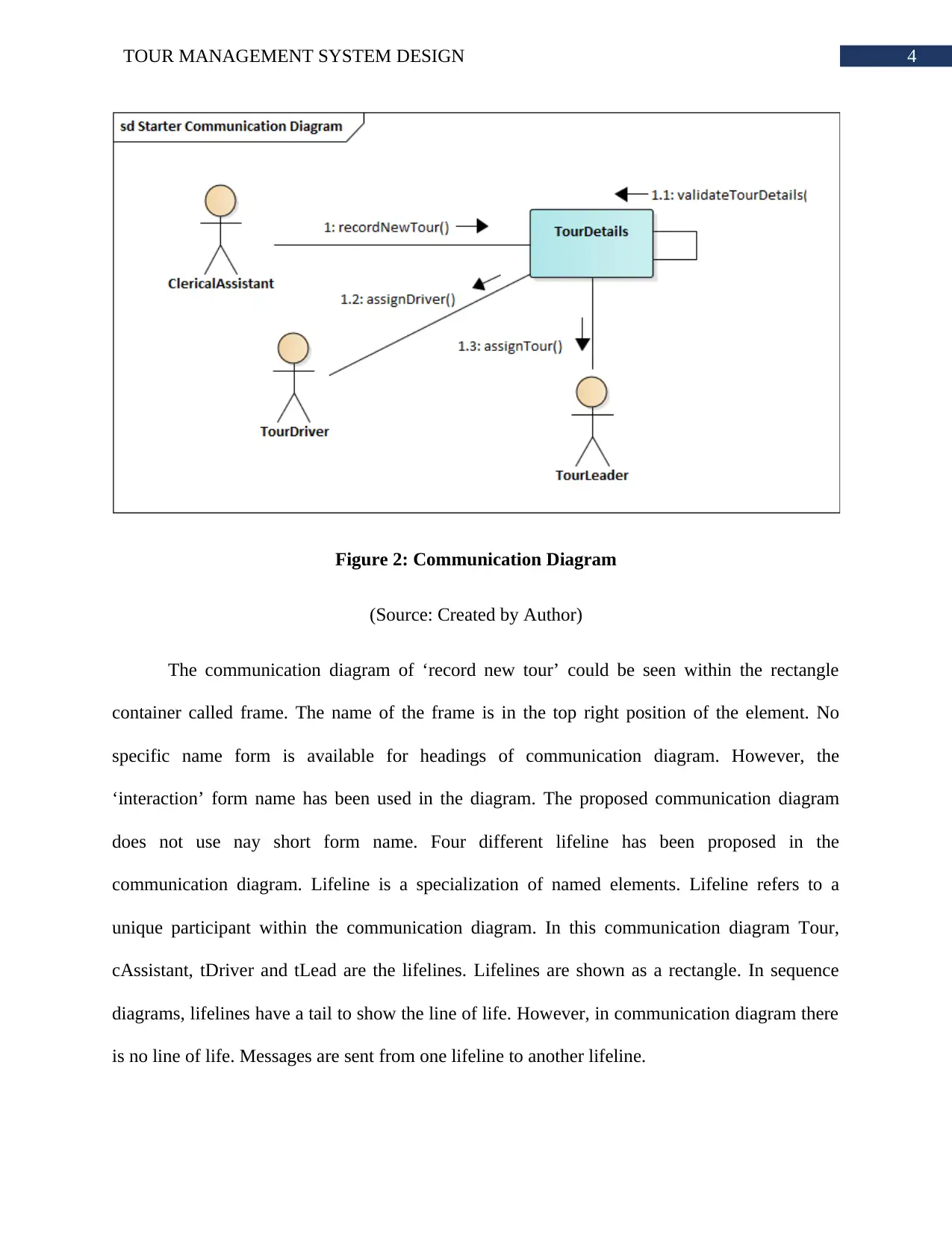
Figure 2: Communication Diagram
(Source: Created by Author)
The communication diagram of ‘record new tour’ could be seen within the rectangle
container called frame. The name of the frame is in the top right position of the element. No
specific name form is available for headings of communication diagram. However, the
‘interaction’ form name has been used in the diagram. The proposed communication diagram
does not use nay short form name. Four different lifeline has been proposed in the
communication diagram. Lifeline is a specialization of named elements. Lifeline refers to a
unique participant within the communication diagram. In this communication diagram Tour,
cAssistant, tDriver and tLead are the lifelines. Lifelines are shown as a rectangle. In sequence
diagrams, lifelines have a tail to show the line of life. However, in communication diagram there
is no line of life. Messages are sent from one lifeline to another lifeline.

5TOUR MANAGEMENT SYSTEM DESIGN
Part 2
2.1 Sequence Diagram:
The sequence diagram illustrates the connection among the objects in form of sequential
manner. This implies that the interaction between the objects happen in a specific order.
Sequence diagram is also called event scenarios or event diagrams (Karim et al. 2017). The
sequence diagrams provide a behavioral pattern of the application that illustrates in which order
the system functions happen and object connection occurs. Sequence diagram plays an important
role in collecting and analyzing the requirements of a new system. Sequence diagrams are
consisted of actors, lifeline, objects and messages (Khurana, Chhillar and Chhillar 2016). The
communication between objects and actors are proposed through messages in the sequence
model.
⊘ This is a preview!⊘
Do you want full access?
Subscribe today to unlock all pages.

Trusted by 1+ million students worldwide
6TOUR MANAGEMENT SYSTEM DESIGN
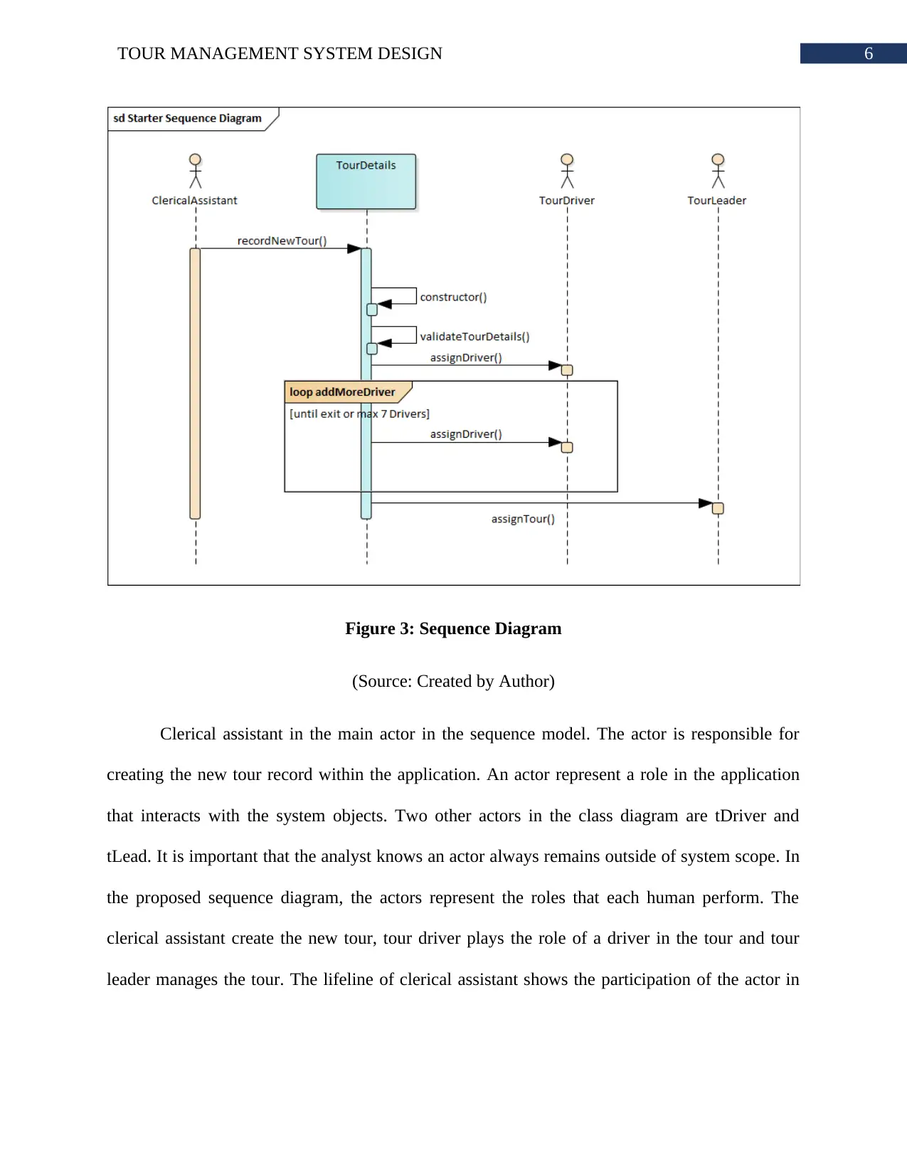
Figure 3: Sequence Diagram
(Source: Created by Author)
Clerical assistant in the main actor in the sequence model. The actor is responsible for
creating the new tour record within the application. An actor represent a role in the application
that interacts with the system objects. Two other actors in the class diagram are tDriver and
tLead. It is important that the analyst knows an actor always remains outside of system scope. In
the proposed sequence diagram, the actors represent the roles that each human perform. The
clerical assistant create the new tour, tour driver plays the role of a driver in the tour and tour
leader manages the tour. The lifeline of clerical assistant shows the participation of the actor in
Paraphrase This Document
Need a fresh take? Get an instant paraphrase of this document with our AI Paraphraser
7TOUR MANAGEMENT SYSTEM DESIGN
the sequence diagram. As illustrated in the sequence model of UML, the role of clerical assistant
does not end until the response form system regarding creation of new tour received.
Part 3
3.1 Evaluation:
Computer-Aided Software Engineering or CASE technologies are referred as the tools
which offers automated help in the task of software development. Primary aim of using CASE
tools are completing the software development process in less cost and time. The quality of the
end products is a primary focus in CASE tool utilization. The CASE tools helps designers to
achieve better results in software development in lesser time. The goals of using CASE tools is
based on improving product quality, increasing productivity, making software engineers' process
less revolting and facilitating maintenance (Udjaja 2018). Various organizations have not started
using CASE tools due to the fact that employees must be skilled enough to understand how the
case tools work. However, the organization that use CASE tools have admitted that it improved
documentation quality, evaluation of the system, showed ways of implementing efficient
maintenance and many more additional benefits.
CASE tools can have different functionalities based on the product. CASE tools are more
used in the early stages of the system development lifecycle. These stages are typically system
requirement gathering and analysis and system design. CASE tools also support the later stages
like code development. The support that CASE tools provided to the early SDLC stages is more
than later stages (Cardoso et al. 2018). Automated Diagram Support feature is a well-known
positive aspect of the CASE tool. The Automated Diagram Support feature provides a stack of
features that enables CASE tools to provide such good results to the project (Udjaja 2018). The

8TOUR MANAGEMENT SYSTEM DESIGN
CASE tools checks for the correctness of the syntax, provide support to data dictionary, checks
for completeness and consistency, navigation to the associated diagrams has been easy task,
layering of diagrams is possible in CASE tools, simulation between the systems has been better
and evaluation of the performance can be done in better way.
The System Design CASE tool was used for constructing the diagrams of World-Wide
Tours. Three of the diagrams are part of UML diagram. Each diagram represent different aspects
of the application. The class diagram shows static framework of the application (Feyisetan et al.
2017). On the other hand, the application sequence and communication diagrams shows the
behavioral patterns. Without the use of CASE tool, it was not possible to evaluate these three
diagrams properly. CASE tools provide the environment where diagrams could be created with
exact syntax and conventions (Cardoso et al. 2018). Each diagram properly designed and
structured. Aligning the designs of class, sequence and communication was very easy due to use
of CASE tool.
The analyst/designer can concentrate on improvement of entire system development
procedure in the era of continuously improving industry and small amount of success stories.
The analyst/designer can complete their work in less time and effort. The end result of
analyst/designer’s work will be of higher quality due to use of CASE tool (Frere, Royer and
Fourcade 2018). The productivity of analyst/designer will be improved while the work of
analyst/designer remains enjoyable. The analyst/designer can focus on their core work that is
defining the architecture of the application rather than worrying about coding. The
analyst/designer can develop prototypes for testing very easily because CASE tools provide
integrated environment which takes requirements as input and a working application as output.
Scope creep is a common issue in big and complex projects.
⊘ This is a preview!⊘
Do you want full access?
Subscribe today to unlock all pages.

Trusted by 1+ million students worldwide
9TOUR MANAGEMENT SYSTEM DESIGN
The CASE tools supports the analyst/designer by saving resources needed for software
development. The system design phase is completed and analyzed quickly by CASE tool. The
analyst/designer gets support of auto detecting errors that allows faster completion of work
(Udjaja 2018). The final designs made by analyst/designer are consisting of less errors. The
CASE tool also support the analyst/designer to generate quality designs.
Paraphrase This Document
Need a fresh take? Get an instant paraphrase of this document with our AI Paraphraser
10TOUR MANAGEMENT SYSTEM DESIGN
Bibliography:
Cardoso, J.G., Jensen, K., Lieven, C., Lærke Hansen, A.S., Galkina, S., Beber, M., Ozdemir, E.,
Herrgård, M.J., Redestig, H. and Sonnenschein, N., 2018. Cameo: a python library for computer
aided metabolic engineering and optimization of cell factories. ACS synthetic biology, 7(4),
pp.1163-1166.
Chren, S., Buhnova, B., Macak, M., Daubner, L. and Rossi, B., 2019, May. Mistakes in UML
diagrams: analysis of student projects in a software engineering course. In Proceedings of the
41st International Conference on Software Engineering: Software Engineering Education and
Training (pp. 100-109). IEEE Press.
Feyisetan, F.O., Abiodun, R.O., Fisayo, A., Olayinka, A.A. and Aremu, A.M., 2017. Computer
Aided Analysis of Pelton Turbine Runner. American Journal of Electrical and Computer
Engineering, 1(2), p.81.
Frere, L.M., Royer, M. and Fourcade, J., 2018. Tolerance Analysis Using a Computer Aided
Tolerancing Software: ANATOLE 3D. Procedia CIRP, 75, pp.267-272.
Ibrahim, R., Aman, H., Nayak, R. and Jamel, S., 2018. Consistency Check between XML
Schema and Class Diagram for Document Versioning. International Journal on Advanced
Science, Engineering and Information Technology, 8(6), pp.2590-2597.
Karim, S., Liawatimena, S., Trisetyarso, A., Abbas, B.S. and Suparta, W., 2017, November.
Automating functional and structural software size measurement based on XML structure of
UML sequence diagram. In 2017 IEEE International Conference on Cybernetics and
Computational Intelligence (CyberneticsCom) (pp. 24-28). IEEE.

11TOUR MANAGEMENT SYSTEM DESIGN
Khurana, N., Chhillar, R.S. and Chhillar, U., 2016. A Novel Technique for Generation and
Optimization of Test Cases Using Use Case, Sequence, Activity Diagram and Genetic
Algorithm. JSW, 11(3), pp.242-250.
Sulaiman, N., Ahmad, S.S.S. and Ahmad, S., 2019. Logical approach: Consistency rules between
activity diagram and class diagram. International Journal on Advanced Science, Engineering and
Information Technology, 9(2), p.552.
Udjaja, Y., 2018. Ekspanpixel Bladsy Stranica: Performance Efficiency Improvement of Making
Front-End Website Using Computer Aided Software Engineering Tool. Procedia Computer
Science, 135, pp.292-301.
⊘ This is a preview!⊘
Do you want full access?
Subscribe today to unlock all pages.

Trusted by 1+ million students worldwide
1 out of 12
Related Documents
Your All-in-One AI-Powered Toolkit for Academic Success.
+13062052269
info@desklib.com
Available 24*7 on WhatsApp / Email
![[object Object]](/_next/static/media/star-bottom.7253800d.svg)
Unlock your academic potential
Copyright © 2020–2025 A2Z Services. All Rights Reserved. Developed and managed by ZUCOL.


