Tower Bridge: An Engineering Design and Systems Case Study
VerifiedAdded on 2023/06/04
|12
|2846
|51
Case Study
AI Summary
This case study delves into the design and engineering of the Tower Bridge, a combined suspension and bascule bridge in London. It examines the preliminary design phase, including system and functional analyses, design criteria allocation, and subsystem analyses. The detailed design section covers system and product design, focusing on the hydraulic system and control signaling. The study further evaluates system prototype testing, traffic management, and river navigation considerations. It also addresses the utilization and support aspects, along with system testing, validation, and optimization processes. The analysis incorporates the bridge's structural maintenance, load management (dead, live, and dynamic loads), and the evolution of its operating mechanisms from steam-powered hydraulics to electro-hydraulic drives. The document explores the control systems used for river traffic management, including semaphore signals and lighting systems, and highlights the bridge's ongoing maintenance and adaptation to modern traffic needs. Desklib provides access to this and other solved assignments for students.
Design of Tower Bridge 1
DESIGN OF TOWER BRIDGE
A Research Paper on Bridge By
Student’s Name
Name of the Professor
Institutional Affiliation
City/State
Year/Month/Day
DESIGN OF TOWER BRIDGE
A Research Paper on Bridge By
Student’s Name
Name of the Professor
Institutional Affiliation
City/State
Year/Month/Day
Paraphrase This Document
Need a fresh take? Get an instant paraphrase of this document with our AI Paraphraser
Design of Tower Bridge 2
Table of Contents
INTRODUCTION...........................................................................................................................................3
PRELIMINARY DESIGN..................................................................................................................................3
System and functional analyses...............................................................................................................3
Synthesis and allocation of the design criteria........................................................................................4
System and subsystem analyses..............................................................................................................5
Detailed design............................................................................................................................................5
System and product design.....................................................................................................................5
Hydraulic system.................................................................................................................................6
Control and signaling...........................................................................................................................6
System prototype test and evaluation.....................................................................................................7
Traffics.................................................................................................................................................7
River....................................................................................................................................................7
Utilization and support............................................................................................................................7
System test, validation and optimization process.......................................................................................8
Evaluation....................................................................................................................................................9
Conclusion...................................................................................................................................................9
Bibliography...............................................................................................................................................11
Design of Tower Bridge 3
INTRODUCTION
Tower Bridge is a combined suspension and Bascule Bridge in London constructed from 1886 to
1894. The bridge has the become the iconic symbol of the London and it crosses the Thames
river close to the London tower. The bridge comprises of two bridge towers tied together by two
horizontal walkways tied together at the upper level constructed to withstand the horizontal
forces caused by the suspended section of the bridge on the tower’s landward side. The vertical
components of the forces in the section suspended and the vertical reaction in a two walkway are
carried by two towers. The bascule pivots and operating machines are housed in the base of
every tower. The deck of the bridge is accessible to both vehicles and pedestrians. This research
paper was about the hydraulic bridge and the selected named one is the tower bridge which falls
under suspension and Bascule Bridge. It is based on the machines that lift the part of the bridge
so that it can allow the river traffic under it to pass. The bridge is near the harbor so it was
important for it to be designed in the type that can enable the ships to pass. The machines that
were replaced by the electro hydraulic drive were left in the museum of the tower bridge to
attract the tourists.
PRELIMINARY DESIGN
System and functional analyses
A great problem faced the London city which was how to construct a bridge downstream from
the London Bridge without affecting the activities of the river traffic. The produce the ideas, the
subway committee was organized and opened the designs for the new crossing to the competition
publicly. More design were forwarded fir the consideration and then the contractors chose design
for the tower bridge as the solution (Billington, 2015).
It is open to the public and forms the basis for the museum of the bridge, which resides in old
rooms of the engine on the bridge’s south side. The museums comprises the steam engines, 2
⊘ This is a preview!⊘
Do you want full access?
Subscribe today to unlock all pages.

Trusted by 1+ million students worldwide
Design of Tower Bridge 4
accumulators, and one of the engines of hydraulic that moved to the bascules along the related
artefacts. The exhibitions are normally carried out on the bridge walkways, it uses the photos,
films, and the interactive displays to explain how the tower bridge was constructed, the bridge
was also used for the recreation and also it helped the people to pass form one side to another
(Blockley, 2012).
Synthesis and allocation of the design criteria
The construction of the tower bridge started in 1886 and took around 8 years with the five main
contractors. Two massive piers with more than seventy thousand tons of the concrete were sunk
into the riverbed to support the building. More than eleven thousand tons of steel gave the
framework for the walkways and the towers. This was later clad in the granite and stones of
Portland to protect the fundamental steel work and provide the bridge with an attractive look. In
1974, the operating mechanism was replaced by the hydraulic system, designed with original
pinions driven by the modern hydraulic gearings and motors. A computer system was installed to
control the lowering and raising if the bascules slightly. It proved unreliable, causing the bridge
to be stuck in closed or open positions on many events until the sensors were replaced. Facelift o
the bridge occurred in 2008 where the work comprise the stripping off the available paints and
repaint in white and blue. Every section was covered in scaffold and sheets of plastics to ensure
that the old paints don’t fall in the Thames River to cause pollution (Brangwyn, 2014). The
walkways were constructed and renovated and within the walkways, a lighting system was
installed to help when the walkways are used for the exhibitions and functions. The system
helped in providing the atmospheric lighting, and was designed to be hidden within the
superstructure of the bridge and fixed without the drilling (Council, 2016).
Paraphrase This Document
Need a fresh take? Get an instant paraphrase of this document with our AI Paraphraser
Design of Tower Bridge 5
System and subsystem analyses
The tower bridge was closed to all the roads for about 3 months, to allow the structural work of
maintenance to occur. The work were; doing main maintenance to the systems that lifts the
bridge. Substituting the decking and rematerializing the roads and walkway, substituting the
joints for expansion along the bridge to give a smooth surface and structure, waterproofing the
arches designed from the bricks on the slants to the bridge (Duan, 2017).
Detailed design
System and product design
The tower bridge is eight hundred feet long with the two towers every two hundred and thirteen
height, designed on the piers. The span at the center of two hundred feet between the towers is
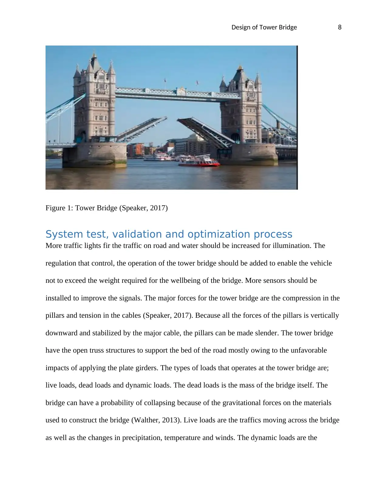
divided into two similar leaves or bascules which can be raised to 87 degrees to allow the traffic
in river to pass. The bascules with the mass of more than one thousand tones are counterbalanced
to reduce the force needed and enable the raising within five minutes. The two side spans are the
suspension bridges every two hundred and fifty length with the suspension rods anchored at the
abutments and through the rods confined within the upper walkway of the bridge. The pedestrian
walkway are the one hundred and forty three feet above the river at the high tides (Edward,
2013).
The major deck of the bridge carries two lanes of the traffic roads between low level walkway of
the pedestrian across the spans of suspension and the opening the section of bascule of the
bridge, with the walkway divided from the roads by the fences. The roads passes through the two
towers whereas the walkway of low level passes around the outside the towers. One of the
bridge’s chimneys normally thought to be the posts lamps connects to the old place of fire in the
guardroom of the tower (Frangopol, 2016).
Design of Tower Bridge 6
Hydraulic system
The raising mechanism was given the power by the stored water in numerous accumulators of
hydraulics. The system was constructed and fitted then water at a high pressure was pumped into
the accumulators by the stationary engines of steams installed with the Mayer slide expansion
valves. Every engine made a force pump from its tail piston rod. Every accumulators consists of
20 inch where sits a heavy, as to maintain the pressure desired. The whole hydraulic mechanisms
and the gas systems for lighting was fitted. Initially the gas lighting was by the open burners of
the flames within the lantern but were improved to the incandescent system. The original
machines for operation were replaced by the electro hydraulic drive system. The constituents of
the original system still applied are the final pinions that engage to the racks installed to the
bascules. They are controlled by the hydraulic gearings and motors using the as the hydraulic
fluid instead of water. Some of the hydraulic machinery has been retained, even though it is not
used nowadays (Frangopol, 2016).
Control and signaling
To control the passage of the traffic river through the bridge, many dissimilar rules and the
signals were used. The control at daytime was given by the signals of the red semaphore, placed
on the small control cabins on end of the piers of the bridge. At night hours, the lights that are
colored were used in both directions and on every piers, 2 red lights to display that the bridge
was closed and 2 green to show that the bridge was open and a gong was sounded in the foggy
weather (Langmead, 2014).
The vessels that passes through the bridge had to show the signals: at daytime, the black ball
which is two feet in diameter was placed high up when it could be seen by everuyone.at night, 2
red lights were mounted in the same position. The foggy weather require the repetitive blasts
⊘ This is a preview!⊘
Do you want full access?
Subscribe today to unlock all pages.

Trusted by 1+ million students worldwide
Design of Tower Bridge 7
from the whistle steam of the ship. If the black ball is suspended from the center of every
walkway this show that the bridge count not be opened (MacDonald, 2014).
System prototype test and evaluation
Traffics
The tower bridge is very busy crossed by more than forty thousand people daily. To maintain the
structure’s integrity, the corporation of the London city has imposed 32km/pour restriction of the
speed, and a limit of eighteen tons mass on the vehicles that use the bridge. The system of
camera is used to measure the traffic speed crossing the bridge using the recognition system of
the number plate to send the penalty that is fixed to the speeding drivers. Another system
monitors the parameter of the vehicles, the piezoelectric sensors and the induction loops are used
to measure the mass and the axle’s number in every car (MacDonald, 2013).
River; the bascules are raised around one thousand times yearly. The traffic in the river is
decreased but still takes the priority over the traffic of the road. The notices are needed before the
bridge is opened and the times for opening are published in the website of the bridge in advance.
When requiring to be raised for the vessel passage, the bascules are raised to the sufficient angle
for the vessel to pass under the bridge safely (Macaula, 2015).
Utilization and support
When it was built the tower bridge was the longest and largest and most sophisticates’ type of
the bascule bridge ever completed. These bascules were controlled by the hydraulic machines
that uses the steam to produce the power for pumping the engine. The energy generated was
stored in the 6 huge accumulators, when the power was needed to lift the bridge it was normally
available. The accumulators fed the engines for driving which control the bascules down and up.
Despite the fact that the system was complex the bascules took a minute to raise to their highest
angle of 86degrees (POWEL, 2017).
Paraphrase This Document
Need a fresh take? Get an instant paraphrase of this document with our AI Paraphraser
Design of Tower Bridge 8
Figure 1: Tower Bridge (Speaker, 2017)
System test, validation and optimization process
More traffic lights fir the traffic on road and water should be increased for illumination. The
regulation that control, the operation of the tower bridge should be added to enable the vehicle
not to exceed the weight required for the wellbeing of the bridge. More sensors should be
installed to improve the signals. The major forces for the tower bridge are the compression in the
pillars and tension in the cables (Speaker, 2017). Because all the forces of the pillars is vertically
downward and stabilized by the major cable, the pillars can be made slender. The tower bridge
have the open truss structures to support the bed of the road mostly owing to the unfavorable
impacts of applying the plate girders. The types of loads that operates at the tower bridge are;
live loads, dead loads and dynamic loads. The dead loads is the mass of the bridge itself. The
bridge can have a probability of collapsing because of the gravitational forces on the materials
used to construct the bridge (Walther, 2013). Live loads are the traffics moving across the bridge
as well as the changes in precipitation, temperature and winds. The dynamic loads are the
Design of Tower Bridge 9
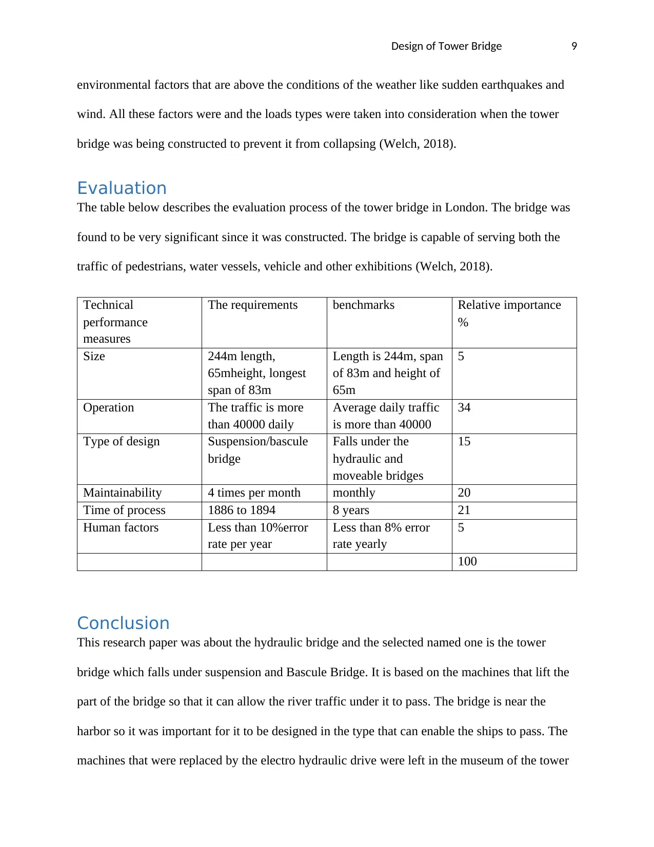
environmental factors that are above the conditions of the weather like sudden earthquakes and
wind. All these factors were and the loads types were taken into consideration when the tower
bridge was being constructed to prevent it from collapsing (Welch, 2018).
Evaluation
The table below describes the evaluation process of the tower bridge in London. The bridge was
found to be very significant since it was constructed. The bridge is capable of serving both the
traffic of pedestrians, water vessels, vehicle and other exhibitions (Welch, 2018).
Technical
performance
measures
The requirements benchmarks Relative importance
%
Size 244m length,
65mheight, longest
span of 83m
Length is 244m, span
of 83m and height of
65m
5
Operation The traffic is more
than 40000 daily
Average daily traffic
is more than 40000
34
Type of design Suspension/bascule
bridge
Falls under the
hydraulic and
moveable bridges
15
Maintainability 4 times per month monthly 20
Time of process 1886 to 1894 8 years 21
Human factors Less than 10%error
rate per year
Less than 8% error
rate yearly
5
100
Conclusion
This research paper was about the hydraulic bridge and the selected named one is the tower
bridge which falls under suspension and Bascule Bridge. It is based on the machines that lift the
part of the bridge so that it can allow the river traffic under it to pass. The bridge is near the
harbor so it was important for it to be designed in the type that can enable the ships to pass. The
machines that were replaced by the electro hydraulic drive were left in the museum of the tower
⊘ This is a preview!⊘
Do you want full access?
Subscribe today to unlock all pages.

Trusted by 1+ million students worldwide
Design of Tower Bridge 10
bridge to attract the tourists. The bridge comprises of two bridge towers tied together by two
horizontal walkways tied together at the upper level constructed to withstand the horizontal
forces caused by the suspended section of the bridge on the tower’s landward side. The vertical
components of the forces in the section suspended and the vertical reaction in a two walkway are
carried by two towers. The bascule pivots and operating machines are housed in the base of
every tower. The deck of the bridge is accessible to both vehicles and pedestrians.
Paraphrase This Document
Need a fresh take? Get an instant paraphrase of this document with our AI Paraphraser
Design of Tower Bridge 11
Bibliography
Billington, D., 2015. The Tower and the Bridge. Michigan: Princeton University Press.
Blockley, D., 2012. Bridges. Paris: OUP Oxford.
Brangwyn, F., 2014. A Book of Bridges. Toledo: Read Books.
Bridge, T., 2016. Tower Bridge. Melbourne: Scala Arts & Heritage Publishers Limited.
Council, N. R., 2016. Bridge Aesthetics Around the World. Paris: Transportation Research Board.
Duan, L., 2017. Bridge Engineering Handbook. Colorado: CRC Press.
Edward, J., 2013. The Tower Bridge. Michigan: Office of "The Engineer.
Frangopol, D., 2016. Bridge Maintenance, Safety, Management and Life-Cycle Optimization. Perh: CRC
Press.
Langmead, D., 2014. Encyclopedia of Architectural and Engineering Feats. Michigan: ABC-CLIO.
Macaula, D., 2015. Building Big. Paris: Houghton Mifflin Harcourt.
MacDonald, D., 2013. Golden Gate Bridge. New York: Chronicle Books.
MacDonald, D., 2014. Bay Bridge. Colorado: Chronicle Books.
POWEL, K., 2017. Tower Bridge. Chicago: Thames & Hudson Limited.
Speaker, M., 2017. The London Tower Bridge. Melbourne: Blackbirch Press.
Walther, R., 2013. Cable Stayed Bridges. Toledo: Thomas Telford.
Welch, C., 2018. History of the Tower Bridge and of Other Bridges Over the Thames Built by the
Corporation of London. Michigan: Smith, Elder and Company.

Design of Tower Bridge 12
⊘ This is a preview!⊘
Do you want full access?
Subscribe today to unlock all pages.

Trusted by 1+ million students worldwide
1 out of 12
Your All-in-One AI-Powered Toolkit for Academic Success.
+13062052269
info@desklib.com
Available 24*7 on WhatsApp / Email
![[object Object]](/_next/static/media/star-bottom.7253800d.svg)
Unlock your academic potential
© 2024 | Zucol Services PVT LTD | All rights reserved.
