Traffic Light Control System
VerifiedAdded on 2023/04/17
|8
|750
|406
AI Summary
This report discusses the design and implementation of a two-way traffic light control system using a Moore finite state system. The system includes traffic lights in the north-south and east-west directions, with signals for red, green, and yellow. The signals change based on a synchronous digital clock and a safe signal. The report also includes state representation, Boolean logic functions, and a circuit diagram.
Contribute Materials
Your contribution can guide someone’s learning journey. Share your
documents today.
Running head: TRAFFIC LIGHT CONTROL SYSTEM
TRAFFIC LIGHT CONTROL SYSTEM
Name of the Student
Name of the University
Author Note
TRAFFIC LIGHT CONTROL SYSTEM
Name of the Student
Name of the University
Author Note
Secure Best Marks with AI Grader
Need help grading? Try our AI Grader for instant feedback on your assignments.
2TRAFFIC LIGHT CONTROL SYSTEM
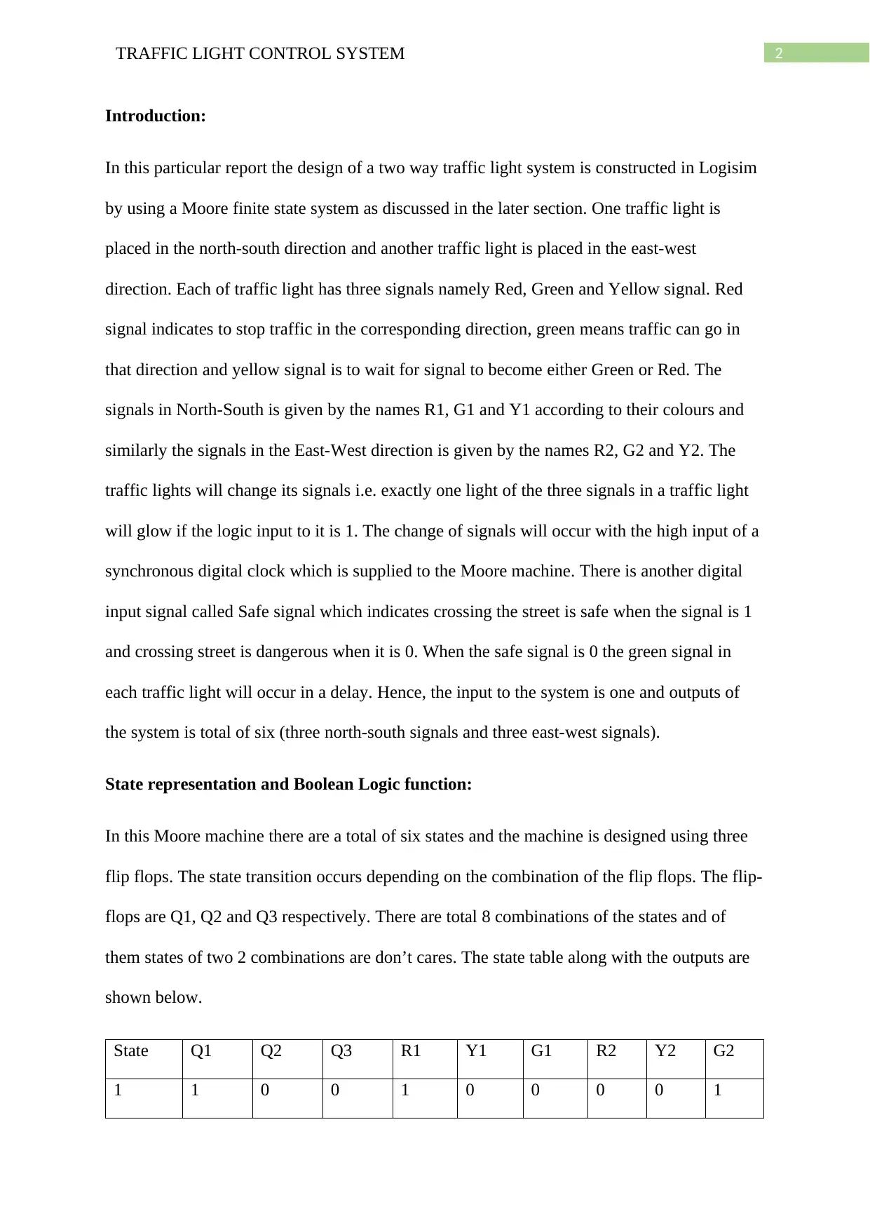
Introduction:
In this particular report the design of a two way traffic light system is constructed in Logisim
by using a Moore finite state system as discussed in the later section. One traffic light is
placed in the north-south direction and another traffic light is placed in the east-west
direction. Each of traffic light has three signals namely Red, Green and Yellow signal. Red
signal indicates to stop traffic in the corresponding direction, green means traffic can go in
that direction and yellow signal is to wait for signal to become either Green or Red. The
signals in North-South is given by the names R1, G1 and Y1 according to their colours and
similarly the signals in the East-West direction is given by the names R2, G2 and Y2. The
traffic lights will change its signals i.e. exactly one light of the three signals in a traffic light
will glow if the logic input to it is 1. The change of signals will occur with the high input of a
synchronous digital clock which is supplied to the Moore machine. There is another digital
input signal called Safe signal which indicates crossing the street is safe when the signal is 1
and crossing street is dangerous when it is 0. When the safe signal is 0 the green signal in
each traffic light will occur in a delay. Hence, the input to the system is one and outputs of
the system is total of six (three north-south signals and three east-west signals).
State representation and Boolean Logic function:
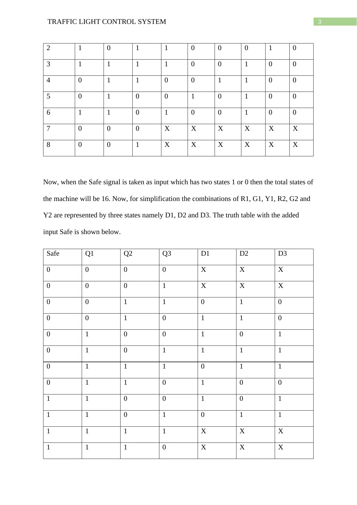
In this Moore machine there are a total of six states and the machine is designed using three
flip flops. The state transition occurs depending on the combination of the flip flops. The flip-
flops are Q1, Q2 and Q3 respectively. There are total 8 combinations of the states and of
them states of two 2 combinations are don’t cares. The state table along with the outputs are
shown below.
State Q1 Q2 Q3 R1 Y1 G1 R2 Y2 G2
1 1 0 0 1 0 0 0 0 1
3TRAFFIC LIGHT CONTROL SYSTEM
2 1 0 1 1 0 0 0 1 0
3 1 1 1 1 0 0 1 0 0
4 0 1 1 0 0 1 1 0 0
5 0 1 0 0 1 0 1 0 0
6 1 1 0 1 0 0 1 0 0
7 0 0 0 X X X X X X
8 0 0 1 X X X X X X
Now, when the Safe signal is taken as input which has two states 1 or 0 then the total states of
the machine will be 16. Now, for simplification the combinations of R1, G1, Y1, R2, G2 and
Y2 are represented by three states namely D1, D2 and D3. The truth table with the added
input Safe is shown below.
Safe Q1 Q2 Q3 D1 D2 D3
0 0 0 0 X X X
0 0 0 1 X X X
0 0 1 1 0 1 0
0 0 1 0 1 1 0
0 1 0 0 1 0 1
0 1 0 1 1 1 1
0 1 1 1 0 1 1
0 1 1 0 1 0 0
1 1 0 0 1 0 1
1 1 0 1 0 1 1
1 1 1 1 X X X
1 1 1 0 X X X
4TRAFFIC LIGHT CONTROL SYSTEM
1 0 0 0 X X X
1 0 0 1 X X X
1 0 1 1 0 1 0
1 0 1 0 1 0 0
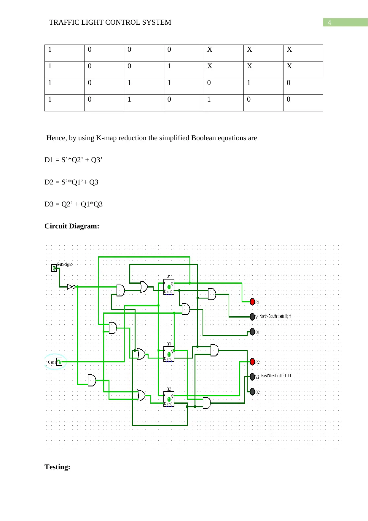
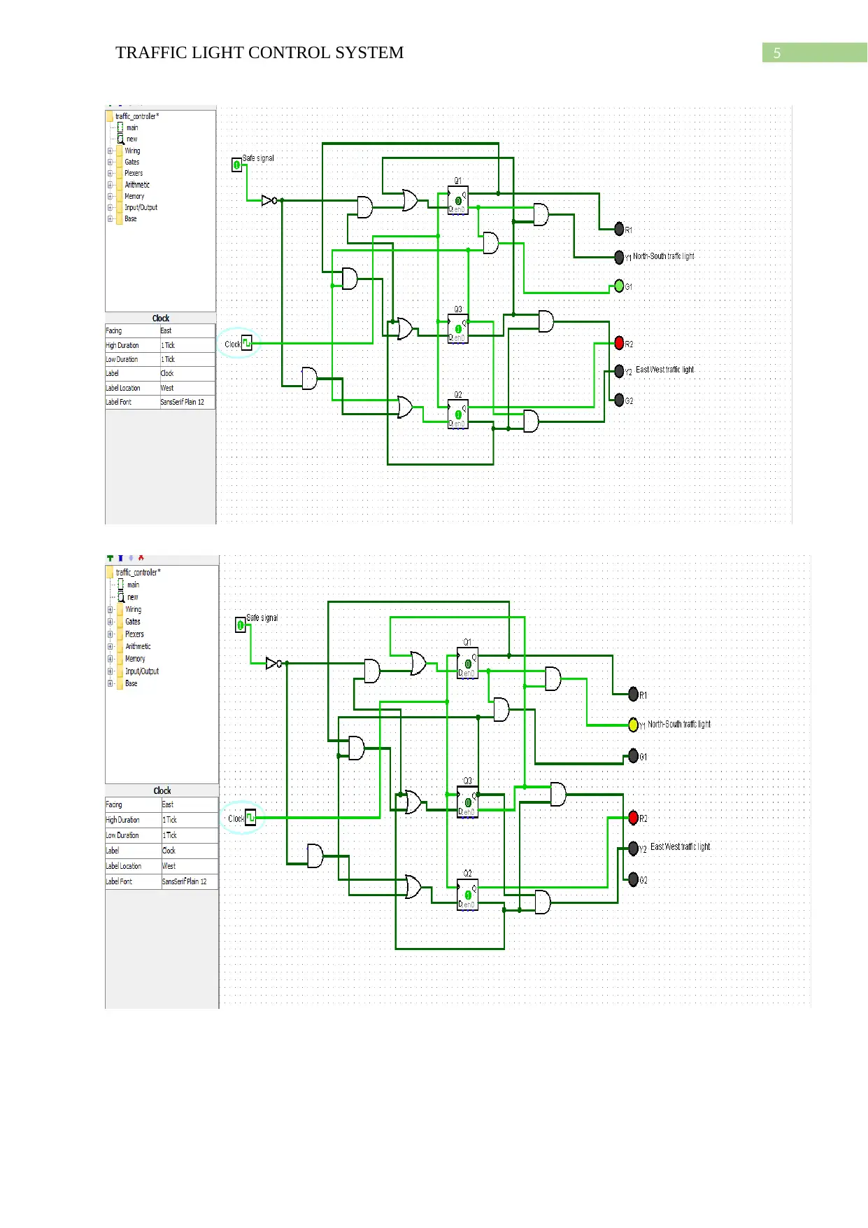
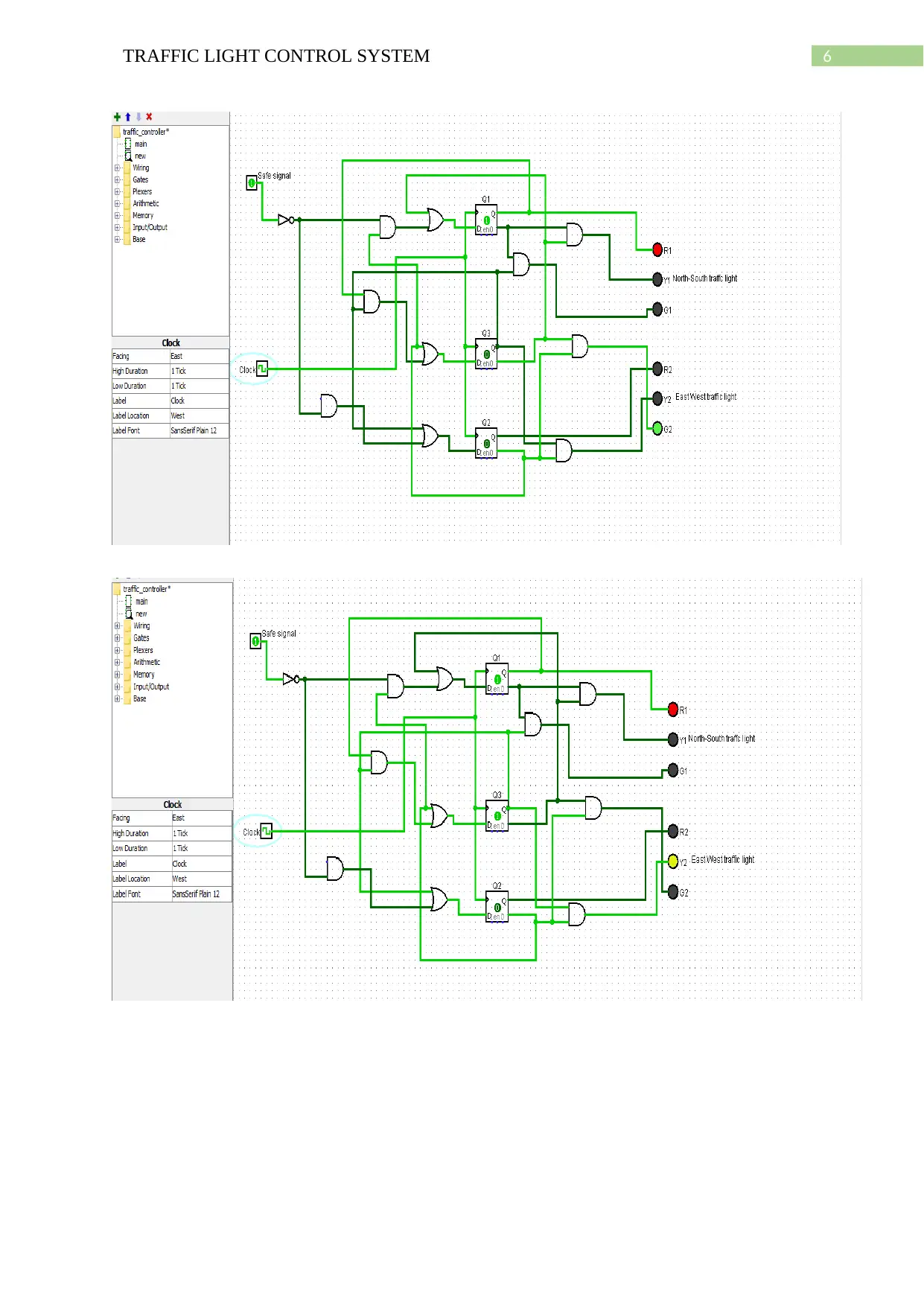
Hence, by using K-map reduction the simplified Boolean equations are
D1 = S’*Q2’ + Q3’
D2 = S’*Q1’+ Q3
D3 = Q2’ + Q1*Q3
Circuit Diagram:
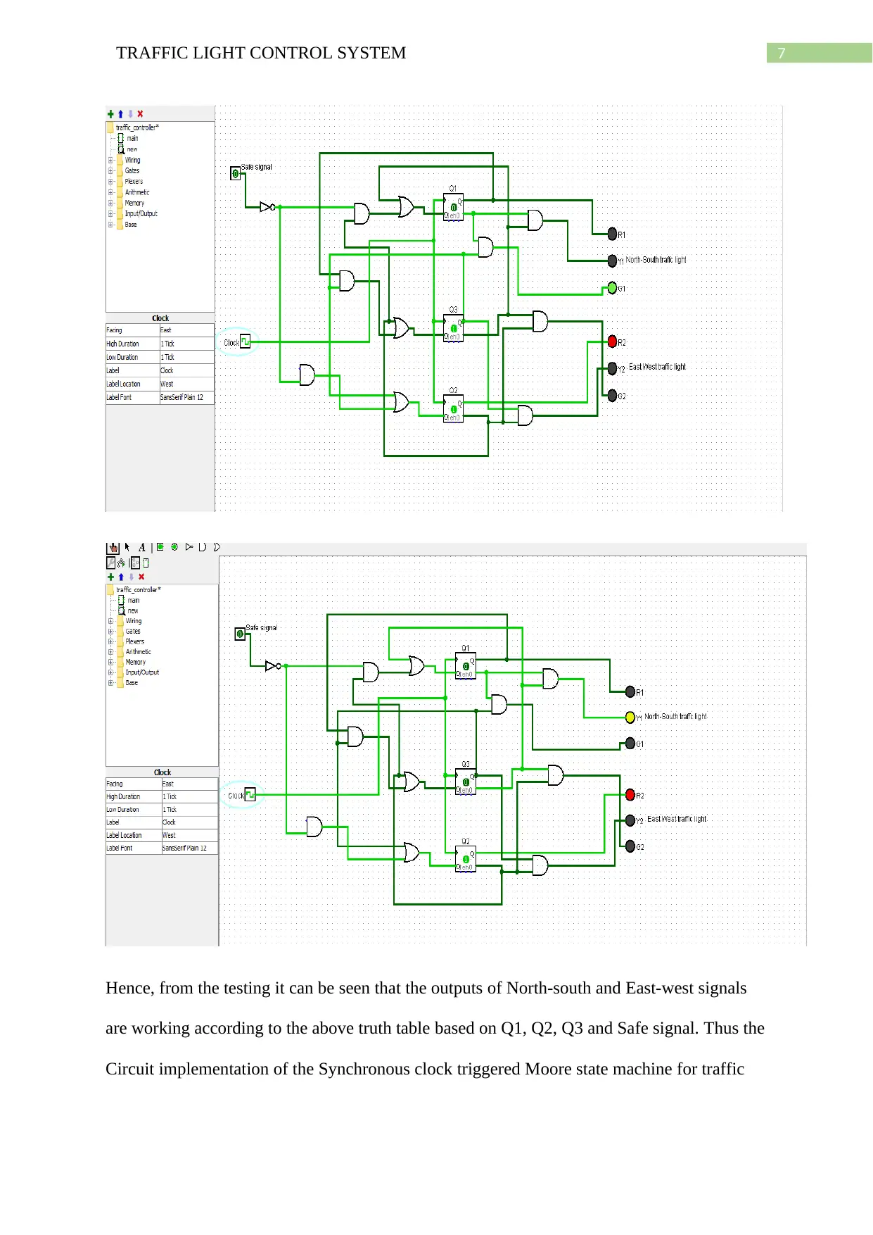
Testing:
1 0 0 0 X X X
1 0 0 1 X X X
1 0 1 1 0 1 0
1 0 1 0 1 0 0
Hence, by using K-map reduction the simplified Boolean equations are
D1 = S’*Q2’ + Q3’
D2 = S’*Q1’+ Q3
D3 = Q2’ + Q1*Q3
Circuit Diagram:
Testing:
Secure Best Marks with AI Grader
Need help grading? Try our AI Grader for instant feedback on your assignments.
5TRAFFIC LIGHT CONTROL SYSTEM
6TRAFFIC LIGHT CONTROL SYSTEM
7TRAFFIC LIGHT CONTROL SYSTEM
Hence, from the testing it can be seen that the outputs of North-south and East-west signals
are working according to the above truth table based on Q1, Q2, Q3 and Safe signal. Thus the
Circuit implementation of the Synchronous clock triggered Moore state machine for traffic
Hence, from the testing it can be seen that the outputs of North-south and East-west signals
are working according to the above truth table based on Q1, Q2, Q3 and Safe signal. Thus the
Circuit implementation of the Synchronous clock triggered Moore state machine for traffic
Paraphrase This Document
Need a fresh take? Get an instant paraphrase of this document with our AI Paraphraser
8TRAFFIC LIGHT CONTROL SYSTEM
light control is appropriate and the circuit is very simple as the K-map techniques of reduced
Boolean logic function is used to make the final circuit.
light control is appropriate and the circuit is very simple as the K-map techniques of reduced
Boolean logic function is used to make the final circuit.
1 out of 8
Your All-in-One AI-Powered Toolkit for Academic Success.
+13062052269
info@desklib.com
Available 24*7 on WhatsApp / Email
![[object Object]](/_next/static/media/star-bottom.7253800d.svg)
Unlock your academic potential
© 2024 | Zucol Services PVT LTD | All rights reserved.