Comprehensive Review: Transducers for Biomedical Applications
VerifiedAdded on 2021/06/07
|3
|1613
|112
Report
AI Summary
This report provides a comprehensive overview of transducers used in various biomedical applications. It begins by defining transducers and their role in converting physical and chemical quantities into electrical signals for physiological measurements and patient monitoring. The report then delves into specific transducer types, including those used for blood pressure measurement (strain gauges, LVDTs, and capacitive sensors), blood flow measurement (electromagnetic flow meters), and temperature measurement (thermistors and thermocouples). Furthermore, the report discusses ultrasonic transducers and their application in medical imaging. Each section explains the working principles, advantages, and disadvantages of each transducer type, along with relevant diagrams and figures. The report concludes by summarizing the diverse applications of transducers in biomedical engineering and their importance in modern healthcare.

Transducers For Biomedical Applications
Abstract – A transducer is a device that converts a measured
object quantity into an electrical signal. Biomedical transducers
are transducers with specific uses in biomedical applications,
such as physiological measurement, patient monitoring, and in
health care. The object quantities in biomedical measurements
are physical and chemical quantities that reflect the physiological
functions in a living body. Although some quantities, such as
blood composition, can be determined from a sample extracted
from the body, real-time and continuous measurements can be
achieved if a transducer is attached to the body, and use of a
transducer attached to the body is essential when continuous
monitoring of an object quantity is required. Transducers used in
various biomedical applications are explained in this paper.
Index terms - Transducer, physiological, biomedical
measurements, patient monitoring.
INTRODUCTION
A transducer is a device that converts one form of energy to
another form of energy. Energy types include electrical,
mechanical, electromagnetic (including light), chemical,
acoustic, and thermal energy. Usually a transducer converts a
signal in one form of energy to a signal in another, but any
variable attenuation of energy may serve as input. A sensor is
used to detect a parameter in one form and report it in another
form of energy, often an electrical signal. For example, a
pressure sensor might detect pressure (a mechanical form of
energy) and convert it to electrical signal for display at a
remote gauge. Transducers are selected based on several
factors such as sensitivity, operating range, accuracy, cross
sensitivity, errors, operating principle etc.
I. TRANSDUCERS FOR BIOMEDICAL APPLICATIONS
Different types of transducers are extensively used in
biomedical applications.
a. Transducers for Blood Pressure Measurement
Blood pressure measurement is used to diagnose malfunction
of the heart or cardiovascular system.The sphygmomanometer
is the most common method of blood pressure measurement,
whereby an in-flatable cuff is used to measure both systolic
and diastolic blood pressures. However, when more accurate
blood measurements are required, involving spatial and
temporal profiles within the blood circulation, then internal
blood pressure measurements need to be made[1]. Different
types of pressure transducers have been used for direct
measurements of blood pressure, incorporating a strain gauge,
linear-variable differential transformer, variable inductance or
capacitive device, optoelectronic materials, piezoelectric
materials, etc.
1. Strain Gauges
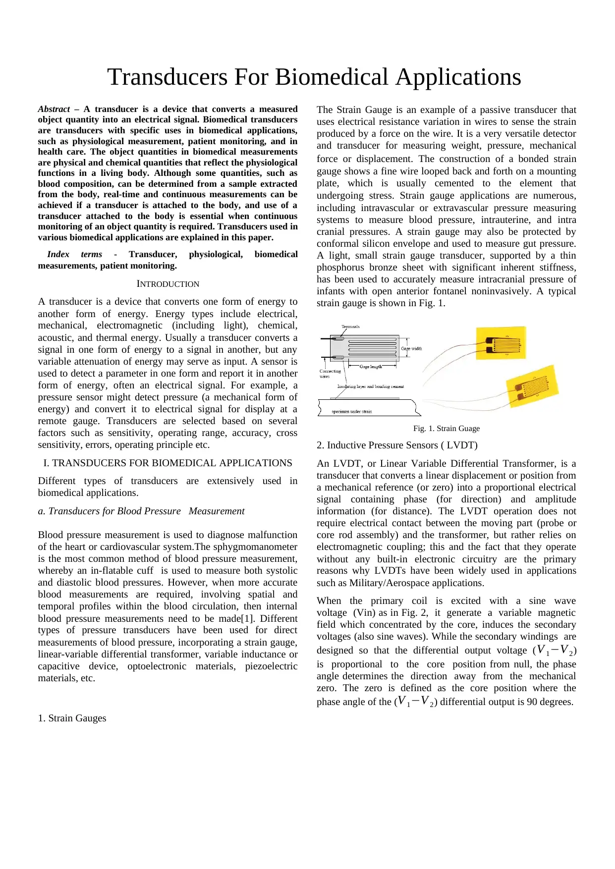
The Strain Gauge is an example of a passive transducer that
uses electrical resistance variation in wires to sense the strain
produced by a force on the wire. It is a very versatile detector
and transducer for measuring weight, pressure, mechanical
force or displacement. The construction of a bonded strain
gauge shows a fine wire looped back and forth on a mounting
plate, which is usually cemented to the element that
undergoing stress. Strain gauge applications are numerous,
including intravascular or extravascular pressure measuring
systems to measure blood pressure, intrauterine, and intra
cranial pressures. A strain gauge may also be protected by
conformal silicon envelope and used to measure gut pressure.
A light, small strain gauge transducer, supported by a thin
phosphorus bronze sheet with significant inherent stiffness,
has been used to accurately measure intracranial pressure of
infants with open anterior fontanel noninvasively. A typical
strain gauge is shown in Fig. 1.
Fig. 1. Strain Guage
2. Inductive Pressure Sensors ( LVDT)
An LVDT, or Linear Variable Differential Transformer, is a
transducer that converts a linear displacement or position from
a mechanical reference (or zero) into a proportional electrical
signal containing phase (for direction) and amplitude
information (for distance). The LVDT operation does not
require electrical contact between the moving part (probe or
core rod assembly) and the transformer, but rather relies on
electromagnetic coupling; this and the fact that they operate
without any built-in electronic circuitry are the primary
reasons why LVDTs have been widely used in applications
such as Military/Aerospace applications.
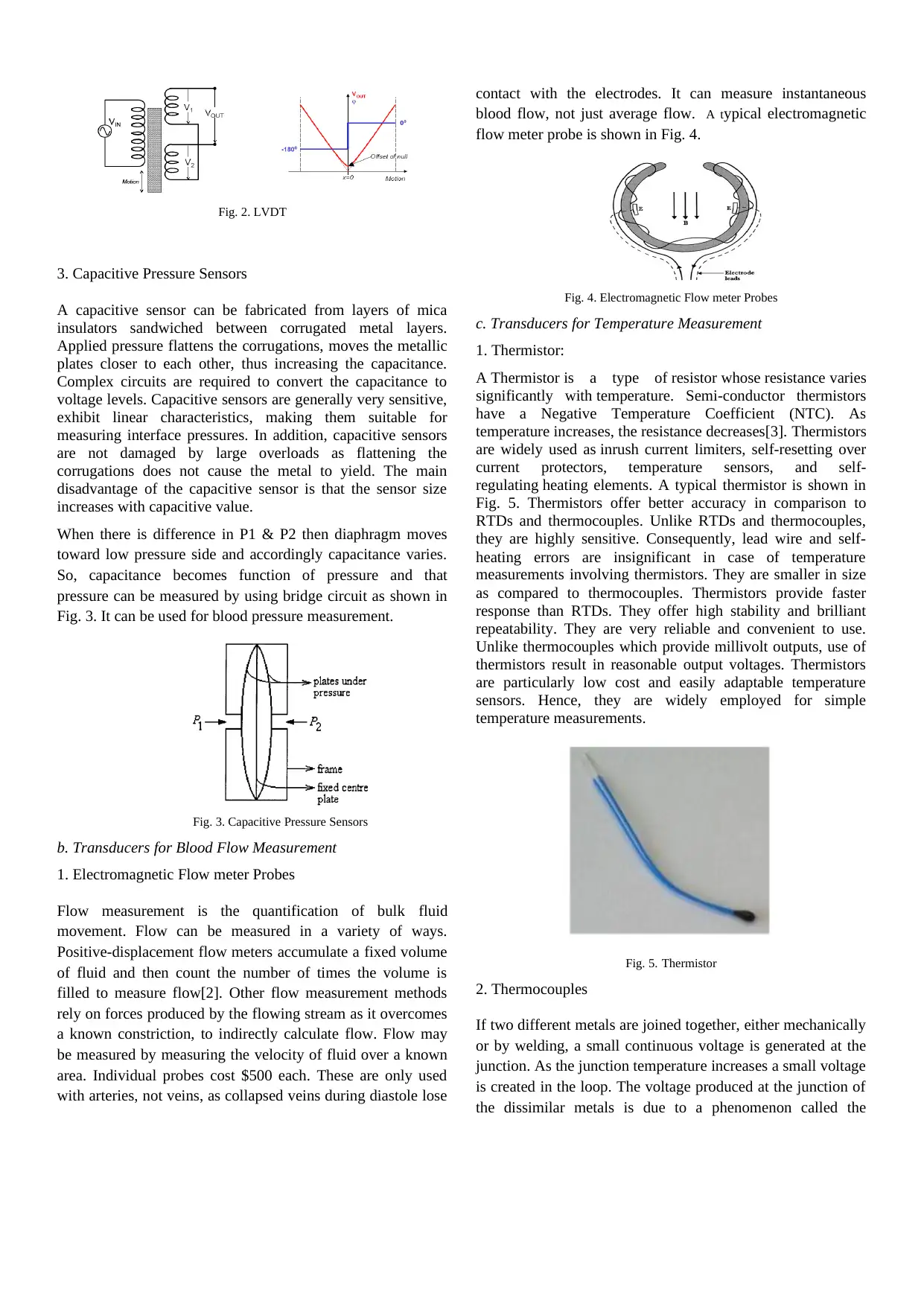
When the primary coil is excited with a sine wave
voltage (Vin) as in Fig. 2, it generate a variable magnetic
field which concentrated by the core, induces the secondary
voltages (also sine waves). While the secondary windings are
designed so that the differential output voltage ( V 1−V 2)
is proportional to the core position from null, the phase
angle determines the direction away from the mechanical
zero. The zero is defined as the core position where the
phase angle of the (V 1−V 2) differential output is 90 degrees.
Paraphrase This Document
Need a fresh take? Get an instant paraphrase of this document with our AI Paraphraser

Fig. 2. LVDT
3. Capacitive Pressure Sensors
A capacitive sensor can be fabricated from layers of mica
insulators sandwiched between corrugated metal layers.
Applied pressure flattens the corrugations, moves the metallic
plates closer to each other, thus increasing the capacitance.
Complex circuits are required to convert the capacitance to
voltage levels. Capacitive sensors are generally very sensitive,
exhibit linear characteristics, making them suitable for
measuring interface pressures. In addition, capacitive sensors
are not damaged by large overloads as flattening the
corrugations does not cause the metal to yield. The main
disadvantage of the capacitive sensor is that the sensor size
increases with capacitive value.
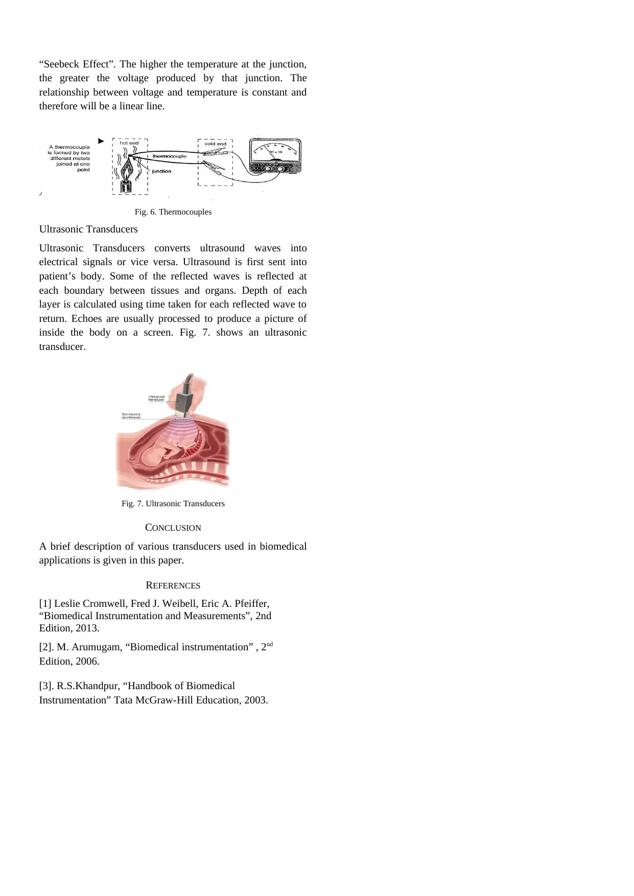
When there is difference in P1 & P2 then diaphragm moves
toward low pressure side and accordingly capacitance varies.
So, capacitance becomes function of pressure and that
pressure can be measured by using bridge circuit as shown in
Fig. 3. It can be used for blood pressure measurement.
Fig. 3. Capacitive Pressure Sensors
b. Transducers for Blood Flow Measurement
1. Electromagnetic Flow meter Probes
Flow measurement is the quantification of bulk fluid
movement. Flow can be measured in a variety of ways.
Positive-displacement flow meters accumulate a fixed volume
of fluid and then count the number of times the volume is
filled to measure flow[2]. Other flow measurement methods
rely on forces produced by the flowing stream as it overcomes
a known constriction, to indirectly calculate flow. Flow may
be measured by measuring the velocity of fluid over a known
area. Individual probes cost $500 each. These are only used
with arteries, not veins, as collapsed veins during diastole lose
contact with the electrodes. It can measure instantaneous
blood flow, not just average flow. A typical electromagnetic
flow meter probe is shown in Fig. 4.
Fig. 4. Electromagnetic Flow meter Probes
c. Transducers for Temperature Measurement
1. Thermistor:
A Thermistor is a type of resistor whose resistance varies
significantly with temperature. Semi-conductor thermistors
have a Negative Temperature Coefficient (NTC). As
temperature increases, the resistance decreases[3]. Thermistors
are widely used as inrush current limiters, self-resetting over
current protectors, temperature sensors, and self-
regulating heating elements. A typical thermistor is shown in
Fig. 5. Thermistors offer better accuracy in comparison to
RTDs and thermocouples. Unlike RTDs and thermocouples,
they are highly sensitive. Consequently, lead wire and self-
heating errors are insignificant in case of temperature
measurements involving thermistors. They are smaller in size
as compared to thermocouples. Thermistors provide faster
response than RTDs. They offer high stability and brilliant
repeatability. They are very reliable and convenient to use.
Unlike thermocouples which provide millivolt outputs, use of
thermistors result in reasonable output voltages. Thermistors
are particularly low cost and easily adaptable temperature
sensors. Hence, they are widely employed for simple
temperature measurements.
Fig. 5. Thermistor
2. Thermocouples
If two different metals are joined together, either mechanically
or by welding, a small continuous voltage is generated at the
junction. As the junction temperature increases a small voltage
is created in the loop. The voltage produced at the junction of
the dissimilar metals is due to a phenomenon called the

“Seebeck Effect”. The higher the temperature at the junction,
the greater the voltage produced by that junction. The
relationship between voltage and temperature is constant and
therefore will be a linear line.
Fig. 6. Thermocouples
Ultrasonic Transducers
Ultrasonic Transducers converts ultrasound waves into
electrical signals or vice versa. Ultrasound is first sent into
patient’s body. Some of the reflected waves is reflected at
each boundary between tissues and organs. Depth of each
layer is calculated using time taken for each reflected wave to
return. Echoes are usually processed to produce a picture of
inside the body on a screen. Fig. 7. shows an ultrasonic
transducer.
Fig. 7. Ultrasonic Transducers
CONCLUSION
A brief description of various transducers used in biomedical
applications is given in this paper.
REFERENCES
[1] Leslie Cromwell, Fred J. Weibell, Eric A. Pfeiffer,
“Biomedical Instrumentation and Measurements”, 2nd
Edition, 2013.
[2]. M. Arumugam, “Biomedical instrumentation” , 2nd
Edition, 2006.
[3]. R.S.Khandpur, “Handbook of Biomedical
Instrumentation” Tata McGraw-Hill Education, 2003.
⊘ This is a preview!⊘
Do you want full access?
Subscribe today to unlock all pages.

Trusted by 1+ million students worldwide
1 out of 3
Related Documents
Your All-in-One AI-Powered Toolkit for Academic Success.
+13062052269
info@desklib.com
Available 24*7 on WhatsApp / Email
![[object Object]](/_next/static/media/star-bottom.7253800d.svg)
Unlock your academic potential
Copyright © 2020–2026 A2Z Services. All Rights Reserved. Developed and managed by ZUCOL.


