Performance Analysis of an Air-conditioning & Mechanical Ventilation System
VerifiedAdded on 2022/11/28
|28
|7162
|121
AI Summary
This document provides a performance analysis of an air-conditioning and mechanical ventilation system, focusing on energy use, life-cycle costs, and occupant comfort. It discusses the benefits of commissioning buildings and the use of automated tools for ongoing monitoring. The document also includes a literature review on temperature difference degradation in chilled water systems and aims to analyze the existing system and provide recommendations for improvement.
Contribute Materials
Your contribution can guide someone’s learning journey. Share your
documents today.
TU MMD3047-N - FYP Project Top up Confirmation Form (BEng
Mechanical Engineering)
Project Confirmation Form
Student's Name and ID (Print):Thanavelkumar
S7567355H……………………………………………………
Project Title: Performance Analysis of an Air-conditioning & Mechanical
Ventilation System .
…………………………………………………………………………
………………………………………………………………………………………
….
Project Supervisor (Print): Dr Kang Kok Hin
Secure Best Marks with AI Grader
Need help grading? Try our AI Grader for instant feedback on your assignments.
Contents
Contents......................................................................................................................................................2
INTRODUCTION...........................................................................................................................................3
LITERATURE REVIEW....................................................................................................................................5
AIM..............................................................................................................................................................7
SPECIFIC OBJECTIVES...................................................................................................................................7
METHODOLOGY...........................................................................................................................................7
Data Collection........................................................................................................................................7
Chiller Loads........................................................................................................................................7
Operating Temperatures (Condenser water temperature).................................................................7
Chilled Water Operating Temperatures..................................................................................................7
CHWS/R flow rate....................................................................................................................................7
Power Consumption................................................................................................................................8
Flow rates (Condenser water flow rates).............................................................................................8
Plant Efficiency....................................................................................................................................8
Data Processing.....................................................................................................................................10
Life Cost assessment..............................................................................................................................14
FINDINGS AND RECOMMENDATIONS.......................................................................................................15
The first discovery or finding: The setpoint cannot be maintained by a chilled water loop..............15
Life Cost assessment..............................................................................................................................21
CONCLUSION.............................................................................................................................................22
REFERENCES..............................................................................................................................................24
INTRODUCTION
Owners of the buildings are gaining a proper understanding of the benefits of commissioning
buildings. When investments are made in the process of commissioning, it is possible to have
reduced energy use, minimized life-cycle costs, and improved comfort of the occupants as well
as their productivity. It is important to note that cost-effective maintenance is possible from a
similar understanding. When there is a better understanding of the commissioning of the
building, it lays the basis or rather forms the foundation for effective maintenance and operation.
The operator will, therefore, be capable of getting valuable feedback on an ongoing process
which aims at maintenance of system performance (Yan 2016).
This is the case, particularly for the ongoing commissioning. It is regrettable however to note
that commissioning has never been standard practice and the costs are still very high with the
exceptions being for schools and government buildings in Singapore. The building construction
including those which are involved in the activities of commissioning have already recognized
the need for the tools which can effectively automate some of the commissioning steps that are
generally labor-intensive. Such tools are capable of detection and analysis of the faults within the
mechanical system.
The commissioning tools that are used in the ongoing monitoring include approaches that are
model-based, rules of the experts or hybrid approaches. There was a presentation of one of the
largest collections of tools by the International Energy Agency (IEA) in their energy in Building
Programs. It was the basis of the publication of Annex 47 results as well as cost-Effective
Commissioning for existing buildings of Low Energy. The results include both development and
commercialized tools like the prototypes for the HVAC-Cx software. The development of such
automated tools was to facilitate the process of commissioning and to enable achievement of
benefits from the commissioning persistence. The case study conducted has clearly indicated that
at least 15% or more energy can be saved depending on the availability of performance and
operational history. The capabilities of similar tools for the commissioning have significantly
grown. This is because they actually scale up and assist in meeting the building’s network
demand. It is important however to note that most of the tools are just but proprietary and the
collected data about their methodologies have been faced with limitation.
In the year 2015, there was the publication of guideline 0.2 by ASHRAE on the existing building
commissioning which is commonly known as EBCx as a process to be used in the optimization
of the facilities’ operations. It allows the facilities to effectively meet the requirement as a
facility installed as part of a whole system. This kind of guideline is perceived to be an
improvement of the principles of quality which has been in existence for a while. In the year
2013, there was the development of the first version of HVAC-Cx by the National Institute of
Standards and Technology. Such a tool has been regarded as being an open-source and free tool
which could be easily implemented by the team responsible for commissioning. Its application
assists in the facilitation of the phase of the investigation on the EBCx process. It can, therefore,
be used by an operator on the monitoring process of the facilities. The project effectively
Paraphrase This Document
Need a fresh take? Get an instant paraphrase of this document with our AI Paraphraser
describes a field study on the chilled -water system which was conducted on the National
University of Singapore during the cooling season.
LITERATURE REVIEW
Temperature difference degradation between the return and supply flow which is commonly
known as ΔT degradation in the system of the chilled water system has been observed widely
and documented for a period of not less than 25 years(Leong et al.2016). Despite the fact that the
most common problem has been decreasing temperature difference of the waterside, the actual
challenge has been corresponding water flow rate which increases. In cases where there are part-
load conditions, there is an increase in the mass flow rate relative to the load of the cooling. This
implies that there is a need for an additional cooling tower and chiller that is supposed to be
brought online so as to ensure that the flow requirement is maintained(Zeigler et al.2013). This
will have to be carried out despite the fact that the cooling capacity limits of the chillers have not
been reached. The decrease of the overall efficiency of the system which is common in the plants
of chilled water is caused by reduced chillers’ efficiency when they are operating under
conditions of part-load as well as high pumping energy consumption(Xiao and Fan 2014).
In chilled water plants, the common causes of a ΔT degradation includes control valves which
might be oversized. When the valves are oversized, there is usually two-position behavior,
suboptimal use of flow and valve hunting. For the purposes of illustration, take for instance a
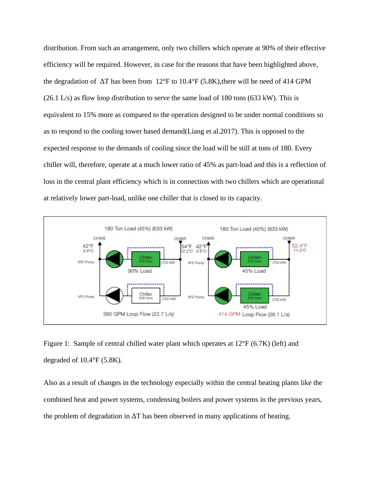
central chilled water plant that is equipped with two 200-ton chillers arranged in parallel. In case
each of the units is served by a specially dedicated water pump under control of drive that has a
variable frequency, the impacts will be evident. The plant is assumed to be operating at 12°F
(6.7K) ΔT which exist between the return temperature and chilled water supply,180 ton(633Kw)
load which is in such a way that 45% being part load. This results in 360 GPM flow of loop
distribution. From such an arrangement, only two chillers which operate at 90% of their effective
efficiency will be required. However, in case for the reasons that have been highlighted above,
the degradation of ΔT has been from 12°F to 10.4°F (5.8K),there will be need of 414 GPM
(26.1 L/s) as flow loop distribution to serve the same load of 180 tons (633 kW). This is
equivalent to 15% more as compared to the operation designed to be under normal conditions so
as to respond to the cooling tower based demand(Liang et al.2017). This is opposed to the
expected response to the demands of cooling since the load will be still at tons of 180. Every
chiller will, therefore, operate at a much lower ratio of 45% as part-load and this is a reflection of
loss in the central plant efficiency which is in connection with two chillers which are operational
at relatively lower part-load, unlike one chiller that is closed to its capacity.
Figure 1: Sample of central chilled water plant which operates at 12°F (6.7K) (left) and
degraded of 10.4°F (5.8K).
Also as a result of changes in the technology especially within the central heating plants like the
combined heat and power systems, condensing boilers and power systems in the previous years,
the problem of degradation in ΔT has been observed in many applications of heating.
AIM
To analyze the existing system of chilled- water in order to reveal its performance dependency
on the individual components of the same parts.
SPECIFIC OBJECTIVES
To alleviate degradation of ΔT challenges in National University of Singapore by the use
of control valves which are advanced pressure-independent?
To quantify the achieved improvement
To provide other recommendations based on the analyzed situation.
METHODOLOGY
Data Collection
Chiller Loads
In National University of Singapore central chilled –water system is made up of 30400 tons
(107MW). These were electric centrifugal chillers which work on the basis of the absorption.
Operating Temperatures (Condenser water temperature)
An internal study which was carried out in the recent time indicated that the ΔT of the plant has
been as low as 2°F (1.1K). This translates to an average annual parameter approximate of ΔT as
6°F (3.3K).
Chilled Water Operating Temperatures
The operation temperature of chilled water was at 2°F (1.1K)..
CHWS/R flow rate
The CHWS/R flow rate as estimated from the installed flow metres is 1400L/s.
Secure Best Marks with AI Grader
Need help grading? Try our AI Grader for instant feedback on your assignments.
Power Consumption
The annual power consumption of the plant was estimated to be (107MW).
Flow rates (Condenser water flow rates)
Other than the number of coils of the fans, the structure (Library) is being conditioned by at least
six air handlers with the capacity ranging from 7500 to 30000 cfm. This is equivalent to the flow
rate of the condenser as 3540 to 14 160L/s.
Plant Efficiency
The power operation efficiency was estimated to be between 40% and 80%.
Retrofit project description
The main library on the National University of Singapore has a there story 153,000 gross square
foot. This an approximate of 14286m2.The building was actually constructed in the year 1968.
Other than the number of the fan coils, this particular structure is conditioned by at least six
handlers of air with the capacity ranging from 7500 to 30000 cfm .
This is equivalent to (3,540 to 14,160 L/s). As already indicated, the majority of the handlers of
air are averaged at 6°F (3.3K) for coil ΔT. The main cause of the low value of ΔT was
overpumping on the coils. In order to have this particular situation improved there was testing of
two control strategies. In the initial stages, there was testing of two air handlers. One of the
testings involved the use of the strategy of a ΔT control which is conventionally applied to new
motorize. For the one which is pressure dependent, the deteriorated valve was replaced by a
globe valve(Mohan et al 2016). The last case was the use of pressure independent valves of ΔT
control types and were occurring in pairs. The use of two tandem valves was to ensure that the
flow rate for the coil exceeded the pressure independent valve capacities(Shen et al 2013).
During this particular time, the valves were never equipped with the meters of the flow which
today form part of the intelligent control valve. Instead, the system used was a mechanical
independent pressure control mechanism. In order to allow for the comparison between the
pressure dependent and pressure independent valves, a new globe valve was installed. All the
entire valves on the handlers of air used the same strategy of a ΔT control(Foo et al 2014). In
either approach, there was an increase in the ΔT of the handlers of air from certain values to 12°F
(6.7K). The arrangement of the pressure independent gave a proper control which was evident by
standard deviation which was as small as 0.7°F (0.4K). This value has been small when
compared to the values of standard deviation in the case of the pressure-dependent valves which
is 1.5°F (0.8K). It was, therefore, possible to conclude that both the management of ΔT as a
strategy as well as pressure independence were crucial in getting the most successful and
consistent result.
A larger pressure independent valve with the strategy of ΔT has in the meantime become
available. The other four air handlers remaining together with the one that uses a new valve of
the globe were taken through retrofitting program before they could be tested with the new
intelligent valves for the control. The air handling unit which is commonly known as AHU-5
equipped with the manager of ΔT and mechanically pressures independent valve was just left in
the present state configuration since the performance of the set up was found to be okay(Paiva et
al.2012). Considering that the same arrangement of the valve lack flow measurement which is
accurate as per the intelligent control valve, it was not included in the detailed analysis of the
data(Foo et al 2014).
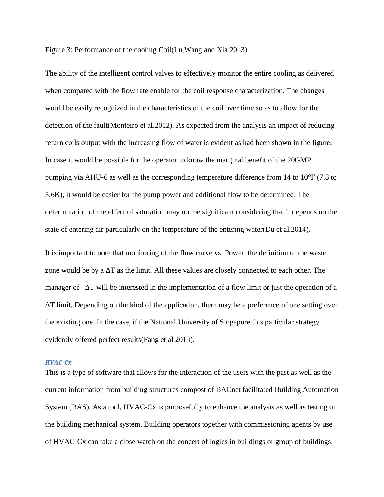
A sketch of the prototypical retrofit is as indicated below. In the sketch, there is an illustration of
the cooling coil in a unit of air handling that has been equated with the intelligent valve control
which is operated through analog signal input from the automation system of the building just
like for the case of any other kind of the valve. In order to allow for the evidence acquisition on
the valve performance during the experimental study, there was the connection of each and every
valve to a dedicated laptop, wireless internet connection to allow for remote maintenance and
monitoring and software of the data acquisition(Grohman 2014).
Figure 2: Set up of the case study experimental evaluation together with the intelligent control
valve(Lu,Wang and Xia 2013).
Data Processing
As illustrated in the figure below, finding for National University of Singapore coils for cooling
labeled as AHU-6 has been indicated as cooling power vs. flow rate of water. The data was
Paraphrase This Document
Need a fresh take? Get an instant paraphrase of this document with our AI Paraphraser
collected by the use of the control valve and not a separate system of data acquisition. The
cooling power increases from 0 to 300 KBtu/h which is equivalent to (0 to 88 kW) as the flow
increases from 0 to 60 GPM (0 to 3.8 L/s). This, however, translates into exponential decay
behavior(Lu,Wang and Xia 2013). Although there was the provision of the first 20GPM (1.3L/s)
which is roughly 180kBtu/h (53kW), the last 20 GPM ranged from to 60 from 40 GPM which is
equivalent to (2.6 to 3.8 L/s). This is equivalent to an increased value of 12kW. The difference of
the waterside temperatures which roughly starts from roughly 25°F (14K) significantly drop with
the flow rate increase to a value of say 5°F (2.8K). This is the same as the inverse trend to the
power of cooling(Mantilla et al 2014). Both waterside temperatures and thermal temperature
power difference show the behavior which is expected from the coil evaluation as indicated in
the figure below.
Figure 3: Performance of the cooling Coil(Lu,Wang and Xia 2013)
The ability of the intelligent control valves to effectively monitor the entire cooling as delivered
when compared with the flow rate enable for the coil response characterization. The changes
would be easily recognized in the characteristics of the coil over time so as to allow for the
detection of the fault(Monteiro et al.2012). As expected from the analysis an impact of reducing
return coils output with the increasing flow of water is evident as had been shown in the figure.
In case it would be possible for the operator to know the marginal benefit of the 20GMP
pumping via AHU-6 as well as the corresponding temperature difference from 14 to 10°F (7.8 to
5.6K), it would be easier for the pump power and additional flow to be determined. The
determination of the effect of saturation may not be significant considering that it depends on the
state of entering air particularly on the temperature of the entering water(Du et al.2014).
It is important to note that monitoring of the flow curve vs. Power, the definition of the waste
zone would be by a ΔT as the limit. All these values are closely connected to each other. The
manager of ΔT will be interested in the implementation of a flow limit or just the operation of a
ΔT limit. Depending on the kind of the application, there may be a preference of one setting over
the existing one. In the case, if the National University of Singapore this particular strategy
evidently offered perfect results(Fang et al 2013).
HVAC-Cx
This is a type of software that allows for the interaction of the users with the past as well as the
current information from building structures compost of BACnet facilitated Building Automation
System (BAS). As a tool, HVAC-Cx is purposefully to enhance the analysis as well as testing on
the building mechanical system. Building operators together with commissioning agents by use
of HVAC-Cx can take a close watch on the concert of logics in buildings or group of buildings.
The testing process can be conducted by use of passive surveillance of operation system or
through the use of customizable test scripts for an active testing for the case of BACnet-enabled
Building Automation System issuing command to the system concerning the different normal
operational modes and then employ the use of expert rules which can detect any operation within
the system which is not proper(Foo et al 2014).
The analysis is conducted through taking records on the device data compost of motors, sensors,
alarms, dampers as well as BAS condition of the mode and then employ a logical set of expert
rules to determine improper operations within the system. The logical rules are extracted from
the determination of presumed values in the course of operational modes, from expectations
written down in the operational documented sequence, and also from the reports on recorded
faults as well as alarms from these devices. In case the conditional rule goes through, a detection
alarm for the fault engendered and then the major source of the fault is availed to the user to
conduct extra diagnostic assistance(Capozzoli and Primiceri 2015).
The obtained values are compared as per the minutes and the readings are examined to ascertain
the mode of operation and then employ rules that help verify if the values are consistent to the
operational mode or if they are far away from the set point. A diagnostic report is then made and
presented through the graphical user interface (GUI) in HVAC-Cx. The presented diagnostic
report illustrates the occurrence of the fault in one minute, one hour as well as an average within
a single day. The might of HVAC-Cx graphic enables the user to be capable of viewing at the
presented data and then give extra insight. The methods of detection, as well as diagnostic, were
initially generated to be applied in the single duct Variable Air Volume (VAV) together with
constant volume Air Handling Units (AHUs).
Secure Best Marks with AI Grader
Need help grading? Try our AI Grader for instant feedback on your assignments.
In the past few years, a new series of expert rules were established to evaluate the execution of
chiller loops through the use of data obtained from the prevailing BAS sensors. The range of
operation of chiller loop is greatly minimized by the existence of data design (such as strategy
sequencing as well as control requirements) together with operational data consisting of
escalations by the sensors, values of the set points and control signals. The accuracy of the
commercial standardized sensors designed for the purpose of control is efficiently high to
evaluate the performance. There are a set of rules that are provided by the HVAC-Cx which can
be used in compliance with the possibility of establishing custom rules. After the configuration,
the users can, therefore, obtain relevant values from the historical information with a lot of ease
or make some rules to guide such historical data(Foo et al 2014).
The various chiller loop rules have been categorized into four groups including the temperature
correlation, potential safety issues, control logic, and parametric values. The initial eight rules
include the return temperature, constructing the supply of chilled water, and parametric
supervision of the chilled water plant(Cuce, Young & Riffat 2014). These weigh the data
obtained in a minute and the scope of accepted values that were specifically configured for the
system. The other rules starting from 9 up to 19 are as per the expectations on temperature
correlation that has to be retained in the course of normal performance. The operation may fail to
meet the intended purpose in case of violation of such correlations.
Life Cost assessment
Based on the modifications that are evident in the whole system, it was possible to produce the
estimates as per the cost of the construction or installation especially for the case of the lower
pre-investment cost. The used values have been based on the anticipated modifications of the
plant.
Least Investment
Capture
Changes in the costs
as expressed in
percentages
The layout of the
system
Longer ducts 4% higher prices/cost
estimates
Area of the site Allowance of the
space for the
compression tools or
equipment
8% high prices/costs
for the maintenance in
the site
Primary components Variation Absence
The corresponding changes in the percentages in the cost for the higher investment have been
extracted from the existing data values(Kim et al 2013).
FINDINGS AND RECOMMENDATIONS
System selection looking at part load and full load conditions based current improved trend of
technologies
The discoveries, as well as the recommendations which were made as per the evaluation which
was carried on the system, are eight in number.
The first discovery or finding: The setpoint cannot be maintained by a chilled water loop
The analysis conducted through HVAC-Cx showed that there could not be consistent
maintenance of the set point by the chilled water loop. The 12th rule clearly indicated that the
temperature of the chilled water supply for the plant (Twcps) falls below the recommended values
for the first 15 days out of the total 19 days for the month of July and daily in August(Feng et al
2014). In addition to that, the 13th rule clearly shows that the temperature of the chilled water
supply for the plant (Twcps) is raised above the recommended values and the failure arose on the
tenth day out of the total 19 days on the information in the month of July and for 8 days in
August. The threshold temperature required to trigger the fault was maintained at 4 0C which is
equivalent to 39.2 0F. In case of violation of the rules, the diagnostic report shows the likelihood
of error for either the sensor for temperature or the control logic. Violation of the 6th rule was
reported as well by the HVAC-Cx which showed that the temperature of the chilled water supply
for the plant (Twcps) sensor does not fall within the range(Hu et al 2015).
In case there is a significant increase in the temperature of the chilled water supply for the plant
(Twcps) over the temperature for the building supply of chilled water (Twcbs, sp), AHUs that relies
heavily on the chilled water for the purpose of cooling the conditioned voids become unstable.
The fault is likely to pose a direct effect on the consolation of the residents and therefore rise in
the complaints in the matters of comfort by the occupants. For that reason, putting into
consideration the complaints raised by the occupants becomes one among the primary objectives
of the project. The AHUS control may as well become unstable if there is a significant fall in
temperature for the building supply of chilled water (Twcbs) to the levels below (Twcbs, sp). In case
this takes place at day time in the 3rd mode, the campus loop is effectively precooled by the
chiller, which for the case is ineffective in terms of cost(Sun, Feng and Wang2015). In addition
to that, an extreme drop in temperature may facilitate the freezing of the coil which will
automatically set off the action of defrosting. This reflects a reduced demand in the cost of
energy(Barreca & Fichera 2016).
First Recommendation
Determine the temperature sensor of the supply for the building chilled water (Twcbs) and then
conduct an investigation on the efficiency of the selected mode of operation as the initial
supervision on the control logic.
Paraphrase This Document
Need a fresh take? Get an instant paraphrase of this document with our AI Paraphraser
2nd Finding:
Mode 3b continuous operations
There was an indication by the BAS that the chiller was operating continuously in the mode of
3b. The operation of the chiller in this mode is to provide cooling for the campus loop and
building and both the building pump and the chiller pump are activated.
The set point for the discharge was set at 7.22°C (45°F). In July, when the system is operating at
3b mode, the building should be meeting its cooling load with the chiller which is dedicated and
the chiller should be able to effectively provide supplementary cooling to the plant loop centrally
located. The chiller was instead unable to meet the load of cooling and to effectively bring the
temperature down to its set point(Tirmizi et al.2014). This was reported by the facility manager
from the month of May to September when the chiller of the building was supposed to be used as
a backup in ensuring that the cooling load of the building is met in the evening hours when the
chilling loop centrally located begins making ice. In other words, the operation of the building
was continuously in 3b Mode.
Recommendation 2
The operating mode is to be changed immediately to mode 4 that can effectively shift the
chiller’s control so that it is specifically dedicated to meeting the load of the building
only(Audenaert, De Cleyn & Buyle 2012). This will go alongside the investigation of the reason
why the system is not directly operating off the loop of the University in Mode 2b or 2a. It was
discovered that the strainers had not been cleared off particles of clay material which had
contaminated the loop during the repair of the line leading to the coil fouling as well as inhibition
of the necessary flow rate for effective transfer of heat. Hence, the operators of the buildings
reduced the set point of the chiller to have the loop maintained at 3.3°C (38°F) in building
cooling and finally moved to the operation of 24hours due to the slow response times.
Figure 4: High-level summary of the number of detected faults as per the HVAC-Cx in July and
August 2015(Lu,Wang and Xia 2013)
Finding 3 Improper Control of Valves
Analysis of the status of the pumps and valves by the use of HVAC-Cx indicated a violation of
certain fundamental rules and principles. There was an indication that valve 2, as well as valve 3,
has been operating out of the sequence as followed. In particular, the valves shaded in the table
had their positions reversed for the data of Mode 3b with the closed V-3 and opened V-2. Such
status is directly in conflict with the documentation of the design and as per the documentation
provided by the contractor responsible for the control. On the visit to the field, it was discovered
that the existence of error was in documentation rather than in the implementation of the control
logic(Wallaert et al.2014).
Recommendation 3
System documentation update as well as making required corrections in the rule list of the
HVAC-Cx
System Proofing
Out of Range temperature of the plant chilled –water supply
The temperature of the plant chilled water supply commonly marked as Twcps was found to be
consistently having a reading of 21°C (69.8°F) as illustrated in figures 3 and 6. The axis that has
been provided clearly shows the values of the temperatures in degrees Celsius. As per these
figures, there was a violation of rule 5 showing that the reading of the temperatures was above
the range expected. This kind of temperature has been marked high in meeting the temperature of
the supply as per the requirements of the PAC buildings(Calise et al.2016).
As can be seen from the HVAC-Cx graphs, it is very clear that the supply of the building, as
well as temperatures of the return(Twcbs andTwcb), are tracking similar fluctuation in temperatures
as exhibited by the supply temperatures of the plant with a magnitude which was not reasonable.
During the visit to the field, the approximate reading of the BAS sensor was approximated at
21°C (70°F) while another analog sensor of the temperature indicated the temperature to be at
7.2°C (45°F). This was as per the confirmation by the staff responsible for the maintenance to be
consistency with the temperature of the campus loop system at that particular time(Grohman et
al.2014).
There was no impact on the energy use in the building since the reading of the sensor as
displayed by BAS is not an input into the sequence control for activating the chiller system of the
building. The solution for this particular problem to ensure that there is system proofing will be
checking for the sensors of temperatures of the supply marked as Twcps to ensure that there is
proper calibration and to do replacement where it is deemed fit(Wang et al.2015).
Table: Pump and Valve Sequencing Inconsistency in the Loop of Chilled-Water system.
Secure Best Marks with AI Grader
Need help grading? Try our AI Grader for instant feedback on your assignments.
Figure 5: Graphical illustration of the capabilities of HVAC-Cx showing temperatures of the
system as well as the command signals. The plant chilled water supply has been labeled as
4(Lu,Wang and Xia 2013).
Life Cost assessment
The general cost in the system modification
The incremental cost for modification so as to factor in the changes which have been
recommended is the same as making every area to be captured ready. The strategy for capture
readiness allowed for the estimation of the highest values as well as the least values as the
process rolls out.
Figure 6: The system layout of Chilled water(Du et al. 2014)
From the table that has been shared above, it is clear that only the area that has costs relatively
low is the ducts and the stacks. The additional costs as per the recommendations, when compared
Auxilliary
From the table that has been shared above, it is clear that only the area that has costs relatively
low is the ducts and the stacks. The additional costs as per the recommendations, when compared
Auxilliary
to the previous digit, are equal to 0.3%. The additional cost is thus meant to ensure that the
efficiency of the system is improved(Grohman et al.2014).
CONCLUSION
The study objective which involved evaluation of the chilled water system of the National
University of Singapore was achieved by the use of automated commissioning tool. The
evaluation of the tool was done by the use of the field data which was obtained from a building
located within the university (Library). The collection of the data was done for at least four
weeks in August and July in the year 2019 under the typical operation of the building itself.
The study or the evaluation of the chilled water system of the school library building revealed
several faults through the software of the HVAC-Cx. One of the limitations of the approach
which was used was that it is dependent on the fluctuation of weather which occurs seasonally as
well as the response of the system while capturing the variety of the modes of operations. The
monitoring process of the system performance was able to detect two faults out of the four
modes of operations. Through consideration of the historical data as well as the performance of
active testing, it will be possible for the researchers to effectively evaluate the operations of the
systems in a more systematic and complete manner(Abdel-Salam, Ge, and Simonson 2013).
The tests conducted by the use of the passive surveillance showed that the common faults within
the chilled water system or just HVAC can be detected by HVAC-Cx successfully while utilizing
the right data(Ali et al 2013). The improvement of the performance is likely to be increased
when the rule base is expanded so as to effectively capture the faults which have been inserted
manually. The used tool in the case study presently has the capabilities of performing active
testing and monitoring the chiller loops. It is capable to provide a simple user interface which
Paraphrase This Document
Need a fresh take? Get an instant paraphrase of this document with our AI Paraphraser
creates custom rules and considers the historical data for values which are relevant. The case
study was generally a success. The findings from the monitoring processes of the system
performance identified several important improvements in the performance. Such findings,
therefore, became the basis of the initiative by the manager to have completed retro-
commissioning of energy project at the site in the field while using HVAC-Cx to assist in
supporting investigation as well as testing in the field.
REFERENCES
Abdel-Salam, A.H., Ge, G. and Simonson, C.J., 2013. Performance analysis of a membrane
liquid desiccant air-conditioning system. Energy and Buildings, 62, pp.559-569.
Ali, M., Vuckovic, V., Sahir, M.H. and Fontanella, G., 2013. Energy analysis of chilled water
system configurations using simulation-based optimization. Energy and Buildings, 59, pp.111-
122.
Audenaert, A., De Cleyn, S. H., & Buyle, M. (2012). LCA of low-energy flats using the Eco-
indicator 99 method: Impact of insulation materials. Energy and Buildings, 47, 68-73.
Barreca, F., & Fichera, C. R. (2016). Thermal insulation performance assessment of
agglomerated cork boards. Wood Fiber Sci, 48(2), 1-8.
Calise, F., Acadia, M.D., Macaluso, A., Piacentino, A., and Vanoli, L., 2016. Exergetic and
exergoeconomic analysis of a novel hybrid solar-geothermal polygeneration system producing
energy and water. Energy conversion and management, 115, pp.200-220.
Capozzoli, A. and Primiceri, G., 2015. Cooling systems in data centers: state of art and emerging
technologies. Energy Procedia, 83, pp.484-493.
Cho, K., Hong, Y., & Seo, J. (2014). Assessment of the economic performance of vacuum
insulation panels for housing projects. Energy and Buildings, 70, 45-51.
Cuce, E., Young, C. H., & Riffat, S. B. (2014). Performance investigation of heat insulation solar
glass for low-carbon buildings. Energy Conversion and Management, 88, 834-841.
Du, Z., Fan, B., Jin, X. and Chi, J., 2014. Fault detection and diagnosis for buildings and HVAC
systems using combined neural networks and subtractive clustering analysis. Building and
Environment, 73, pp.1-11.
Fang, L., Cotton, I., Wang, Z. J., & Freer, R. (2013, June). Insulation performance evaluation of
high-temperature wire candidates for aerospace electrical machine winding application. In 2013
IEEE Electrical Insulation Conference (EIC) (pp. 253-256). IEEE.
Feng, H., Chen, L., Xie, Z., & Sun, F. (2014). Constructal entransy dissipation rate minimization
for the variable cross-section insulation layer of the steel rolling reheating furnace wall.
International Communications in Heat and Mass Transfer, 52, 26-32.
Foo, D.C., Ng, D.K., Leong, M.K., Chew, I.M., Subramaniam, M., Aziz, R. and Lee, J.Y., 2014.
Targeting and design of chilled water network. Applied energy, 134, pp.589-599.
Grohman, W. and Filbeck, A., Lennox Industries Inc, 2014. Device abstraction system and
method for a distributed architecture heating, ventilation and air conditioning system. U.S.
Patent 8,661,165.
Grohman, W., Lennox Industries Inc, 2014. Device abstraction system and method for a
distributed-architecture heating, ventilation and air conditioning system. U.S. Patent 8,855,825.
Hu, B., Li, Y., Cao, F. and Xing, Z., 2015. Extremum seeking control of COP optimization for
air-source transcritical CO2 heat pump water heater system. Applied Energy, 147, pp.361-372.
Kim, S., Seo, J., Cha, J., & Kim, S. (2013). Chemical retreating for gel-typed aerogel and
insulation performance of cement containing aerogel. Construction and Building Materials, 40,
501-505.
Secure Best Marks with AI Grader
Need help grading? Try our AI Grader for instant feedback on your assignments.
Leong, Y.T., Tan, R.R., Aviso, K.B. and Chew, I.M.L., 2016. Fuzzy analytic hierarchy process
and targeting for inter-plant chilled and cooling water network synthesis. Journal of Cleaner
Production, 110, pp.40-53.
Liang, Y., Wu, H., Huang, G., Yang, J., & Wang, H. (2017). Thermal performance and service
life of vacuum insulation panels with aerogel composite cores. Energy and Buildings, 154, 606-
617.
Lu, Z., Wang, R. and Xia, Z., 2013. Experimental analysis of an adsorption air conditioning with
micro-porous silica gel–water. Applied Thermal Engineering, 50(1), pp.1015-1020.
Mantilla, J. D., Gariboldi, N., Grob, S., & Claessens, M. (2014, June). Investigation of the
insulation performance of a new gas mixture with extremely low GWP. In Electrical Insulation
Conference (EIC), 2014 (pp. 469-473). IEEE.
Mohan, G., Kumar, U., Pokhrel, M.K. and Martin, A., 2016. A novel solar thermal
polygeneration system for sustainable production of cooling, clean water and domestic hot water
in the United Arab Emirates: Dynamic simulation and economic evaluation. Applied
Energy, 167, pp.173-188.
Monteiro, C. R. A., Marino, C. M., Torchia, F., Nannipieri, E., Robertson, N., Smith, R. S., &
Machimbarrena, M. (2012). Comparative analysis of airborne sound insulation field
measurements using different ISO 717-1 performance descriptors-Lightweight separating walls
and floors. Proceedings of Euronoise, Prague, Czech Republic, 1202-1207.
Paiva, A., Pereira, S., Sá, A., Cruz, D., Varum, H., & Pinto, J. (2012). A contribution to the
thermal insulation performance characterization of corn cob particleboards. Energy and
Buildings, 45, 274-279.
Shen, L., Xiao, F., Chen, H. and Wang, S., 2013. Investigation of a novel thermoelectric radiant
air-conditioning system. Energy and buildings, 59, pp.123-132.
Shi, J., Lu, L., Guo, W., Sun, Y., & Cao, Y. (2013). An environment‐friendly thermal insulation
material from cellulose and plasma modification. Journal of Applied Polymer Science, 130(5),
3652-3658.
Sun, J., Feng, X. and Wang, Y., 2015. Cooling-water system optimisation with a novel two-step
sequential method. Applied Thermal Engineering, 89, pp.1006-1013.
Tirmizi, S.A., Siddiqui, O.K., Gandhidasan, P. and Zubair, S.M., 2014. Performance analysis of
an ejector cooling system with a conventional chilled water system. Applied Thermal
Engineering, 66(1-2), pp.113-121.
Wallaert, T., Thorson, T.H. and Pavlak, T.G., Lennox Industries Inc, 2014. Flush wall mount
thermostat and in-set mounting plate for a heating, ventilation and air conditioning system. U.S.
Patent 8,802,981.
Wang, J.J., Yang, K., Xu, Z.L. and Fu, C., 2015. Energy and exergy analyses of an integrated
CCHP system with biomass air gasification. Applied energy, 142, pp.317-327.
Xiao, F. and Fan, C., 2014. Data mining in building automation system for improving building
operational performance. Energy and buildings, 75, pp.109-118.
Yan, C., Shi, W., Li, X. and Zhao, Y., 2016. Optimal design and application of a compound cold
storage system combining seasonal ice storage and chilled water storage. Applied energy, 171,
pp.1-11.
Zeigler, T.A., Bracey, J.S., Connell, B.S. and Sloan, S., Bergstrom Inc, 2013. Combined heating
and air conditioning system for vehicles. U.S. Patent 8,517,087.
storage system combining seasonal ice storage and chilled water storage. Applied energy, 171,
pp.1-11.
Zeigler, T.A., Bracey, J.S., Connell, B.S. and Sloan, S., Bergstrom Inc, 2013. Combined heating
and air conditioning system for vehicles. U.S. Patent 8,517,087.
1 out of 28
Related Documents
Your All-in-One AI-Powered Toolkit for Academic Success.
+13062052269
info@desklib.com
Available 24*7 on WhatsApp / Email
Unlock your academic potential
© 2024 | Zucol Services PVT LTD | All rights reserved.