Ask a question from expert
Optimizing a Solution to a Modelling Problem
8 Pages4115 Words281 Views
Added on 2019-09-13
Optimizing a Solution to a Modelling Problem
Added on 2019-09-13
BookmarkShareRelated Documents
U08079 Coursework 2017Optimizing a solution to a modelling problemFor the coursework you are required to design, implement and optimise a program to solve resistor networks.A basic example Jacobi program is provided but this program is inefficient andyou are required to improve it. You should make use of a range of code optimisation techniques and verify their effectiveness using benchmarking. You may need to create and solve some reasonably large resistor networks todemonstrate the effectiveness of some of the optimisations.In addition to optimising the program on a single PC, you are also required to implement a version of your program on the department HAC cluster using message passing with MPI in order to investigate possible speedup and other optimisations by employing multiple processes running on multiple processors.The ProblemA resistor is an electronic component that reduces the current and voltage of an electrical signal. The diagram below shows a number of resistors forming an electronic circuit. The green boxes represent resistors and the lines represent wires (or nodes) connecting them together. Each resistor has a value, in ohms, showing how powerful a resistor it is. More ohms means a more powerful resistor, which resists more, and thus lowers voltage further.The problem is to calculate the voltages at nodes v2 and v3. Note the left node is connected to a fixed 6 volt supply and the right node is connected to fixed 0 volts. There are two relevant electrical laws we can use to solve this problem:Kirchhoff’s Law: the net current at a node is zero, so current in must equal current out at each circuit node. (Note that current is not the same as voltage.)Ohm’s Law: If a resistor has a resistance of R ohms, and the voltage across the resistor (i.e. the difference between the input and output voltages) is V volts, then the current flowing through the resistor is I=V/R amps.You can also utilise the fact that current flows from points of high voltage to points of low voltage.C Cox 21.2.201716336vV2V30v
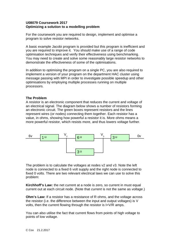
Using these laws, we can derive a system of equations which we can then solve to give the voltages v2 and v3.Hand calculation for the above example:Node v2 has an input from the 1 ohm resistor.By Ohm’s law the current in from this resistor is (6-v2)/1 (6 is the input voltage, v2 is the node voltage which we want to find, and 1 is the ohm rating of the resistor.)Node V2 outputs to the 6 ohm and the 3 ohm resistor.By Ohm’s law the current out to the 6 ohm resistor is (v2-v3)/6,and the current out to the 3 ohm resistor is (v2-v3)/3.By Kirchhoff’s law the current at the inputs and outputs of V2 must be the same, so (6-v2)/1 = (v2-v3)/6 + (v2-v3)/3At node v3 we consider the inputs and outputs similarly:The two input resistors will have currents of (v2-v3)/6 and (v2-v3)/3and the output resistor will have a current of (v3-0)/3.So (v2-v3)/6 + (v2-v3)/3 = (v3-0)/3.Now we have two equations to solve simultaneously:(6-v2)/1 = (v2-v3)/6 + (v2-v3)/3(v2-v3)/6 + (v2-v3)/3 = (v3-0)/3.Simplifying the first equation:Start with(6-v2)/1 = (v2-v3)/6 + (v2-v3)/3Dividing by one does nothing(6-v2) = (v2-v3)/6 + (v2-v3)/3Multiply all by 6 to remove /66(6-v2) = (v2-v3) + 2(v2-v3)Carry out multiplications36 – 6v2 = v2-v3 + 2v2 – 2v3Collect terms36 – 6v2 = 3v2 – 3v3Add 6v2 to both sides, to move it 36 = 9v2 – 3v3Divide through by 3 to lower numbers12 = 3v2 – v3Same with the second equation:Start with(v2-v3)/6 + (v2-v3)/3 = (v3-0)/3Subtracting 0 does nothing(v2-v3)/6 + (v2-v3)/3 = v3/3Multiply all by 6 to remove /6(v2-v3) + 2(v2-v3) = 2v3Carry out multiplicationsv2-v3 + 2v2 – 2v3 = 2v3Collect terms3v2 – 3v3 = 2v3Subtract 2v3 from both sides 3v2 – 5v3 = 0We now have two equations of the form: 3v2 – 1v3 = 12 3v2 – 5v3 = 0Which we can easily solve as a simultaneous equation as v2=5 and v3=3Notice that for a general resister network:We will end up with one equation per node;Each of these equations will have one v term for each node voltage.C Cox 21.2.2017
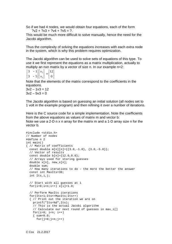
So if we had 4 nodes, we would obtain four equations, each of the form ?v2 + ?v3 + ?v4 + ?v5 = ?.This would be much more difficult to solve manually, hence the need for the Jacobi algorithm.Thus the complexity of solving the equations increases with each extra node in the system, which is why this problem requires optimization.The Jacobi algorithm can be used to solve sets of equations of this type. To use it we first represent the equations as a matrix multiplication, actually to multiply an nxn matrix by a vector of size n. In our example n=2:012531332vvNote that the elements of the matrix correspond to the coefficients in the equations.3v2 – 1v3 = 123v2 – 5v3 = 0The Jacobi algorithm is based on guessing an initial solution (all nodes set to 1 volt in the example program) and then refining it over a number of iterations.Here is the C source code for a simple implementation. Note the coefficients from the above equations as values of matrix m and vector b:Note we use a 2-D n x n array for the matrix m and a 1-D array size n for the vector b.#include <stdio.h>// Number of nodes#define n 2int main(){ // Matrix of coefficientsconst double m[n][n]={{3.0,-1.0}, {3.0,-5.0}}; // Vector of resultsconst double b[n]={12.0,0.0}; // Arrays used for storing guessesdouble x[n], new_x[n];double sum; // How many iterations to do – the more the better the answerconst int MaxIts=30;int Its,i,j;// Start with all guesses at 1for(i=0;i<n;i++) x[i]=1.0; // Perform MaxIts iterationsfor(Its=1;Its<=MaxIts;Its++){ // Print out the iteration we are on printf("Its=%d",Its); // This is the actual Jacobi algorithm // Calculate our next round of guesses in max_i[]for(i=0; i<n; i++){ sum=0.0;for(j=0;j<n;j++)C Cox 21.2.2017
End of preview
Want to access all the pages? Upload your documents or become a member.
Related Documents
Fundamentals of Electrical and Electronicslg...
|19
|2814
|203
Lab 2 Report: Circuit Fundamentalslg...
|7
|1008
|136
Charging and discharging a Capacitor Assignment 2022lg...
|14
|1598
|29
Solved Electrical Circuit Problems with Calculations and Formulaslg...
|21
|819
|197
Lab Report 1: Electrical Circuit Measurementslg...
|5
|954
|486
Electrical and Electronics Principles - PDFlg...
|17
|890
|80