IMAT5205 Coursework: Analysis and Design with UML Diagrams
VerifiedAdded on 2023/05/28
|8
|1896
|483
Report
AI Summary
This report presents a comprehensive analysis of a systems analysis and design assignment, focusing on the creation and evaluation of UML diagrams. The report includes detailed descriptions and diagrams of an analysis class diagram, a communication diagram, and a sequence diagram, all crucial for visualizing the static and dynamic aspects of a system. The diagrams were created using Enterprise Architect, a CASE tool, and the report discusses the design decisions made during the modelling process to ensure the system's requirements are met. Furthermore, the report evaluates the usefulness of UML diagrams and CASE tools throughout the software development lifecycle, highlighting their importance in the planning, analysis, design, implementation, and maintenance phases. The report emphasizes the benefits of using CASE tools for automating the software development process, enhancing project documentation, and improving collaboration among project teams.

Paraphrase This Document
Need a fresh take? Get an instant paraphrase of this document with our AI Paraphraser
Contents
Analysis class diagram.................................................................................................................................2
Description..............................................................................................................................................2
Add new tour class diagram....................................................................................................................2
Decisions.................................................................................................................................................2
Communication diagram.............................................................................................................................3
Description. . . . . . . . . . . . . . . . . . . . . . . . . . . . . . . . . . . . . . . . . . . . . . . . . . . . . . . . . . . . . . . . . . . . . . . . . . . . 3
Add new tour use case communication diagram.....................................................................................4
Decisions.................................................................................................................................................4
Sequence diagram.......................................................................................................................................4
Description..............................................................................................................................................4
Add new tour use case sequence diagram..............................................................................................5
Decisions.................................................................................................................................................6
Evaluation....................................................................................................................................................6
References...................................................................................................................................................7
Analysis class diagram
Description
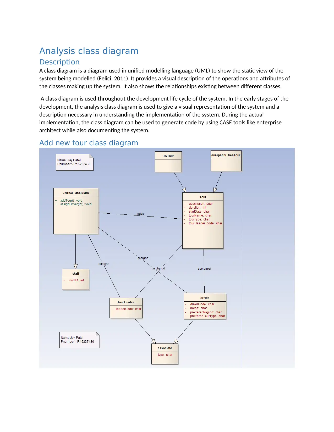
A class diagram is a diagram used in unified modelling language (UML) to show the static view of the
system being modelled (Felici, 2011). It provides a visual description of the operations and attributes of
the classes making up the system. It also shows the relationships existing between different classes.
A class diagram is used throughout the development life cycle of the system. In the early stages of the
development, the analysis class diagram is used to give a visual representation of the system and a
description necessary in understanding the implementation of the system. During the actual
implementation, the class diagram can be used to generate code by using CASE tools like enterprise
architect while also documenting the system.
Add new tour class diagram
⊘ This is a preview!⊘
Do you want full access?
Subscribe today to unlock all pages.

Trusted by 1+ million students worldwide
Decisions
To model the analysis class diagram, the following design decisions had to be made in order to make it
easy to implement the system ensuring the described requirements are met. The decisions made are;
For every time a tour is assigned a leader to act as the tour leader, the clerical assistant will have
to choose from a list of available leaders that will be retrieved from the database. The clerical
assistant can then choose one or more leaders if the tour requires more than one leader.
The tour company will be offering two types of tours to its clients; Europe tour and United
Kingdom tour. This two types of tours are obtained through specialization of the tour class
because they share attributes like description, duration, start date, leader of the tour and name
of the tour.
The company has two types of associates; a tour leader and a driver. This creates two classes
that are connected to the associate class through specialization.
Communication diagram
Description
A communication diagram is an interaction diagram that is used to show how objects interact in a
system. It’s extended from an object diagram and shows the passing of messages between objects
making up the system. Communication diagrams are very useful in unified modelling language. Some of
the uses of communication diagrams are;
By identifying objects in order to know the flow of messages, communication diagrams facilitate
identification of objects and their operations within a use case.
Communication diagrams are used in modelling alternative scenarios existing within a specific
use case of a system.
Communication diagrams help capture how objects interact and the role of the interaction
between the objects.
For the architectural design of a system, communication diagrams are very helpful in modelling
different mechanisms existing within the system.
Communication diagrams are helpful because they show the messages passing between objects
of a system and how the communication delivers functionalities of different use cases.
There is some similarity between communication diagrams and sequence diagrams because they all
show interaction between objects making up the system thus a communication diagram can be used to
help model a sequence diagram.
Paraphrase This Document
Need a fresh take? Get an instant paraphrase of this document with our AI Paraphraser
Add new tour use case communication diagram
Decisions
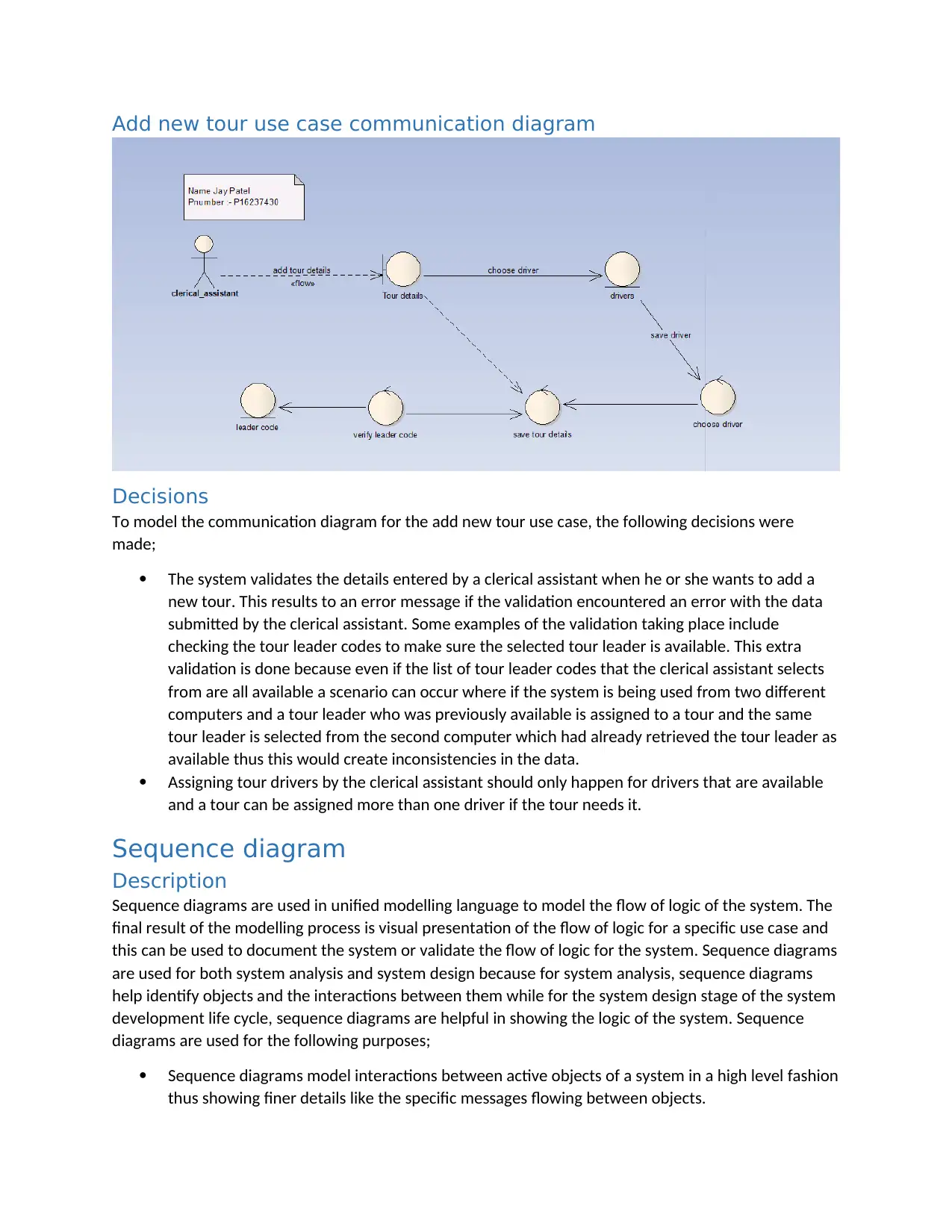
To model the communication diagram for the add new tour use case, the following decisions were
made;
The system validates the details entered by a clerical assistant when he or she wants to add a
new tour. This results to an error message if the validation encountered an error with the data
submitted by the clerical assistant. Some examples of the validation taking place include
checking the tour leader codes to make sure the selected tour leader is available. This extra
validation is done because even if the list of tour leader codes that the clerical assistant selects
from are all available a scenario can occur where if the system is being used from two different
computers and a tour leader who was previously available is assigned to a tour and the same
tour leader is selected from the second computer which had already retrieved the tour leader as
available thus this would create inconsistencies in the data.
Assigning tour drivers by the clerical assistant should only happen for drivers that are available
and a tour can be assigned more than one driver if the tour needs it.
Sequence diagram
Description
Sequence diagrams are used in unified modelling language to model the flow of logic of the system. The
final result of the modelling process is visual presentation of the flow of logic for a specific use case and
this can be used to document the system or validate the flow of logic for the system. Sequence diagrams
are used for both system analysis and system design because for system analysis, sequence diagrams
help identify objects and the interactions between them while for the system design stage of the system
development life cycle, sequence diagrams are helpful in showing the logic of the system. Sequence
diagrams are used for the following purposes;
Sequence diagrams model interactions between active objects of a system in a high level fashion
thus showing finer details like the specific messages flowing between objects.
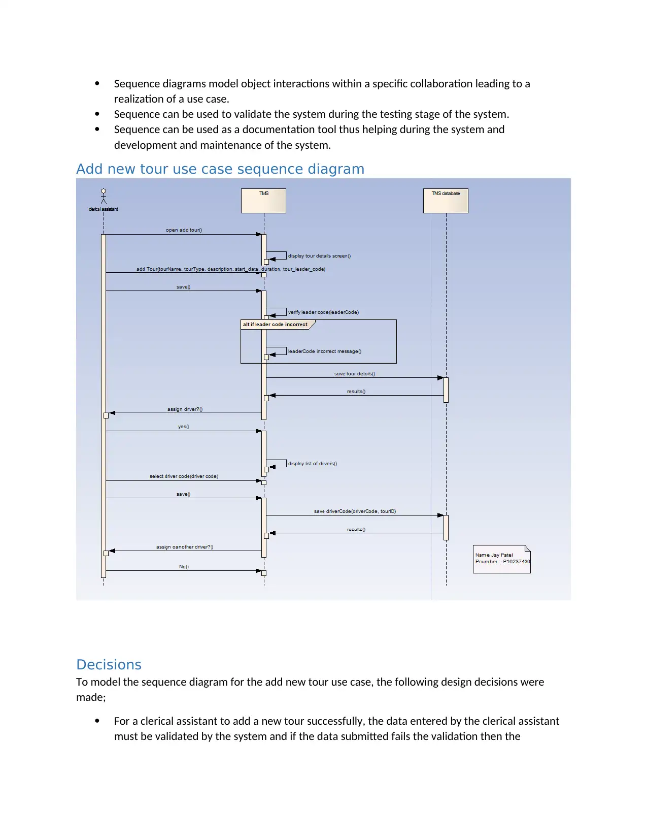
Sequence diagrams model object interactions within a specific collaboration leading to a
realization of a use case.
Sequence can be used to validate the system during the testing stage of the system.
Sequence can be used as a documentation tool thus helping during the system and
development and maintenance of the system.
Add new tour use case sequence diagram
Decisions
To model the sequence diagram for the add new tour use case, the following design decisions were
made;
For a clerical assistant to add a new tour successfully, the data entered by the clerical assistant
must be validated by the system and if the data submitted fails the validation then the
⊘ This is a preview!⊘
Do you want full access?
Subscribe today to unlock all pages.

Trusted by 1+ million students worldwide
application should show an error but if the data is validated successfully then the application
should add the new tour successfully.
For the tour leaders and the drivers, the clerical assistant can sign one or more for both of them
but the tour leader or the driver assigned to a new tour has to be available. Extra validation of
availability of a driver or a tour leader is done before saving the data to ensure that final data
saved at the end is consistent at all times
Evaluation
Case tools are computer application programs which are very useful in the automation of the software
development lifecycle. CASE tools are used at all the stages of the SDLC by either project managers,
project analysts and system developers and engineers to help in modelling, developing and
documenting the system (Krishnamurthy, n.d) . There are various CASE tools that are available for
modelling different stages of the software development life cycle including design tools, analysis tools,
database management tools, project management tools, documentation tools among other tools.
By using CASE tools in a project, the development of the project is accelerated significantly thus the final
result meets the expectation of both the client and the project team as each stage of the life cycle is
documented and validated by use of models and diagrams generated using CASE tools.
CASE tools can be divided into different parts based on how they are used for a specific stage of the
software development life cycle. These components are;
Central repository- CASE tools need a central repository that is intended to server as a source of
common, consistent and integrated information. The central repository is where all the
specifications of the system, software requirement documents including specification and
design documents, reports and diagrams are stored. It can act as the data dictionary of the
project.
Upper case tools- these type of tools are using in the planning of different stages, analysis of
each stage and the design of the stages making up the system.
Lowe case tools- These type of tools are used in implementation of the system, testing the
system by performing different types of tests including unit tests, integration tests, components
tests and system tests and finally for maintenance of the system.
Integrated case tools- Integrated case tools are very useful as they find uses in almost all stages
of the software development life cycle including the requirement gathering stage, testing stage
and the documentation stage of the project.
By using components defined above, a classification of various case tools comprises of the following;
Diagram tools- These type of CAASE tools are used to represent components of the system, data
and the flow of control among different components of the system and the structure of the
system in a graphical form.
Processing modelling tools- this tools are used to show the process model that is used to create
and develop the software.
Project management tools- these tools are used for the planning of the stage and include tools
that generate the project schedule, project cost and project resources.
Paraphrase This Document
Need a fresh take? Get an instant paraphrase of this document with our AI Paraphraser

If case tools have similar uses then the case tools can be grouped together. Enterprise Architect is a
good example of a case tool which was very useful in modelling the World Wide Tours System. CASE
tools can be very useful in showing the static structure of a system through class diagrams which can be
used in requirements engineering process and later on in the design and development process of the
application. Communication diagrams done using CASE tools help show interactions and flow of
messages between objects thus modelling the behavioral state of the system.
CASE tools are very useful for the development of information systems especially for systems that are
complex as they make it easy for the development team to model both the behavioral and static
structure of the system.
References
Felici, M., 2011. Software Design and Class Diagrams. Software design. Available at:
https://pdfs.semanticscholar.org/5a62/0d4c0ecfa1cfe05c756b3d8ab3f7f431a731.pdf [Accessed
December 18, 2018]
Krishnamurthy, G., CASE Tools . umsl. Available at:
http://www.umsl.edu/~sauterv/analysis/F08papers/View.html [Accessed December 18, 2018].
1 out of 8
Related Documents
Your All-in-One AI-Powered Toolkit for Academic Success.
+13062052269
info@desklib.com
Available 24*7 on WhatsApp / Email
![[object Object]](/_next/static/media/star-bottom.7253800d.svg)
Unlock your academic potential
Copyright © 2020–2025 A2Z Services. All Rights Reserved. Developed and managed by ZUCOL.


