IMAT5205 - Systems Analysis and Design: UML Design Report
VerifiedAdded on 2022/09/02
|12
|2025
|19
Report
AI Summary
This report presents a comprehensive UML design using Enterprise Architect, focusing on the 'record new tour' functionality within the Wide World Tour Management System. It begins with an analysis class diagram, illustrating the system's attributes, classes, methods, and their relationships, highlighting the clerical assistant, driver, and tour classes. The report then details a communication diagram (also known as a collaboration diagram), showcasing the interactions between objects and actors, such as the clerical assistant and tour driver, through message passing. Finally, a sequence diagram is provided to model the dynamic behavior of the system, demonstrating the logic flow for adding a new tour, including data validation and driver assignment. The evaluation section discusses the use of CASE tools and the benefits of Enterprise Architect in designing the UML diagrams, emphasizing its features for requirement handling, system design, and model testing. The report concludes by underscoring the importance of maintaining consistency across the diagrams and the role of CASE tools in ensuring accuracy and efficiency in the software development lifecycle.
Running head: UML DESIGN USING ENTERPRISE ARCHITECT
UML Diagrams in Enterprise Architect
Name of the Student
Name of the University
Author’s note:
UML Diagrams in Enterprise Architect
Name of the Student
Name of the University
Author’s note:
Paraphrase This Document
Need a fresh take? Get an instant paraphrase of this document with our AI Paraphraser
1UML DESIGN USING ENTERPRISE ARCHITECT
Table of Contents
Part 1................................................................................................................................................2
1.1 Analysis Class Diagram:........................................................................................................2
1.2 Communication Diagram:.....................................................................................................3
Part 2................................................................................................................................................4
2.1 Sequence Diagram:................................................................................................................5
Part 3................................................................................................................................................7
3.1 Evaluation:.............................................................................................................................7
Bibliography:.................................................................................................................................10
2UML DESIGN USING ENTERPRISE ARCHITECT
Part 1
1.1 Analysis Class Diagram:
One of the important UML diagram is Class diagram. The class diagram is capable of
visualizing the framework of a specific program through modelling its attribute, class, method
and relationships among adjacent classes. Class diagrams also show the type of relation that each
class has with other classes using multiplicity (Mohammed and Taha 2016). The class diagram
visualizes object oriented representation of the program. Each class in the class diagram relates
to a specific element in the system. All these classes and its attributes and methods can be hard
coded using an object oriented programming language.
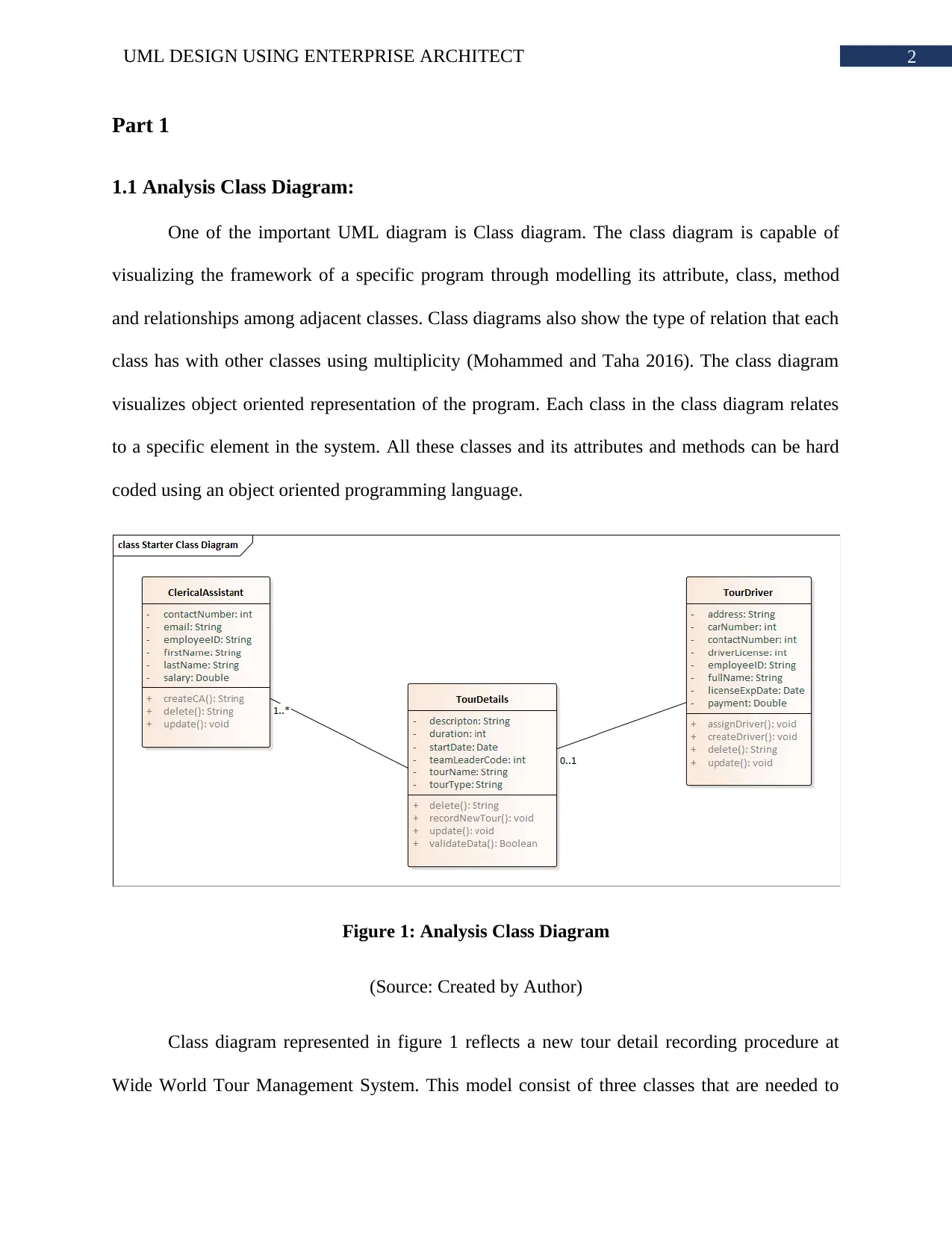
Figure 1: Analysis Class Diagram
(Source: Created by Author)
Class diagram represented in figure 1 reflects a new tour detail recording procedure at
Wide World Tour Management System. This model consist of three classes that are needed to
⊘ This is a preview!⊘
Do you want full access?
Subscribe today to unlock all pages.

Trusted by 1+ million students worldwide
3UML DESIGN USING ENTERPRISE ARCHITECT
represent the basic framework of the application that will handle recording new tour. Each of the
classes has their attributes and operations. The clerical assistant class represent the role of
clerical assistant. createCA operation in this class allows creating a new instance of clerical
assistant. In order to create a new clerical assistant, all the attributes should be provided with a
valid data. employeeID is the unique valued attribute which can be used to search for a clerical
assistant uniquely. For each delete operation in all the three classes, a String value will be
returned. For clerical assistant and driver, this string represent the employeeID and for tour class
it represent tour name.
1.2 Communication Diagram:
Communication diagram, is also known as collaboration diagram, comes under the UML
category called interaction diagram which visualizes communication between the objects like a
sequence diagram but the primary concentration is associations among the application objects
(Rhmann and Saxena 2016). In communication models, the objects are visualized with link
among the objects. Each association has its message with an arrow that represent direction of the
message. This means that each message is passed from one object to another in a sequential
manner. The sequential message flow among the objects are visualized using numbers (XIA et
al. 2018). Communication diagram has actors, objects, associations and messages.
Paraphrase This Document
Need a fresh take? Get an instant paraphrase of this document with our AI Paraphraser
4UML DESIGN USING ENTERPRISE ARCHITECT
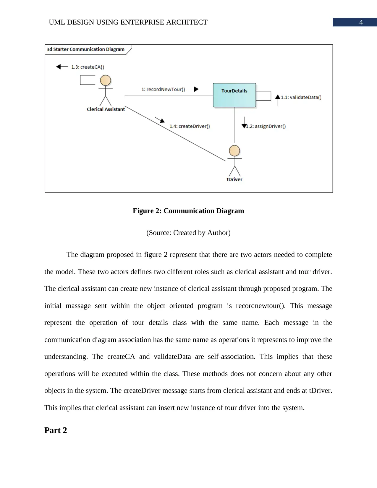
Figure 2: Communication Diagram
(Source: Created by Author)
The diagram proposed in figure 2 represent that there are two actors needed to complete
the model. These two actors defines two different roles such as clerical assistant and tour driver.
The clerical assistant can create new instance of clerical assistant through proposed program. The
initial massage sent within the object oriented program is recordnewtour(). This message
represent the operation of tour details class with the same name. Each message in the
communication diagram association has the same name as operations it represents to improve the
understanding. The createCA and validateData are self-association. This implies that these
operations will be executed within the class. These methods does not concern about any other
objects in the system. The createDriver message starts from clerical assistant and ends at tDriver.
This implies that clerical assistant can insert new instance of tour driver into the system.
Part 2

5UML DESIGN USING ENTERPRISE ARCHITECT
2.1 Sequence Diagram:
In order to model the logic flow within the system, the UML sequence diagram can be a
very good option. The sequence diagram supports both validating as well as documenting logic
of the application (Burgueno, Gogolla and Vallecillo 2017). These logics are generally used for
both the design and analysis of the system. Sequence diagram visualizes dynamic behavior of
proposed application. This UML model has actors, objects, lifelines and messages. There are
also ways to show conditions and loops in the sequence diagram. There are two types of
sequence diagrams such as system level and service level (Minhas et al. 2018). The system level
sequence diagram shows how the actors interacts with the system objects.
⊘ This is a preview!⊘
Do you want full access?
Subscribe today to unlock all pages.

Trusted by 1+ million students worldwide
6UML DESIGN USING ENTERPRISE ARCHITECT
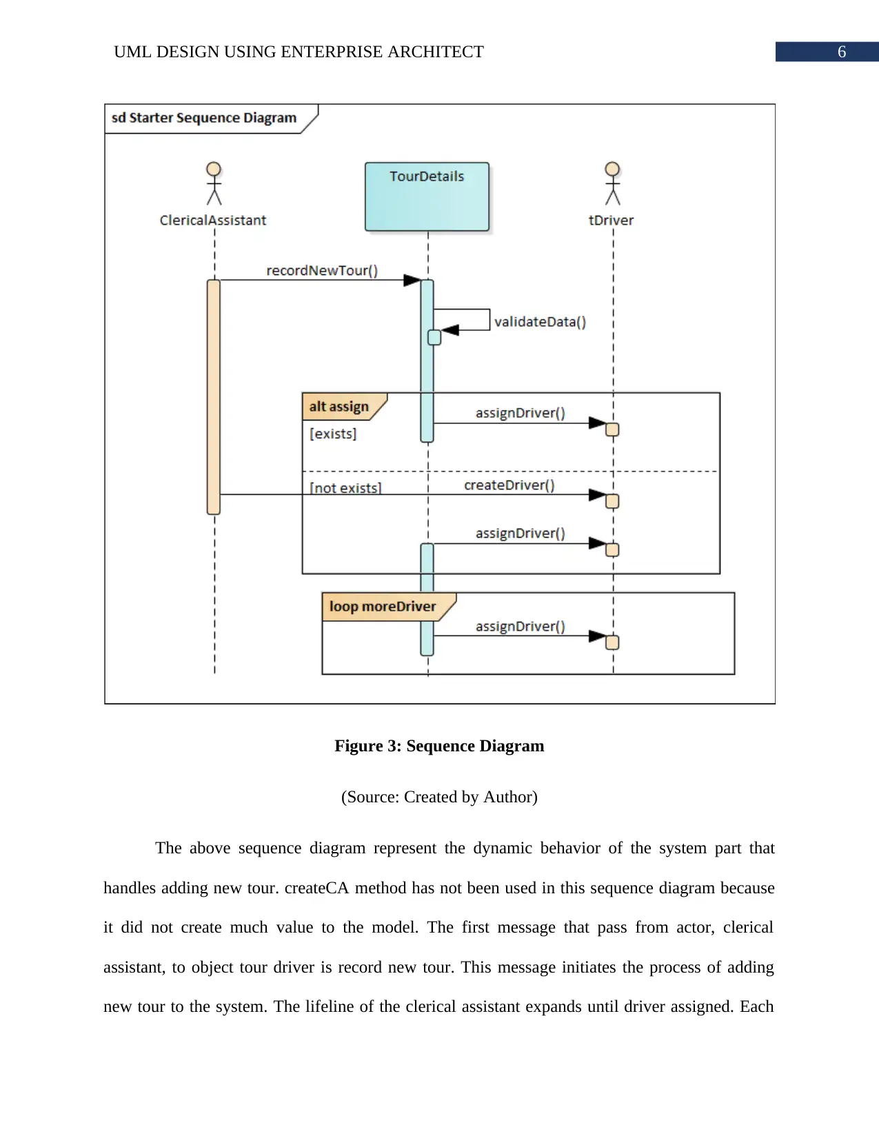
Figure 3: Sequence Diagram
(Source: Created by Author)
The above sequence diagram represent the dynamic behavior of the system part that
handles adding new tour. createCA method has not been used in this sequence diagram because
it did not create much value to the model. The first message that pass from actor, clerical
assistant, to object tour driver is record new tour. This message initiates the process of adding
new tour to the system. The lifeline of the clerical assistant expands until driver assigned. Each
Paraphrase This Document
Need a fresh take? Get an instant paraphrase of this document with our AI Paraphraser
7UML DESIGN USING ENTERPRISE ARCHITECT
record new tour operation, the system needs to validate the entered data. This is important for
ensuring no malicious or error data is entered into the system. The validate data operation is a
self-message that ensures no other object can access this method. As each driver is assigned to
tour, the assign driver message starts from tour object and ends at tDriver actor.
Part 3
3.1 Evaluation:
CASE or Computer-aided software engineering is considered as a broad collection of
effort-saving tools utilized in different phases of software development. These tools are used for
creating frameworks in order to manage projects. These tools are independent for helping users
to remain organized as well as enhance the software quality (Udjaja 2018). CASE tools or
integrated CASE covers whole software development lifecycle process. The application of the
CASE tool is common in system requirement analysis, designing and coding. These tools are
used as integrated elements of a software project for maintenance, modelling, error checking,
diagram generating, designing and evaluation of system. CASE tool also assist the project team
to quickly generate prototypes that are tested by the end users (Kardas and Gomez-Sanz 2017).
Quick end product delivery with high quality is an important role of CASE tool. Within a CASE
repository, everything is centralized into the CASE. CASE tool offers an integrated system
regarding project management information.
There seven types of CASE tools available for use in SDLC phases. The first tool is
diagramming tool. It enables system process, data and control structures in order to be visualized
graphically. Report generators is a secial type of CASE tool that allows the analyst to prototype
the system interface and user experience. It allows the system analyst for identifying data
8UML DESIGN USING ENTERPRISE ARCHITECT
requirements and association. Analyzing tools is used by system analysts for checking the
significance, inconsistency or error specifications within the diagrams, reports and forms. Central
repository CASE tool enables the unified storage of terms, models, reports and information of
project (Katkar et al. 2017). Documentation generator is a CASE tool that allows the analyst to
generate user and technical documentation within standard form. Code generator case tool is
used by the coders to generate code for system. System designers uses the diagramming tool for
generating diagrams with accuracy. The CASE tool allows the system analyst and designers to
generate requirements and design diagrams with accurate data based on the proposed system
(Kardas and Gomez-Sanz 2017). The system will be providing automated quality and error
checking facility to make the end results with optimum quality.
In order to design the class diagram, communication diagram and sequence diagram of
record new tour, it was essential to maintain same flow between all these diagrams. The logic
behind all these three diagrams must be same. The constraints and conditions were needed to be
maintained all these three diagrams (Udjaja 2018). CASE tools provided the environment where
the logic and errors of the diagrams cloud be analyzed. The attributes, messages, operations,
actors, objects and relationships should have been as per the record new tour requirements.
CASE tool also helped in gathering and analyzing these requirements based on which diagrams
are designed. The documentation of the diagrams are also important to share the information that
understates the logic behind these (Katkar et al. 2017). CASE tool was a complete package that
helped in defining the constraints, logic, conditions and results of the record new tour
application.
Enterprise Architect is an integrated modelling platform that comes under the category of
diagramming CASE tool. This supports the entire life cycle modelling for software applications.
⊘ This is a preview!⊘
Do you want full access?
Subscribe today to unlock all pages.

Trusted by 1+ million students worldwide
9UML DESIGN USING ENTERPRISE ARCHITECT
It helps in constructing the easy to maintain and robust systems. The Enterprise Architect
provides a built in requirement handling mechanism, maintaining high level specifications,
designing the system, testing of UML models and many more. The Enterprise Architect has a
great graphical interface that is easy to use and extremely dynamic (Kosa and Karakus 2018).
The interface learnability may be not easy as tools like visio or draw.io but the dynamic features
of Enterprise Architect is much better for production level modelling. Enterprise Architect can
load big models in less time than common modelling applications. This CASE tools features a
high-performance repository model. The models developed in Enterprise Architect can be
brought to life using the inbuilt simulation feature. The designers and analyst can also control the
simulations.
Paraphrase This Document
Need a fresh take? Get an instant paraphrase of this document with our AI Paraphraser
10UML DESIGN USING ENTERPRISE ARCHITECT
Bibliography:
Burgueno, L., Gogolla, M. and Vallecillo, A., 2017. Teaching model views with UML and OCL.
Kardas, G. and Gomez-Sanz, J.J., 2017. Special issue on model-driven engineering of multi-
agent systems in theory and practice. Computer Languages, Systems & Structures, 50, pp.140-
141.
Katkar, M.N.Y., Kulkarni, R.S., Patil, P.A., Katkar, M.S.E., Katkar, M.N.Y., Kulkarni, R.S.,
Patil, P.A. and Katkar, M.S.E., 2017. A Review on Design and Annalysis of Gate Valve using
Various Computer Aided Techniques. International Journal, 3, pp.218-220.
Kosa, T. and Karakus, F., 2018. The effects of computer-aided design software on engineering
students’ spatial visualisation skills. European Journal of Engineering Education, 43(2), pp.296-
308.
Minhas, N.M., Masood, S., Petersen, K. and Nadeem, A., 2018. A Systematic Mapping of Test
Case Generation Techniques Using UML Interaction Diagram. Journal of Software: Evolution
and Process.
Mohammed, O.S. and Taha, D.B., 2016. Conducting multi-class security metrics from Enterprise
Architect class diagram. International Journal of Computer Science and Information Security,
14(4), p.56.
Rhmann, W. and Saxena, V., 2016. Generation of test cases from uml sequence diagram based
on extenics theory. British Journal of Mathematics & Computer Science, 16(1).
11UML DESIGN USING ENTERPRISE ARCHITECT
Udjaja, Y., 2018. Ekspanpixel Bladsy Stranica: Performance Efficiency Improvement of Making
Front-End Website Using Computer Aided Software Engineering Tool. Procedia Computer
Science, 135, pp.292-301.
XIA, C.S., Hui, Y.A.N., Yue, W.A.N.G. and Ling, S.H.I., 2018. Modeling and Analysis of the
Support System of Space-based Anti-missile Information Based on UML. DEStech Transactions
on Computer Science and Engineering, (mso).
⊘ This is a preview!⊘
Do you want full access?
Subscribe today to unlock all pages.

Trusted by 1+ million students worldwide
1 out of 12
Related Documents
Your All-in-One AI-Powered Toolkit for Academic Success.
+13062052269
info@desklib.com
Available 24*7 on WhatsApp / Email
![[object Object]](/_next/static/media/star-bottom.7253800d.svg)
Unlock your academic potential
Copyright © 2020–2025 A2Z Services. All Rights Reserved. Developed and managed by ZUCOL.


