Network Diagram for International Plastics
VerifiedAdded on 2023/03/31
|14
|1534
|482
AI Summary
This document provides an analysis of the international plastics network diagram and offers recommendations for IT infrastructure improvements. It discusses the decisions made in the diagram, current network risks, and suggestions for mitigating the risks and improving the network.
Contribute Materials
Your contribution can guide someone’s learning journey. Share your
documents today.
University
Semester
Network Diagram
Student ID
Student Name
Submission Date
1
Semester
Network Diagram
Student ID
Student Name
Submission Date
1
Secure Best Marks with AI Grader
Need help grading? Try our AI Grader for instant feedback on your assignments.

Table of Contents
Project Description................................................................................................................................3
Network Diagram..................................................................................................................................3
1. Location 1 – China Headquarters...............................................................................................3
1.1 Decisions...........................................................................................................................4
1.2 Risk Summary...................................................................................................................5
1.3 Risk Mitigation..................................................................................................................5
1.4 Recommended Improvements............................................................................................5
1.5 Proposed Network Infrastructure.......................................................................................5
2. Location 2 - Corporate Headquarters.........................................................................................5
2.1 Decisions...........................................................................................................................6
2.2 Risk Summary...................................................................................................................7
2.3 Risk Mitigation..................................................................................................................7
2.4 Recommended Improvements............................................................................................7
2.5 Proposed Network Infrastructure.......................................................................................7
3. Location 3 – Pontiac..................................................................................................................7
3.1 Decisions...........................................................................................................................8
3.2 Risk Summary...................................................................................................................8
3.3 Risk Mitigation..................................................................................................................8
3.4 Recommended Improvements............................................................................................8
3.5 Proposed Network Infrastructure.......................................................................................8
4. Location 4 – Albany..................................................................................................................8
4.1 Decisions...........................................................................................................................9
4.2 Risk Summary...................................................................................................................9
4.3 Risk Mitigation..................................................................................................................9
4.4 Recommended Improvements............................................................................................9
4.5 Proposed Network Infrastructure.......................................................................................9
2
Project Description
Main objective of this project is used to analyse the international plastics network
diagram to update the each of the four locations international plastics diagrams with
recommendations for IT infrastructure improvements by using the Microsoft Visio. And, also
explain the decision on the diagram, current network risks and provide the recommendations
for mitigating the risks and improvements for the networks. These are will be discussed and
analysed in detail.
Network Diagram
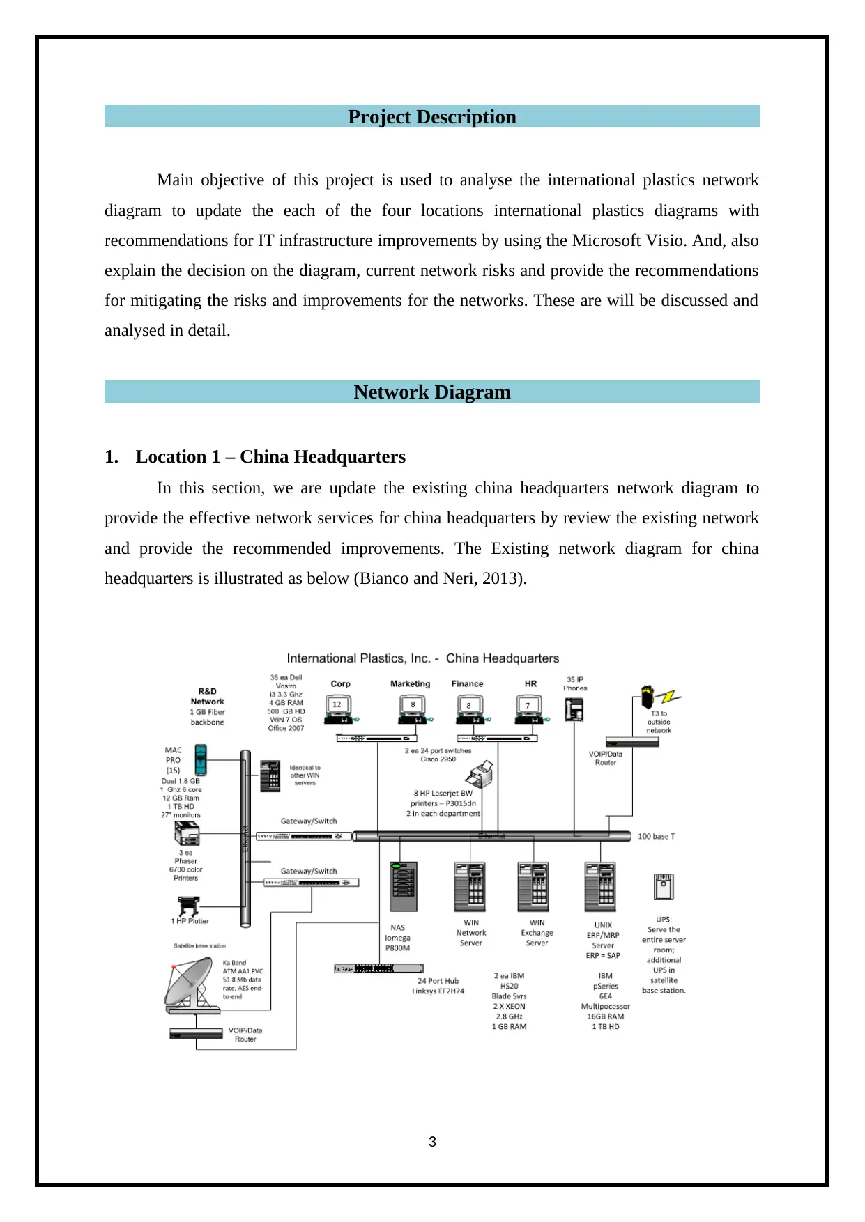
1. Location 1 – China Headquarters
In this section, we are update the existing china headquarters network diagram to
provide the effective network services for china headquarters by review the existing network
and provide the recommended improvements. The Existing network diagram for china
headquarters is illustrated as below (Bianco and Neri, 2013).
3
Main objective of this project is used to analyse the international plastics network
diagram to update the each of the four locations international plastics diagrams with
recommendations for IT infrastructure improvements by using the Microsoft Visio. And, also
explain the decision on the diagram, current network risks and provide the recommendations
for mitigating the risks and improvements for the networks. These are will be discussed and
analysed in detail.
Network Diagram
1. Location 1 – China Headquarters
In this section, we are update the existing china headquarters network diagram to
provide the effective network services for china headquarters by review the existing network
and provide the recommended improvements. The Existing network diagram for china
headquarters is illustrated as below (Bianco and Neri, 2013).
3
1.1 Decisions
The existing network diagram for china headquarters is uses the,
Gateway Switches
VoIP/Data Routers
24 port Hub - Linksys
IBM P series Multi processor
100 base T Ethernet standard
Exchange server
Network Server and More
Based on existing network, the Ethernet is used to connects the all the devices on the
network. This network uses the 100 base T Ethernet which is used to provide the 10 Mbps
data rate and maximum distance is 100 meters. So proposed network diagram, we are use the
10GBase-LX4 which is used to provide the 10 Gbps data rate and maximum distance is 300
meters and it is used to provide the effective network services for corporate headquarters and
it also provide the flexible and stable network.
1.2 Risk Summary
The existing network diagram for china headquarters is use the T3 connection firewall
and it does not use the Cisco firewall. So, it does not provide the expected security for
network infrastructure connections for an organization.
1.3 Risk Mitigation
To mitigate the risk by replace the T3 connection to Cisco firewall for proposed
network diagram which is used to provide the effective security for a china headquarters
network.
1.4 Recommended Improvements
In proposed network, we needs to updates the Ethernet routers as 10GBase-LX4,
Ethernet switch and /hub as Cisco 48 port hub and also use Cisco firewall. These are used to
provide the effective network and stable network for a china headquarters. These are also
increases the switches speeds and provide the following features such as,
Availability
Scalability
High security
4
Secure Best Marks with AI Grader
Need help grading? Try our AI Grader for instant feedback on your assignments.
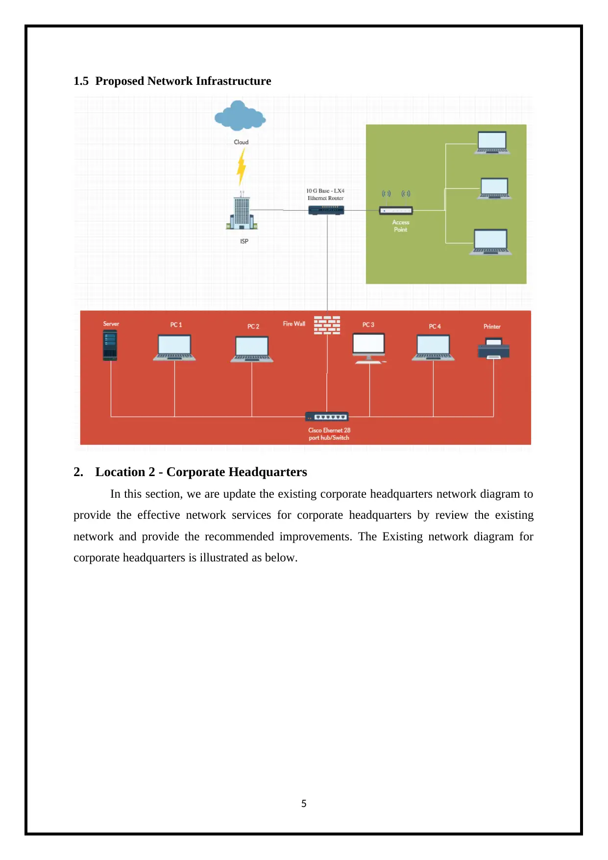
1.5 Proposed Network Infrastructure
2. Location 2 - Corporate Headquarters
In this section, we are update the existing corporate headquarters network diagram to
provide the effective network services for corporate headquarters by review the existing
network and provide the recommended improvements. The Existing network diagram for
corporate headquarters is illustrated as below.
5
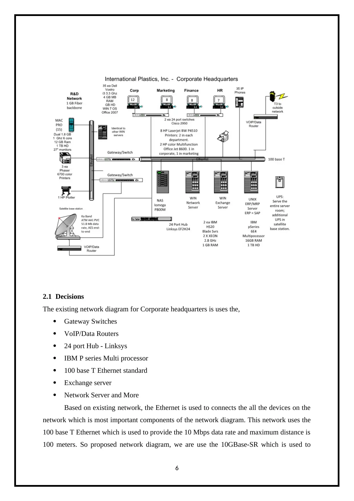
2.1 Decisions
The existing network diagram for Corporate headquarters is uses the,
Gateway Switches
VoIP/Data Routers
24 port Hub - Linksys
IBM P series Multi processor
100 base T Ethernet standard
Exchange server
Network Server and More
Based on existing network, the Ethernet is used to connects the all the devices on the
network which is most important components of the network diagram. This network uses the
100 base T Ethernet which is used to provide the 10 Mbps data rate and maximum distance is
100 meters. So proposed network diagram, we are use the 10GBase-SR which is used to
6
provide the 10 Gbps data rate and maximum distance is 300 meters and it is used to provide
the effective network services for corporate headquarters and it also provide the flexible and
stable network.
2.2 Risk Summary
The existing network diagram for corporate headquarters is use the T3 connection
firewall and it does not use the Cisco firewall. So, it does not provide the expected security
for network infrastructure connections for an organization.
2.3 Risk Mitigation
To mitigate the risk by use the Cisco firewall for proposed network diagram which is
used to provide the effective security for a corporate headquarters network.
2.4 Recommended Improvements
In proposed network, we needs to updates the Ethernet routers as 10GBase-SR,
Ethernet switch and /hub as Cisco 28 port hub and also use Cisco firewall. These are used to
provide the effective network and stable network for a corporate headquarters. These are also
increases the switches speeds and provide the following features such as (Hallberg, 2013),
Highest network availability
Scalability
High security
Optimizing the IPv4 and IPv6 multicast traffic in the LAN
Avoid TCP congestion
7
Paraphrase This Document
Need a fresh take? Get an instant paraphrase of this document with our AI Paraphraser

2.5 Proposed Network Infrastructure
3. Location 3 – Pontiac
In this section, we are update the existing Pontiac network diagram to provide the
effective network services for Pontiac by review the existing network and provide the
recommended improvements. The Existing network diagram for Pontiac is illustrated as
below.
8
3. Location 3 – Pontiac
In this section, we are update the existing Pontiac network diagram to provide the
effective network services for Pontiac by review the existing network and provide the
recommended improvements. The Existing network diagram for Pontiac is illustrated as
below.
8
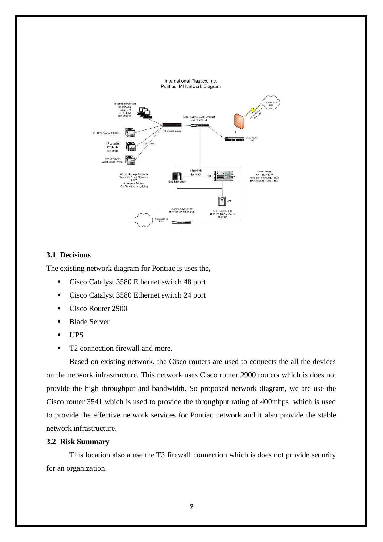
3.1 Decisions
The existing network diagram for Pontiac is uses the,
Cisco Catalyst 3580 Ethernet switch 48 port
Cisco Catalyst 3580 Ethernet switch 24 port
Cisco Router 2900
Blade Server
UPS
T2 connection firewall and more.
Based on existing network, the Cisco routers are used to connects the all the devices
on the network infrastructure. This network uses Cisco router 2900 routers which is does not
provide the high throughput and bandwidth. So proposed network diagram, we are use the
Cisco router 3541 which is used to provide the throughput rating of 400mbps which is used
to provide the effective network services for Pontiac network and it also provide the stable
network infrastructure.
3.2 Risk Summary
This location also a use the T3 firewall connection which is does not provide security
for an organization.
9
3.3 Risk Mitigation
To mitigate the risk by choose the Cisco firewall which is used to provide the
effective security for an organization.
3.4 Recommended Improvements
In proposed network, we needs to updates the Ethernet routers as Cisco router 3541,
Cisco switch as Cisco Catalyst 9200 Ethernet switch 48 ports and Cisco Catalyst 9200
Ethernet switch 24 ports and also use Cisco firewall. These are used to provide the effective
network and stable network for a Pontiac location. These are also increases the switches
speeds and provide the following features such as (Wallace, 2006),
Scalability
High security
Optimizing the IPv4 and IPv6 multicast traffic in the LAN
Avoid TCP congestion
Network Availability
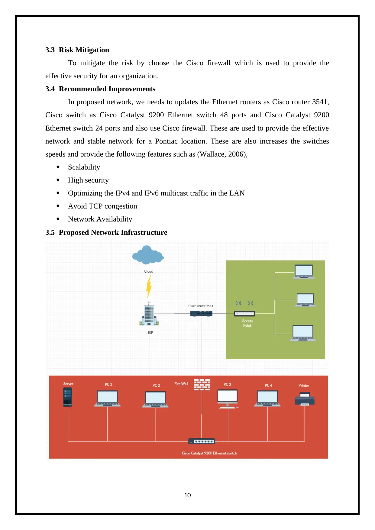
3.5 Proposed Network Infrastructure
10
To mitigate the risk by choose the Cisco firewall which is used to provide the
effective security for an organization.
3.4 Recommended Improvements
In proposed network, we needs to updates the Ethernet routers as Cisco router 3541,
Cisco switch as Cisco Catalyst 9200 Ethernet switch 48 ports and Cisco Catalyst 9200
Ethernet switch 24 ports and also use Cisco firewall. These are used to provide the effective
network and stable network for a Pontiac location. These are also increases the switches
speeds and provide the following features such as (Wallace, 2006),
Scalability
High security
Optimizing the IPv4 and IPv6 multicast traffic in the LAN
Avoid TCP congestion
Network Availability
3.5 Proposed Network Infrastructure
10
Secure Best Marks with AI Grader
Need help grading? Try our AI Grader for instant feedback on your assignments.
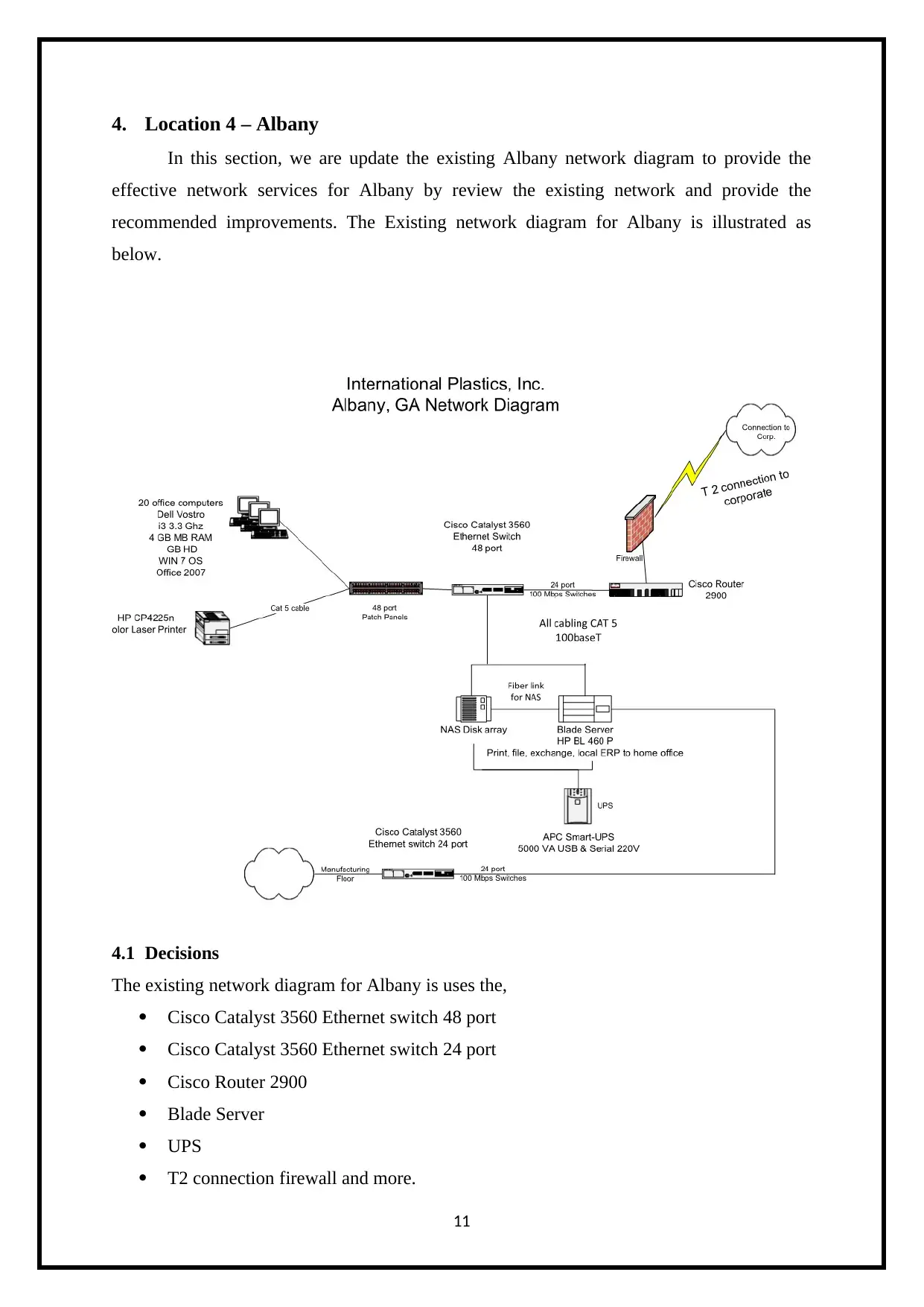
4. Location 4 – Albany
In this section, we are update the existing Albany network diagram to provide the
effective network services for Albany by review the existing network and provide the
recommended improvements. The Existing network diagram for Albany is illustrated as
below.
4.1 Decisions
The existing network diagram for Albany is uses the,
Cisco Catalyst 3560 Ethernet switch 48 port
Cisco Catalyst 3560 Ethernet switch 24 port
Cisco Router 2900
Blade Server
UPS
T2 connection firewall and more.
11
Based on existing network, the Cisco routers are used to connects the all the devices
on the network infrastructure. This network uses Cisco router 2900 routers which is does not
provide the high throughput and bandwidth. So proposed network diagram, we are use the
Cisco router 3541 which is used to provide the throughput rating of 400mbps which is used
to provide the effective network services for Pontiac network and it also provide the stable
network infrastructure. And, use the all devices are wireless network because it is used to
provide the reliable network.
4.2 Risk Summary
This network uses the wired network connect which is does not provide the reliable
network connection and also it uses the T3 firewall connection which is does not provide the
high security for an organization.
4.3 Risk Mitigation
To resolve the identifies risk on the network by uses the wireless network connections
and Cisco firewall connection both are used to provide the high reliable and security of the
network infrastructures.
4.4 Recommended Improvements
In proposed network, we needs to updates the Ethernet routers as Cisco router 4351,
Cisco switch as Cisco Catalyst 9200 Ethernet switch 48 ports and Cisco Catalyst 9200
Ethernet switch 24 ports and also use Cisco firewall. These are used to provide the effective
network and stable network for an Albany location. These are also increases the switches
speeds and provide the following features such as,
Reliability
High security
Avoid TCP congestion
Network Availability
12
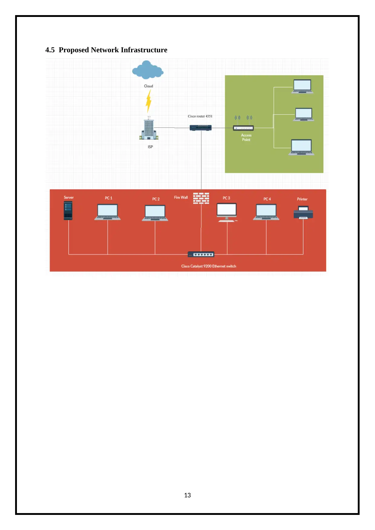
4.5 Proposed Network Infrastructure
13
13
Paraphrase This Document
Need a fresh take? Get an instant paraphrase of this document with our AI Paraphraser

References
Bianco, A. and Neri, F. (2013). Next Generation Optical Network Design and Modelling.
New York, NY: Springer.
Hallberg, B. (2013). Networking. New York: McGraw-Hill Publishing.
Wallace, K. (2006). Voice over IP first-step. Indianapolis: Cisco Press.
14
Bianco, A. and Neri, F. (2013). Next Generation Optical Network Design and Modelling.
New York, NY: Springer.
Hallberg, B. (2013). Networking. New York: McGraw-Hill Publishing.
Wallace, K. (2006). Voice over IP first-step. Indianapolis: Cisco Press.
14
1 out of 14
Related Documents


Your All-in-One AI-Powered Toolkit for Academic Success.
+13062052269
info@desklib.com
Available 24*7 on WhatsApp / Email
![[object Object]](/_next/static/media/star-bottom.7253800d.svg)
Unlock your academic potential
© 2024 | Zucol Services PVT LTD | All rights reserved.