Development of Quadcopter with Camera for Accident Response System
VerifiedAdded on 2023/04/21
|56
|12253
|131
Project
AI Summary
This document presents a final year project focusing on the design, implementation, and application of a quadcopter equipped with a camera for accident support. The quadcopter utilizes an Arduino board and onboard sensors to aid in emergency response scenarios, such as fire accidents, by locating individuals inside buildings and facilitating evacuation. The system includes live camera feed transmission to the Emergency Response Team (ERT) for efficient evacuation planning. The project covers aspects such as autonomous control, hardware components (including Arduino, sensors, motors, and communication modules), calculations for flight principles, circuit diagrams, and experimental results. The research aims to provide a cost-effective and efficient solution for improving safety and response times in emergency situations, highlighting the potential of quadcopters in critical applications.
University
*** Semester
A Final Year Project
on
Quadcopter with Camera
Student Name:
Register Number:
Submission Date:
*** Semester
A Final Year Project
on
Quadcopter with Camera
Student Name:
Register Number:
Submission Date:
Paraphrase This Document
Need a fresh take? Get an instant paraphrase of this document with our AI Paraphraser
Abstract
The spotlight of this research is on quadcopter to support the accidents. The research ensures to
review and examine the difficulties faced during the accidents to provide security. This research
covers the design, implementation and application of quadcopter that can be used in accidents
like fire, to find the people inside the building with the help of a special camera and send sound
to then to safe place to evacuate point. Consequently, the camera is live for the (ERT) emergency
respond team to complete the fast evacuation plan and stop the fire. The task includes
accomplishing autonomous control of the quadcopter which is an unmanned Air Vehicle. It is a
small 4 rotor helicopter, which takes the help of an onboard smart phone as well as the Arduino
board containing air quality sensors. Subsequently, the safety aspects are reviewed in this
research. In this technology oriented world, the technology advancement is equivalent to the
growth of the automobiles which creates traffic jam and this in turn results in sound pollution
and air pollution. Therefore, there is needed to look for other alternative like airways instead of
roadways to reach the emergency spots on time. Because, reaching the spot on time is crucial to
save lives of the victims.
Keywords: Arduino; microcontrollerATMEGA328; Accelerometer; BLDC Motor; Flight
controller Board; Transmitter; Receiver; Propellers; Electronic speed controller.
Table of Contents
Chapter: 1........................................................................................................................................................................ 1
1.1 Introduction........................................................................................................................................................ 1
1.2 Research Objectives............................................................................................................................................ 2
1.3 Research Scope................................................................................................................................................... 2
1.4 Research Content................................................................................................................................................ 3
1.5 Dissertation Overview......................................................................................................................................... 3
Chapter: 2........................................................................................................................................................................ 4
2.1 Literature Review............................................................................................................................................... 4
2.2 Component....................................................................................................................................................... 13
Chapter: 3...................................................................................................................................................................... 21
3.1 Calculations of flying principle using x type of quadcopter (4 motors)...............................................................21
3.2 Circuit Diagram................................................................................................................................................ 27
Chapter:4....................................................................................................................................................................... 28
4.1 Discussion and Observation of results................................................................................................................28
Chapter: 5...................................................................................................................................................................... 35
5.1 Conclusion........................................................................................................................................................ 35
5.2 Future Work..................................................................................................................................................... 37
5.3 Recommendations............................................................................................................................................. 38
Chapter 6....................................................................................................................................................................... 39
6.1 References......................................................................................................................................................... 39
6.2 Appendix.......................................................................................................................................................... 42
List of Figures
Figure 1 Arduino.............................................................................................................................................................. 5
Figure 2 Range sensor used in our quadcopter.............................................................................................................5
Figure 3 IMU used in our quadcopter.............................................................................................................................6
Figure 4 Hardware description of Quadcopter...............................................................................................................7
Figure 5 Yaw, Pitch & Roll rotation.................................................................................................................................. 8
Figure 6 RC Emulation scheme..................................................................................................................................... 9
Figure 7 Early prototype with GPS module under the support panel............................................................................10
Figure 8 Fused Description Modeling........................................................................................................................... 11
Figure 9 Body frame printing using 3D printer..............................................................................................................12
Figure 10: Remote controller model is FS-ia6...............................................................................................................14
Figure 11: Arduino Due Board....................................................................................................................................... 15
Figure 12: Gyroscope model MPU-6050 (Gy-521)........................................................................................................16
Figure 13: HC-05 Bluetooth Module..............................................................................................................................17
Figure 14: Quadcopter Motors...................................................................................................................................... 17
Figure 15: Propellers..................................................................................................................................................... 18
⊘ This is a preview!⊘
Do you want full access?
Subscribe today to unlock all pages.

Trusted by 1+ million students worldwide
Figure 16: Electronics Speed Controller........................................................................................................................19
Figure 17: Battery Li - Po.............................................................................................................................................. 20
Figure 18: HC-SR04 Ultrasonic Sensors....................................................................................................................... 21
Figure 19: Block Diagram.............................................................................................................................................. 29
Figure 20: Circuit Diagram............................................................................................................................................ 29
Figure 21: Quadcopter Motor Direction.........................................................................................................................31
Figure 22: Server code & output................................................................................................................................... 33
Figure 23: Client code & output..................................................................................................................................... 34
Figure 24: Final design of the Arduino based quadcopter.............................................................................................34
Figure 25: Quadcopter.................................................................................................................................................. 35
Figure 26: Quadcopter along with transmitter...............................................................................................................35
List of Abbreviations
Paraphrase This Document
Need a fresh take? Get an instant paraphrase of this document with our AI Paraphraser
Chapter: 1
1.1 Introduction
A quadcopter refers to a device of assistance that contains high demand in both
mechanical and surveillance field. With the advancement of technology, the standard has
improved with several benefiting features along with exceptionally fascinating employments of
Quadcopter technology has advanced remarkably. The following study incorporates the structure
as well as the advancement of the Quadcopter by utilizing the ATMEGA328. Such a framework
will either utilize the GPS system or it might utilize the camera to have a recognizable proof.
This framework could be controlled with the help of a remote system or by using the transmitter
within the convenience of an individual. This idea encourages the activities of surveillance. The
quadcopter is highly beneficial and hence this research ensures to find its importance with a
camera, by using Arduino.
Quadcopter is mainly denoted as a flying unit, which is utilized for lifting the objects
starting from one point to the other point, in just less time or it could be utilized for the purpose
of surveillance. For the industry level applications, the quadcopter is developed with the help of
KK board module, where it accompanies the pre-modified KK board as well as the balanced
gyroscope module that isn't economical for the applications that are low-level. It is the
financially savvy strategy. This work is proposed for making the quadcopter economical as well
as proficient for the applications that fall under low-level i.e., which has designed and developed
the quadcopter by utilizing the Arduino Uno board rather than the KK flight Controller boardthat
is pre-customized, as it contains a large number of applications such as quadcopter mounted with
both camera as well as the GPS tracker, which can be utilized for the surveillance of wide
territories. For example, coast guard applications, forests and so on.
The conventional helicopter with a fundamental rotor and a tail rotor forces numerous
indistinguishable properties from a quadcopter. In any case, the quadcopter has no moving parts
aside from the turning engines as well as the propellers, whereas the conventional helicopter
requires mind-boggling hub for making it conceivable so that the engine hub can be turned, to
instigate an interpreting development. The quadcopter is likewise less inclined to vibrations,
what's more, it is increasingly adaptable with regards to the position of the focal point of gravity.
Because of the rotors’ small size, they all can be more effortlessly secured, which makes it more
secure to fly inside.
1
This research is mainly on the quadcopter, to support the spots of accidents. The research
ensures to review and examine the difficulties faced during the accidents to provide security.
This research covers the design, implementation and application of quadcopter that can be used
in accidents like fire, to find the people inside the building with the help of a special camera and
send sound to then to safe place to evacuate point. Consequently, the camera is live for the (ERT)
Emergency Respond Team to complete the fast evacuation plan and stop the fire. Here, the task
includes autonomous control of the quadcopter which is an unmanned Air Vehicle. It is a small 4
rotor helicopter, which takes the help of an Android smart phone as well as the Arduino board
containing air quality sensors. Subsequently, the safety aspects will be reviewed in this research.
In this technology oriented world, the technology advancement is equivalent to the growth of the
automobiles which creates traffic jam and this in turn results in sound pollution and air pollution.
Therefore, there is need to look for other alternative like airways instead of roadways to reach
the emergency spots on time. Because, reaching the spot on time is crucial to save the lives of the
victims.
Furthermore, the task of designing the autonomous quadcopter is complicated. Here, for
tackling the tasks that are large the strategy of divides and conquers is used. This research can
decrease all the complexities by dividing the tasks into smaller independent tasks.
1.2 Research Objectives
The research objectives of this research include designing and implementing the
Quadcopter with the camera by utilizing the Arduino. This report will discuss and explain about
a quadcopter that can be used in accidents such as fire to find the people inside building using
special camera and send sound to then to safe place to evacuate point. At the same time, the
camera is live to (ERT) Emergency respond team to do a fast evacuation plan and stop the fire.
1.3 Research Scope
This research study’s scope includes to design and implement the Quadcopter with
camera using Arduino. The quadcopter can be utilized to help in the critical situations like fire
accidents to provide security measures. The main scope of the quadcopter is that it is utilized to
take airborne photography, for security, for advanced investigation and offers much more
features. This project’s results will help individuals in the disasters and tragedies by reaching the
2
⊘ This is a preview!⊘
Do you want full access?
Subscribe today to unlock all pages.

Trusted by 1+ million students worldwide
areas where people can't reach instantly for help. Basically, the quadcopter is being utilized for
identification of objects with the help of image processing in country’s boarder security.
Thus, this report’s aim includes designing and implementing the Quadcopter with a
camera by using the Arduino. It requires coding for the hardware. The solution contains Android
Smartphone and also the Arduino board, where the Smartphone is used to manage the navigation.
Moreover, it also takes decisions when the Arduino board contains all the necessary sensors and
takes control of the quadcopter.
1.4 Research Content
The following are the research areas that will be required for this dissertation- For
Designing the quadcopter, for implementation of quadcopter for helping the ERT to accomplish
secure evacuation. Additionally, the Android board, FS-i6 Remote controller model, FS-ia6
receiver model, Arduino board Nano, Gyroscope model MPU-6050 (Gy-521), HC-05 Bluetooth
Module, motors, Propellers, Electronics speed controller, Battery LiPo 5200 mAh, HC-SR04
Ultrasonic Sensors will be covered.
1.5 Dissertation Overview
Chapter 1 includes the introduction of the topic to be covered in the project. It signifies
the objective and scope of the project.
Chapter 2 contains Literature Review and information about the components to be used
in this project. The literature review helps to review various research works of the researchers to
understand the topics being discussed in this report.
Chapter 3 comprises of calculations of flying principle using x type of quadcopter and the
circuit diagrams.
Chapter 4 provides the discussion and result’s observation.
Chapter 5comprises of conclusion as well as the future work. Finally, Chapter 6 includes
the references and appendix.
3
Paraphrase This Document
Need a fresh take? Get an instant paraphrase of this document with our AI Paraphraser
Chapter: 2
2.1 Literature Review
According to (VikaneHystad and Brobakk Lehn, 2015), the prevalence of the quadcopters
has been expanding because the sensors and control frameworks are advancing and are more
affordable. There are numerous business quadcopters accessible available today, yet they are
frequently difficult to design and understand. The time required to get a handle on the current
frameworks could be spent structuring better arrangements. This task expects to utilize justifiable
framework portrayals and the sensor models are utilized as the premise for the structure
configurable estimators and controllers. Further, for manufacturing the quadcopter appropriate
instructive purposes are used, where it also helps in the future control development. The
framework comprises of a few segments for important sensor input and they are-an Arduino
microcontroller, the Windows user interface and the radio transmitter. All sifting of the signals
framework states’ estimation, figuring out the control sources’ information and correspondence
taking care is done on a microcontroller, when the Windows application permits the user to direct
different activities. For accomplishing straight forward replicability, the 3-Dimentional model of
the edge is created by the "Specialists in Team". This furnished the valuable involvement in
undertaking the executives. Palatable mentality gauges were gotten, a steady frame of mind
controller is derived and actualized, a user-controlled Windows application was effectively
created and the quadcopter outline is made with added substance fabricating. On the other hand,
all the mechanical components and sensors utilized for the quadcopter are explored. It is
calculated that the Arduino Leonardo is enough. It was noticed that a board with sufficient
computer power and memory is necessary for computing the extended Kalman filter along with
the optimal control input, when at the same time process input from numerous sensors. It was
also identified that the Arduino Leonardo lacked required SRAM and flash memory, and even
they ran out of pins. Hence, due to this there was a necessity to upgrade the board to be highly
powerful. The development wads eased by upgrading the software.The Arduino Leonardo as
well as Arduino Due are compared.
4
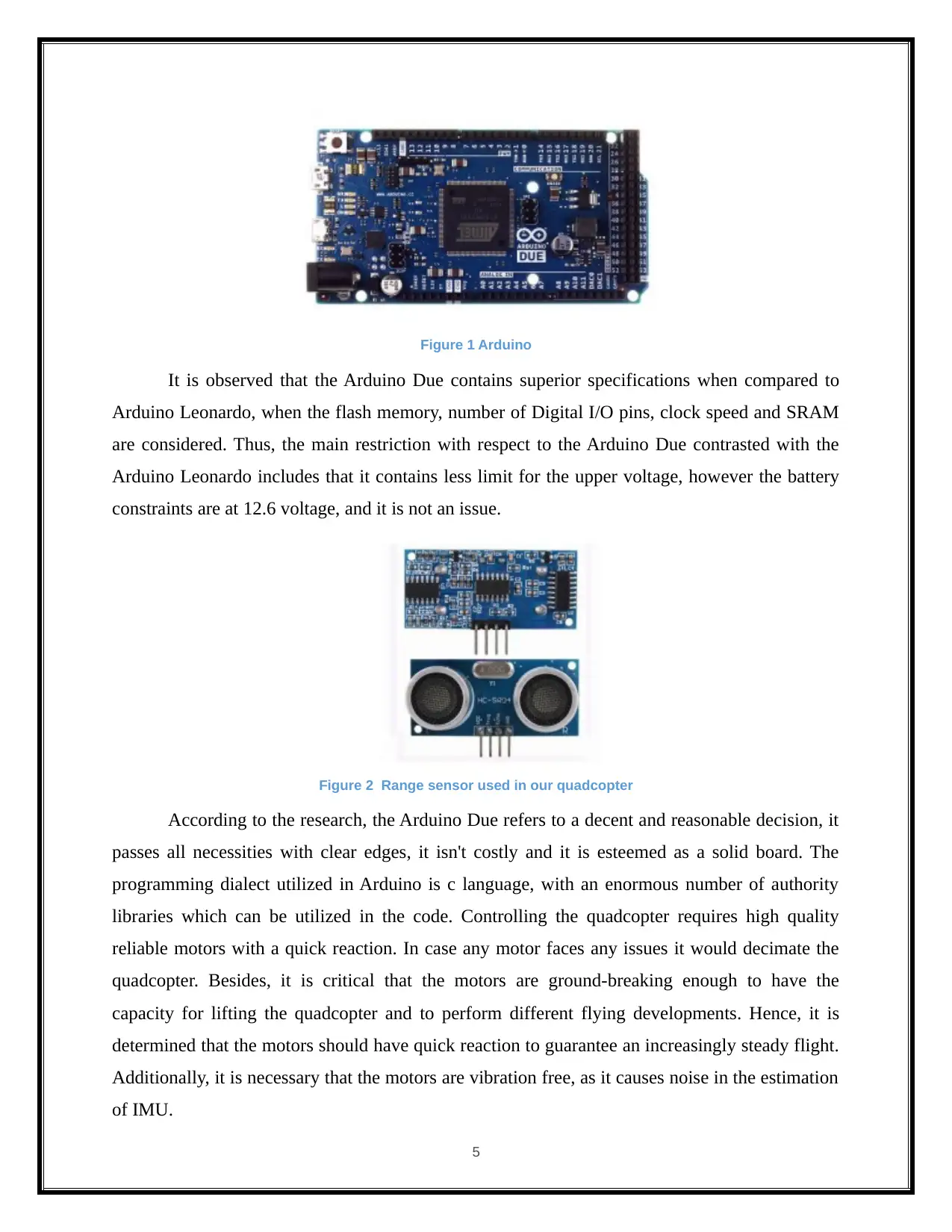
Figure 1 Arduino
It is observed that the Arduino Due contains superior specifications when compared to
Arduino Leonardo, when the flash memory, number of Digital I/O pins, clock speed and SRAM
are considered. Thus, the main restriction with respect to the Arduino Due contrasted with the
Arduino Leonardo includes that it contains less limit for the upper voltage, however the battery
constraints are at 12.6 voltage, and it is not an issue.
Figure 2 Range sensor used in our quadcopter
According to the research, the Arduino Due refers to a decent and reasonable decision, it
passes all necessities with clear edges, it isn't costly and it is esteemed as a solid board. The
programming dialect utilized in Arduino is c language, with an enormous number of authority
libraries which can be utilized in the code. Controlling the quadcopter requires high quality
reliable motors with a quick reaction. In case any motor faces any issues it would decimate the
quadcopter. Besides, it is critical that the motors are ground-breaking enough to have the
capacity for lifting the quadcopter and to perform different flying developments. Hence, it is
determined that the motors should have quick reaction to guarantee an increasingly steady flight.
Additionally, it is necessary that the motors are vibration free, as it causes noise in the estimation
of IMU.
5
⊘ This is a preview!⊘
Do you want full access?
Subscribe today to unlock all pages.

Trusted by 1+ million students worldwide
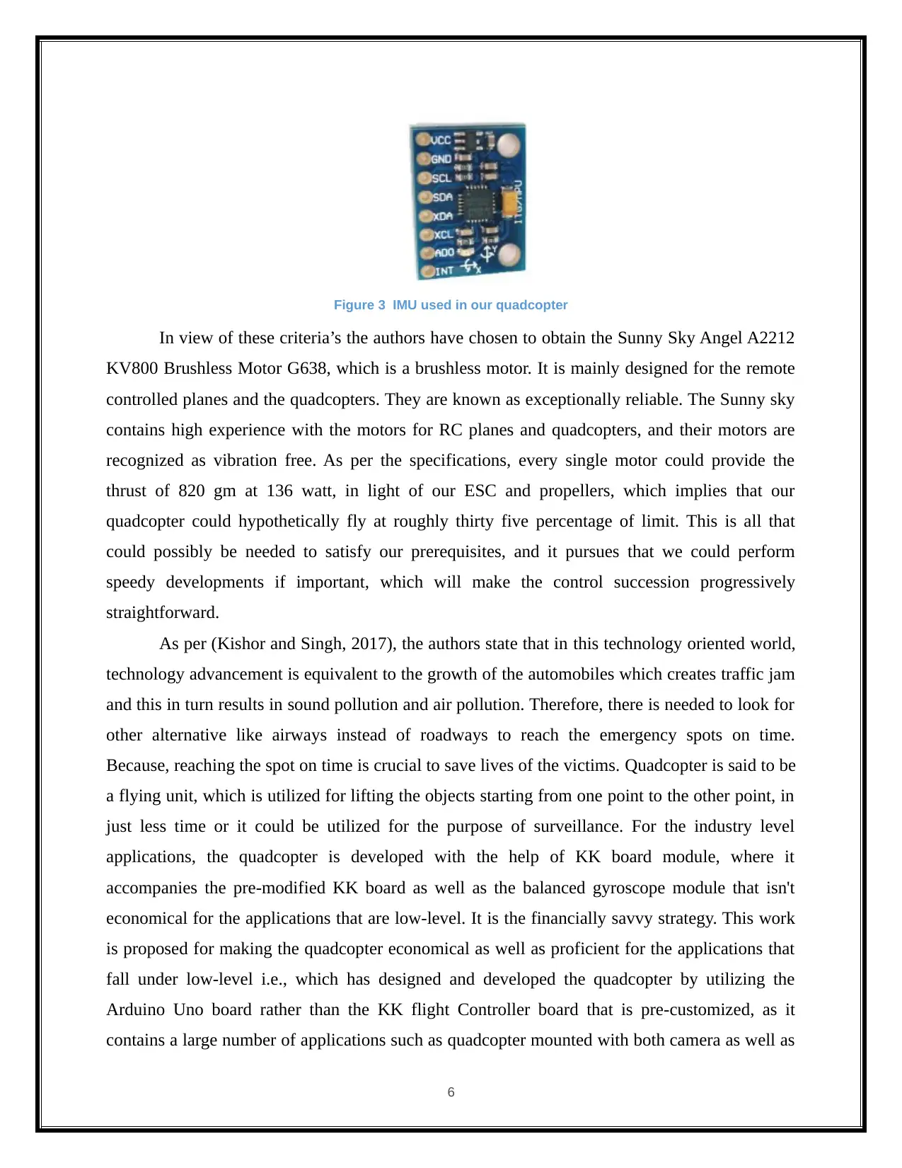
Figure 3 IMU used in our quadcopter
In view of these criteria’s the authors have chosen to obtain the Sunny Sky Angel A2212
KV800 Brushless Motor G638, which is a brushless motor. It is mainly designed for the remote
controlled planes and the quadcopters. They are known as exceptionally reliable. The Sunny sky
contains high experience with the motors for RC planes and quadcopters, and their motors are
recognized as vibration free. As per the specifications, every single motor could provide the
thrust of 820 gm at 136 watt, in light of our ESC and propellers, which implies that our
quadcopter could hypothetically fly at roughly thirty five percentage of limit. This is all that
could possibly be needed to satisfy our prerequisites, and it pursues that we could perform
speedy developments if important, which will make the control succession progressively
straightforward.
As per (Kishor and Singh, 2017), the authors state that in this technology oriented world,
technology advancement is equivalent to the growth of the automobiles which creates traffic jam
and this in turn results in sound pollution and air pollution. Therefore, there is needed to look for
other alternative like airways instead of roadways to reach the emergency spots on time.
Because, reaching the spot on time is crucial to save lives of the victims. Quadcopter is said to be
a flying unit, which is utilized for lifting the objects starting from one point to the other point, in
just less time or it could be utilized for the purpose of surveillance. For the industry level
applications, the quadcopter is developed with the help of KK board module, where it
accompanies the pre-modified KK board as well as the balanced gyroscope module that isn't
economical for the applications that are low-level. It is the financially savvy strategy. This work
is proposed for making the quadcopter economical as well as proficient for the applications that
fall under low-level i.e., which has designed and developed the quadcopter by utilizing the
Arduino Uno board rather than the KK flight Controller board that is pre-customized, as it
contains a large number of applications such as quadcopter mounted with both camera as well as
6
Paraphrase This Document
Need a fresh take? Get an instant paraphrase of this document with our AI Paraphraser
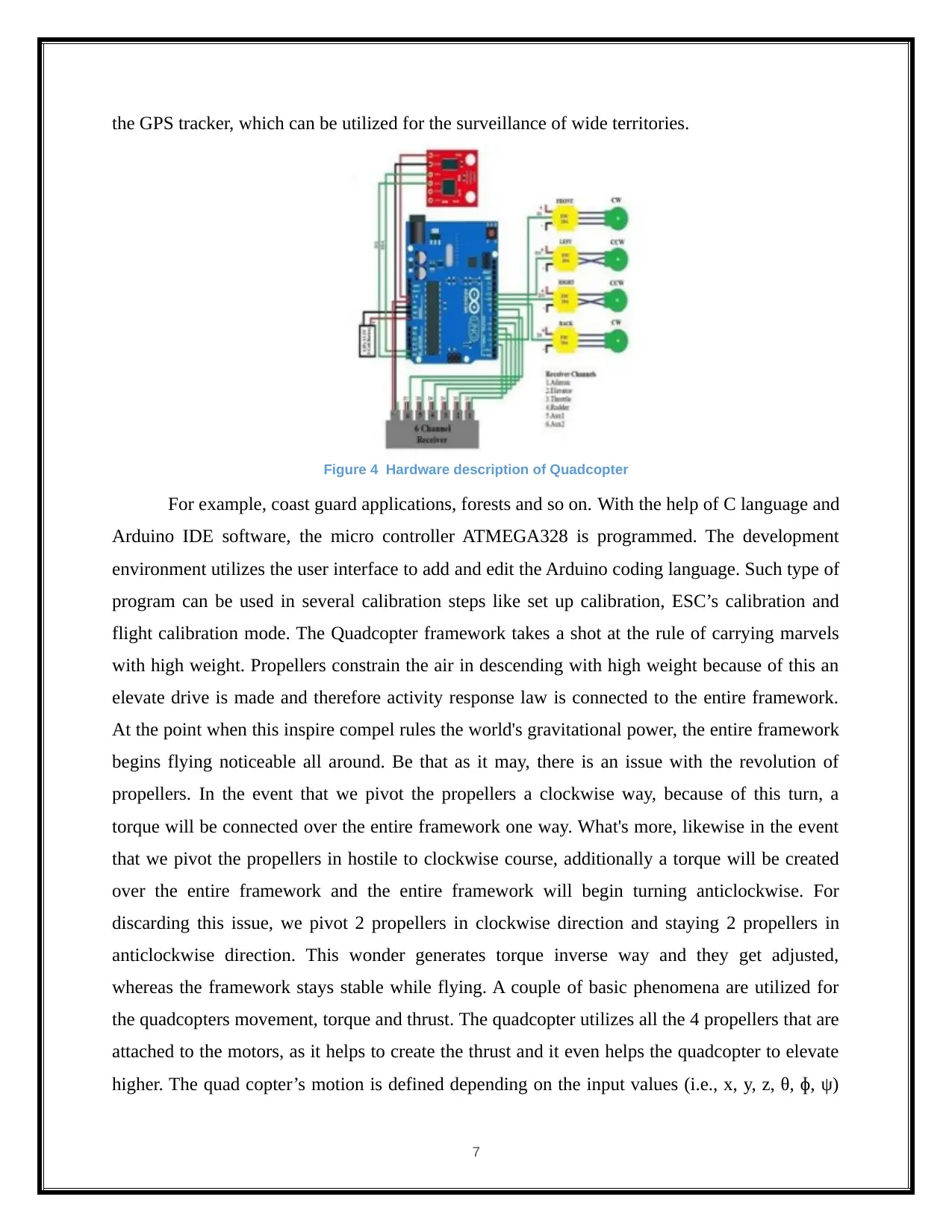
the GPS tracker, which can be utilized for the surveillance of wide territories.
Figure 4 Hardware description of Quadcopter
For example, coast guard applications, forests and so on. With the help of C language and
Arduino IDE software, the micro controller ATMEGA328 is programmed. The development
environment utilizes the user interface to add and edit the Arduino coding language. Such type of
program can be used in several calibration steps like set up calibration, ESC’s calibration and
flight calibration mode. The Quadcopter framework takes a shot at the rule of carrying marvels
with high weight. Propellers constrain the air in descending with high weight because of this an
elevate drive is made and therefore activity response law is connected to the entire framework.
At the point when this inspire compel rules the world's gravitational power, the entire framework
begins flying noticeable all around. Be that as it may, there is an issue with the revolution of
propellers. In the event that we pivot the propellers a clockwise way, because of this turn, a
torque will be connected over the entire framework one way. What's more, likewise in the event
that we pivot the propellers in hostile to clockwise course, additionally a torque will be created
over the entire framework and the entire framework will begin turning anticlockwise. For
discarding this issue, we pivot 2 propellers in clockwise direction and staying 2 propellers in
anticlockwise direction. This wonder generates torque inverse way and they get adjusted,
whereas the framework stays stable while flying. A couple of basic phenomena are utilized for
the quadcopters movement, torque and thrust. The quadcopter utilizes all the 4 propellers that are
attached to the motors, as it helps to create the thrust and it even helps the quadcopter to elevate
higher. The quad copter’s motion is defined depending on the input values (i.e., x, y, z, θ, ɸ, ψ)
7
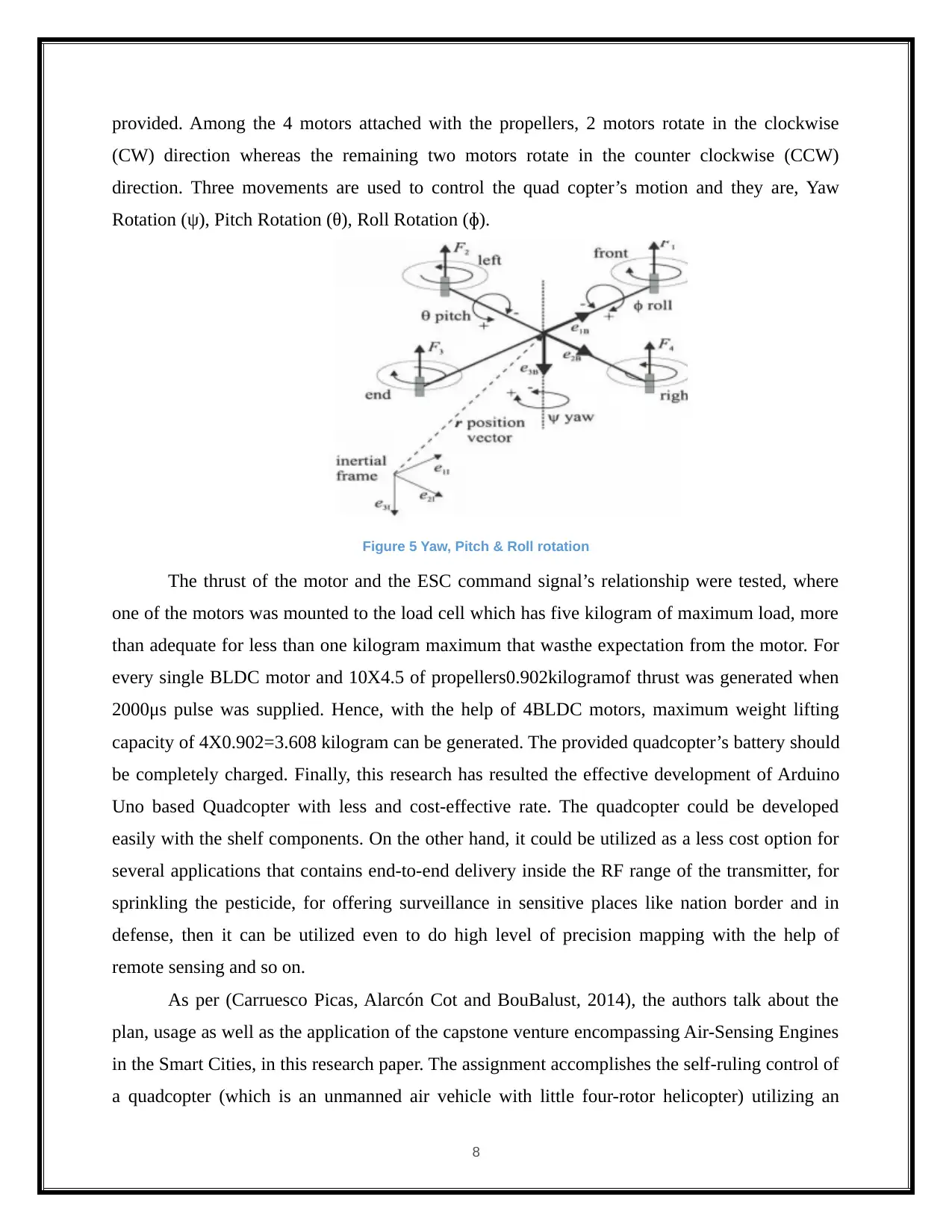
provided. Among the 4 motors attached with the propellers, 2 motors rotate in the clockwise
(CW) direction whereas the remaining two motors rotate in the counter clockwise (CCW)
direction. Three movements are used to control the quad copter’s motion and they are, Yaw
Rotation (ψ), Pitch Rotation (θ), Roll Rotation (ɸ).
Figure 5 Yaw, Pitch & Roll rotation
The thrust of the motor and the ESC command signal’s relationship were tested, where
one of the motors was mounted to the load cell which has five kilogram of maximum load, more
than adequate for less than one kilogram maximum that wasthe expectation from the motor. For
every single BLDC motor and 10X4.5 of propellers0.902kilogramof thrust was generated when
2000μs pulse was supplied. Hence, with the help of 4BLDC motors, maximum weight lifting
capacity of 4X0.902=3.608 kilogram can be generated. The provided quadcopter’s battery should
be completely charged. Finally, this research has resulted the effective development of Arduino
Uno based Quadcopter with less and cost-effective rate. The quadcopter could be developed
easily with the shelf components. On the other hand, it could be utilized as a less cost option for
several applications that contains end-to-end delivery inside the RF range of the transmitter, for
sprinkling the pesticide, for offering surveillance in sensitive places like nation border and in
defense, then it can be utilized even to do high level of precision mapping with the help of
remote sensing and so on.
As per (Carruesco Picas, Alarcón Cot and BouBalust, 2014), the authors talk about the
plan, usage as well as the application of the capstone venture encompassing Air-Sensing Engines
in the Smart Cities, in this research paper. The assignment accomplishes the self-ruling control of
a quadcopter (which is an unmanned air vehicle with little four-rotor helicopter) utilizing an
8
⊘ This is a preview!⊘
Do you want full access?
Subscribe today to unlock all pages.

Trusted by 1+ million students worldwide
1 out of 56
Your All-in-One AI-Powered Toolkit for Academic Success.
+13062052269
info@desklib.com
Available 24*7 on WhatsApp / Email
![[object Object]](/_next/static/media/star-bottom.7253800d.svg)
Unlock your academic potential
Copyright © 2020–2025 A2Z Services. All Rights Reserved. Developed and managed by ZUCOL.
