Automotive Dynamics and Safety: Quarter Car Modeling Assignment
VerifiedAdded on 2023/01/11
|8
|1336
|52
Project
AI Summary
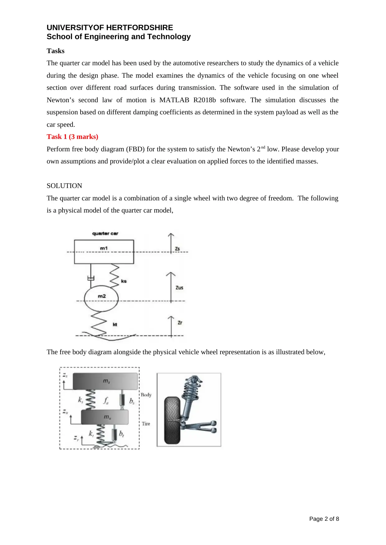
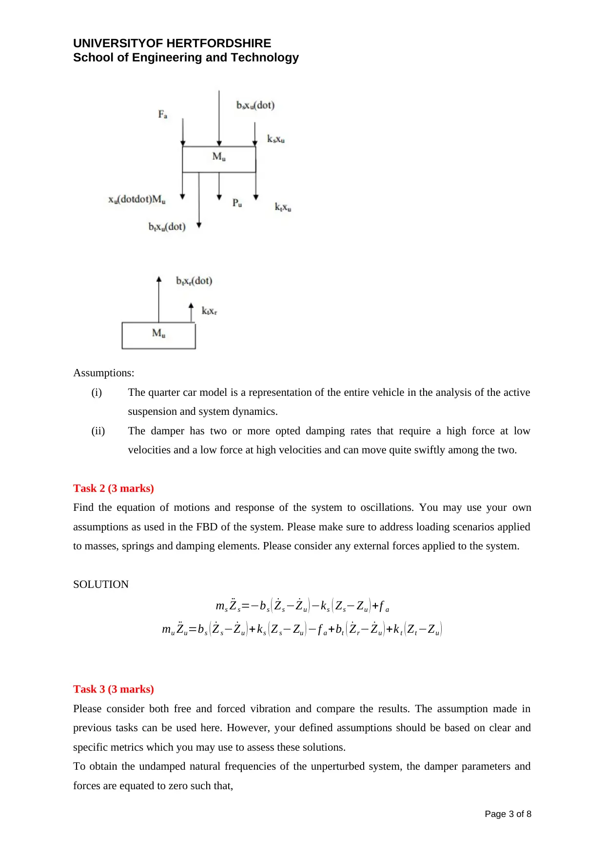
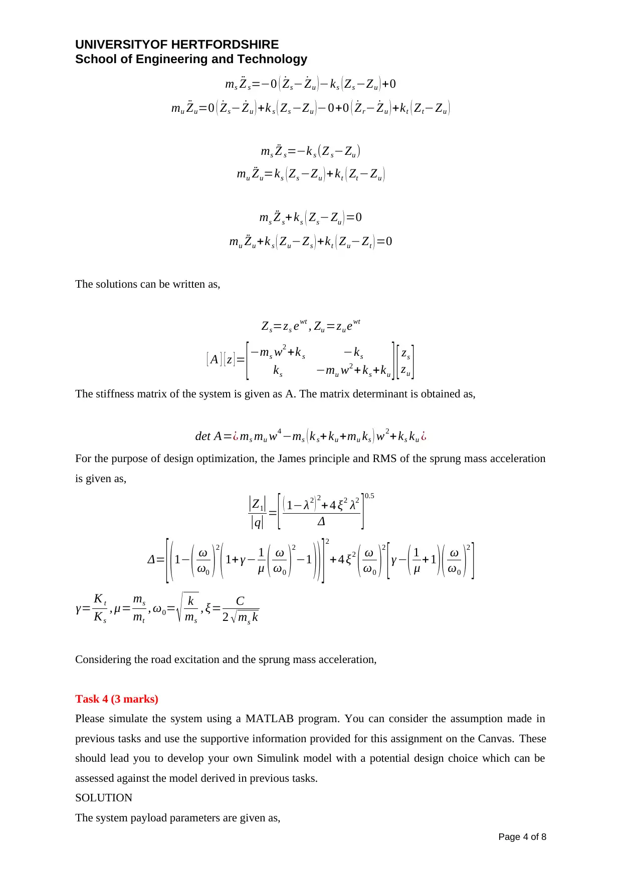
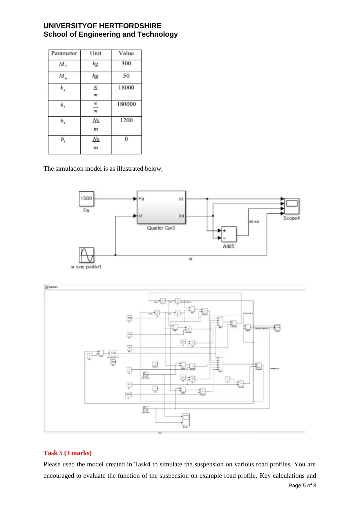
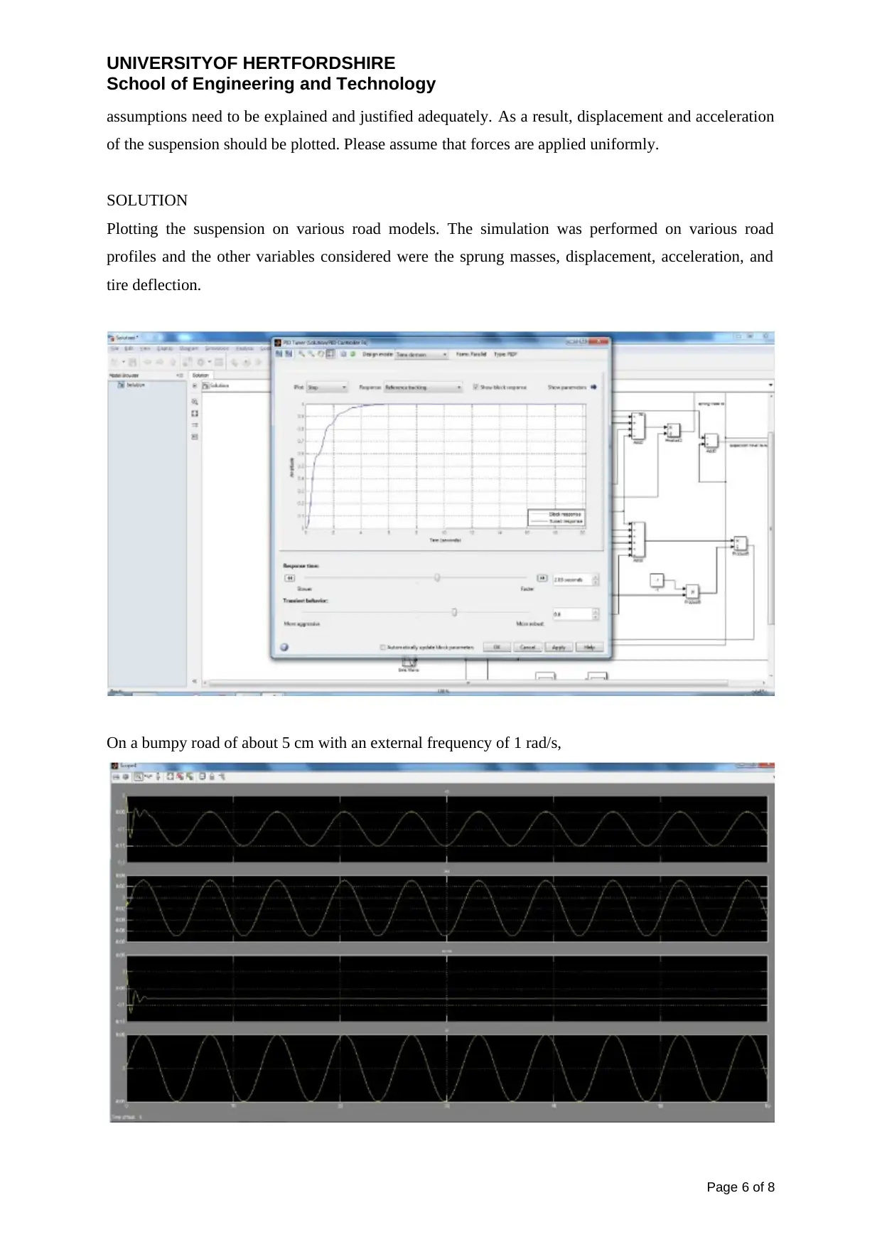
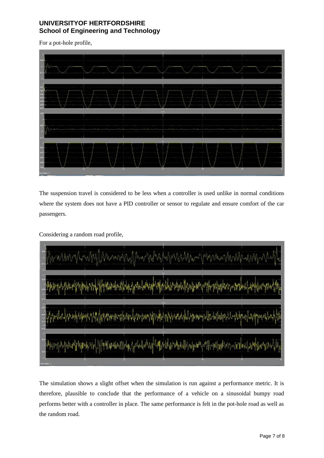
This assignment focuses on the development and analysis of a quarter car model, a simplified representation used in automotive engineering to study vehicle dynamics, particularly the behavior of the suspension system. The student was tasked with creating a free body diagram, deriving the equations of motion, and analyzing both free and forced vibrations of the system. The solution includes assumptions related to the model, such as the representation of the entire vehicle and the characteristics of the damper. A significant portion of the assignment involved simulating the quarter car model using MATLAB and Simulink, where the student developed a model based on parameters provided in the assignment brief. The simulation was then used to evaluate the suspension's performance under various road profiles, including bumpy, pothole, and random road scenarios, plotting the displacement and acceleration of the suspension to assess its effectiveness. The solution also includes references to relevant academic sources.
1 out of 8


Your All-in-One AI-Powered Toolkit for Academic Success.
+13062052269
info@desklib.com
Available 24*7 on WhatsApp / Email
![[object Object]](/_next/static/media/star-bottom.7253800d.svg)
Copyright © 2020–2026 A2Z Services. All Rights Reserved. Developed and managed by ZUCOL.