Network Analysis for uSoft HQ Expansion: User Requirements, LAN Setup, and Design
VerifiedAdded on 2023/04/25
|13
|2009
|382
Assignment
AI Summary
In this document we will discuss about Network Analysis for uSoft HQ Expansion and below are the summary points of this document:-
The report focuses on network analysis and design for the expansion of uSoft HQ, including user requirements and LAN setup analysis.
It outlines the proce...
Read More
Contribute Materials
Your contribution can guide someone’s learning journey. Share your
documents today.

Running head: NETWORK ANALYSIS FOR USOFT HQ EXPANSION
Network Analysis for uSoft HQ Expansion
Name of the Student
Name of the University
Author Note
Network Analysis for uSoft HQ Expansion
Name of the Student
Name of the University
Author Note
Secure Best Marks with AI Grader
Need help grading? Try our AI Grader for instant feedback on your assignments.
1NETWORK ANALYSIS FOR USOFT HQ EXPANSION
Executive Summary
The document aims to study network requirements and design the required diagrams for both
the network and physical levels to represent the final network of uSoft.com. These are the
physical and logical network diagrams. To accomplish this, all user requirements are
documented and the LAN setup of uSoft.com is analysed. Extra resources that necessary for
completing the uSoft HQ expansion have been calculated by noting all the different endpoints
and components relating to the network. This required a set of assumptions to be made on
part of the report which are listed after thoroughly analysing the requirements. In conclusion,
the report clearly illustrates implementing the network following the said expansion. The
report successfully details how connections to devices of every floor of the branches will
exist and how they are interconnected with that of uSoft HQ. The calculations behind IP
addresses allocation and creation of subnets from the main network is shown carefully in an
order that is simple to understand. The measures adopted to secure the network and its nodes
are also mentioned in relevant sections.
2NETWORK ANALYSIS FOR USOFT HQ EXPANSION
Table of Contents
Introduction................................................................................................................................3
Discussion..................................................................................................................................3
Organizational Description....................................................................................................3
User Requirements Analysis..................................................................................................3
Assumptions Drawn...........................................................................................................4
Logical Design.......................................................................................................................5
IP address allocation plan:.....................................................................................................6
Logical Network Diagram......................................................................................................7
Physical Network Diagram....................................................................................................9
Conclusion................................................................................................................................10
Bibliography.............................................................................................................................11
3NETWORK ANALYSIS FOR USOFT HQ EXPANSION
Introduction
The report documents the user requirements for implementing the network and
analyses the LAN of the headquarters (uSoft HQ). The expansion of the headquarters requires
necessary calculations to be conducted for the different endpoints of the network along with
designing of both logical and physical diagrams of the network. In accomplishing this few
assumptions have been made after summarizing of requirements for uSoft headquarters to
present a complete view of the final network. The study shortly describes the organization
and its work and thereafter details an account of all the critical parts of the final network in
the logical as well as physical level.
Discussion
Organizational Description
Over a span of 30 years, uSoft is successfully providing software suites for the field of
biomedical engineering. It has two separate branches that are positioned along the Gold
Coast. The company’s solutions continue to aid businesses to take informed decisions,
manage privacy as well as biometric authenticatio.
User Requirements Analysis
Branch Name Employee Count Server Count Number of
connections
Floor Count
uSoft HQ 70 9 70*2(IP Phone +
PC) + 9 = 149
6
First Branch 8 1 8*2(IP Phone +
PC) + 1 = 17
1
Second Branch 8 1 8*2(IP Phone + 1
Secure Best Marks with AI Grader
Need help grading? Try our AI Grader for instant feedback on your assignments.

4NETWORK ANALYSIS FOR USOFT HQ EXPANSION
PC) + 1 = 17
HQ to B1 2
HQ to B2 2
Total 86 11 187 8
From the major network - 172.16.123.0/22 five subnets have been created. These subnets are
used in providing connections for the headquarters, first branch, second branch, HQ - branch
2 and HQ - branch 1 respectively.
Security of the network is ensured by a leading professional corporate firewall suite which
exists at the headquarters.
Assumptions Drawn
For each branch number of devices total to 17. These include connections for PCs, IP phones
of all the departments and the server.
For the branches all the departments exist in the same floor.
The branches are assumed to have 8 employees each.
For branches and the headquarters, connections to individual devices are provided through
wireless access points.
Each server is connected directly.
The router of the headquarters passes on the secured network to the specific router each
branch using two dedicated switches.
5NETWORK ANALYSIS FOR USOFT HQ EXPANSION
Logical Design
The front line security of the network ensured by an industry standard firewall suite
that is installed in the headquarters of the company. Screened by the firewall, internet
connection of the company gets secured even before reaching the router at uSoft HQ thus
providing a security umbrella for the entire network(Wang et al. 2013). The individual PCs
also have antivirus/antimalware solutions installed that keeps company’s assets from being
compromised from external devices (external hard disks, pen drives) even if the main
network got infected.
These individual devices including IP phones are connected to the network with the
help of wireless access points. This eliminates the worries of buying excess ethernet cables
and the solves the problem of cable management complicacies inside the offices which often
resulted in cable damages by wear and tear.
Virtual local area network (VLAN) connections do exist in offices of uSoft HQ and
the two branches to enable remote access features like shared printers per floor and remote
desktop controls.

6NETWORK ANALYSIS FOR USOFT HQ EXPANSION
IP address allocation plan:
The given Student ID is 23039032
Range of IP Address: 172.16.1XY.0/22 (where X and Y denotes the first and second digit of
the Student ID 172.16.123.0/22
Total possible connections from the major network = 1024 - 2 = 1022
IP addresses of 172.16.123.0/22 placed within 128 and 192 will definitely be class B
Subnet mask for Class B IP addresses – 255.255.0.0 since the CIDR value by default is 16.
For CIDR = 22, subnet becomes 255.255.252.0
This is due to borrowing of six additional bits from the host (27+ 26+ 25+ 24+ 23+ 22 = 252)
Total possible networks – 26 = 64 (6 - number of borrowed bits)
Total possible IP addresses for every network created – (22 - 2) = 2 (2 – remaining number of
host bits)
But the maximum number of connections is only 127
For CIDR =24,
Range of IP addresses: 172.16.123.0/24
Subnet mask turns 255.255.255.0
Total possible networks – 20 = 1 as no bits were borrowed from host.
Total possible IP addresses for every network – (28 - 2) = 254 (8 - remaining number of host
bits)
The IP addresses that are allocated for devices of the headquarters range from 172.16.120.0
to 172.16.120.255 which refers to IPs 172.16.120.1 - 172.16.120.254
Paraphrase This Document
Need a fresh take? Get an instant paraphrase of this document with our AI Paraphraser
7NETWORK ANALYSIS FOR USOFT HQ EXPANSION
The two branches have a total of 20 network connections allocated for each.
For CIDR = 27, subnet mask - 255.255.255.224
This is due to borrowing of 3 additional bits (27+ 26+ 25 = 224)
Connections for every network – 254 – 224 = 30
The IP addresses range from 172.16.121.0 and 172.16.121.32 which refers to IPs
172.16.121.1 – 172.16.121.30 and IPs 172.16.121.33 – 172.16.121.62 respectively.
It is estimated that 2 IPs will be required to connect each of the branches with the
headquarters.
For CIDR = 30, subnet mask - 255.255.255.252
This is due to borrowing of 6 additional bits (27+ 26+ 25+ 24+ 23+ 22) = 252
This provides network addresses of 172.16.121.64 and 172.16.121.68 with assignable IPs
172.16.121.65 - 172.16.121.66 and IPs172.16.121.69 - 172.16.121.70
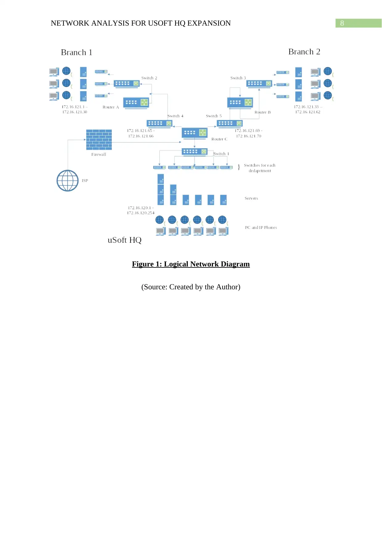
Logical Network Diagram
A Logical network diagram as per the OSI model contain system information concerning the
network layer. This network layer being third layer of OSI model facilitates forwarding data
through routers and switches in the form of packets (Bora et al. 2014). The logical diagram
for the network of uSoft is given below.
8NETWORK ANALYSIS FOR USOFT HQ EXPANSION
Figure 1: Logical Network Diagram
(Source: Created by the Author)
Figure 1: Logical Network Diagram
(Source: Created by the Author)
9NETWORK ANALYSIS FOR USOFT HQ EXPANSION
Physical Network Diagram
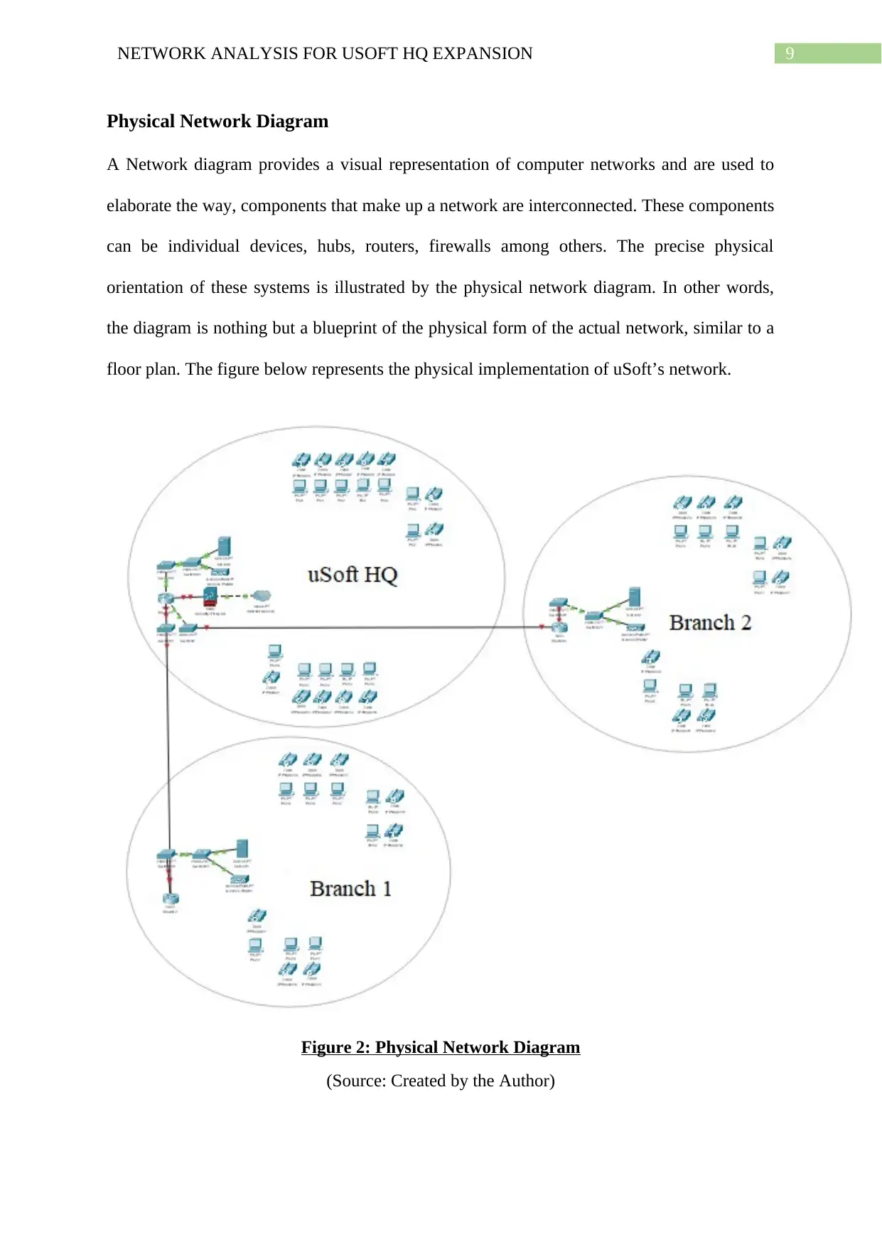
A Network diagram provides a visual representation of computer networks and are used to
elaborate the way, components that make up a network are interconnected. These components
can be individual devices, hubs, routers, firewalls among others. The precise physical
orientation of these systems is illustrated by the physical network diagram. In other words,
the diagram is nothing but a blueprint of the physical form of the actual network, similar to a
floor plan. The figure below represents the physical implementation of uSoft’s network.
Figure 2: Physical Network Diagram
(Source: Created by the Author)
Secure Best Marks with AI Grader
Need help grading? Try our AI Grader for instant feedback on your assignments.
10NETWORK ANALYSIS FOR USOFT HQ EXPANSION
Conclusion
In conclusion the report fully explains the network implementation following the uSoft.com
headquarter expansion. It successfully details how the connections of devices in a given floor
may exist and the way the setups of the branches are interconnected with that of uSoft HQ.
The IP address allocation process is carefully documented in the simplest order while also
specifying the necessary calculations required to create the different subnets of the network
for the specific purposes as mentioned in requirements. The report also discusses relevant
information on measures taken to secure the network and its components.
11NETWORK ANALYSIS FOR USOFT HQ EXPANSION
Bibliography
Bora, G., Bora, S., Singh, S. and Arsalan, S.M., 2014. OSI reference model: An
overview. International Journal of Computer Trends and Technology (IJCTT), 7(4), pp.214-
218.
Chittimaneni, K., Chown, T., Howard, L., Kuarsingh, V., Pouffary, Y. and Vyncke, E.,
2014. Enterprise IPv6 Deployment Guidelines (No. RFC 7381).
Holappa, M., 2013. Performance Comparison of LTE ENODEB OSI Layer 2
Implementations; Preemptive Partitioned Scheduling vs. Non-Preemptive Global
Scheduling. Master's Thesis, Degree Programme in Information Networks.
Levin, D., Canini, M., Schmid, S., Schaffert, F. and Feldmann, A., 2014. Panopticon:
Reaping the benefits of incremental sdn deployment in enterprise networks. In USENIX
Annual Technical Conference (pp. 333-345). USENIX Association.
Popovic, G., Arsic, N., Jaksic, B., Gara, B. and Petrovic, M., 2013. Overview, characteristics
and advantages of IP Camera video surveillance systems compared to systems with other
kinds of camera. Int. J. Eng. Sci. Innov. Technol, 2(5), pp.356-362.
Priyadharson, A.S.M., Joshua, S.V. and ThilipKumar, C., 2015. PLC–HMI and ethernet based
monitoring and control of mimo system in a petrochemical industry. Indian Journal of Science and
Technology, 8(27).
Schindelin, J., Rueden, C.T., Hiner, M.C. and Eliceiri, K.W., 2015. The ImageJ ecosystem: an open
platform for biomedical image analysis. Molecular reproduction and development, 82(7-8), pp.518-
529.
Shang, W., Yu, Y., Droms, R. and Zhang, L., 2016. Challenges in IoT networking via TCP/IP
architecture. Technical Report NDN-0038. NDN Project.

12NETWORK ANALYSIS FOR USOFT HQ EXPANSION
USoft.com (2019). Home. [online] USoft.com. Available at: https://www.usoft.com/
[Accessed 2 Feb. 2019].
Wang, Y., Li, J., Meng, K., Lin, C. and Cheng, X., 2013. Modeling and security analysis of
enterprise network using attack–defense stochastic game Petri nets. Security and
Communication Networks, 6(1), pp.89-99.
1 out of 13
Related Documents
Your All-in-One AI-Powered Toolkit for Academic Success.
+13062052269
info@desklib.com
Available 24*7 on WhatsApp / Email
![[object Object]](/_next/static/media/star-bottom.7253800d.svg)
Unlock your academic potential
© 2024 | Zucol Services PVT LTD | All rights reserved.


