Vehicle Systems and Technology Report - Edexcel BTEC HND Unit 75
VerifiedAdded on 2023/01/19
|9
|1712
|33
Report
AI Summary
This report delves into the intricacies of vehicle systems and technology, focusing on steering and suspension systems. Task 1 dissects the components of a manual steering system, contrasting it with electric power steering and exploring the advantages of the latter. It further examines various speed sensors, including variable reluctance, Hall Effect, eddy current, Doppler radar, and LIDAR sensors. Task 2 analyzes a hydraulic steering system, explaining its operation from "NO TURN" to "RIGHT TURN" positions, identifying it as a non-independent suspension system, and outlining its components. Task 3 covers testing procedures for torque sensing, potential faults, and diagnostic methods, including inspection, fluid checks, and component replacement or repair, referencing relevant sources. The report provides a comprehensive overview of vehicle systems, essential for understanding automotive engineering.
VEHICLE SYSTEMS & TECHNOLOGY
By Name
Course
Instructor
Institution
Location
Date
By Name
Course
Instructor
Institution
Location
Date
Paraphrase This Document
Need a fresh take? Get an instant paraphrase of this document with our AI Paraphraser
Task 1
1-Tie rod end: Aid in pushing and pulling the front tires when the wheels turn
2-Screw plug: Prevent adjustments of idle jet when emission occurs
3-Pinion shaft: Transfer of input of driving shaft to other axle gears
4-Tie rod: Aid in pushing and pulling the front tires when the wheels turn
5-Ball nut: Changes rotational motion to linear motion (Ataei et al., 2017)
6-Steering gear housing: Changing steering wheel movement into front wheel movement
7-Rack: Transmission of the load of the body
(a) The system is a manual steering system. A manual steering system depends on the string
system in which steering is linked to a rod which rotates the wheels according to the direction of
rotation. This is terms as the rack and pinion steering where rack means rod and the pinion
defines gear (Omar, El-Kassaby and Abdelghaffar, 2017). A gear is linked to the steering rod
such that when the driver turns the steering wheel on; the gear is turned in a circular motion and
thus moves the steering rod that may be seen behind the clutch, accelerator pedal as well as brake
pedal.
(c) Electric power steering has gained popularity and become more common as time passes on,
an indication that a good number of the automotive engineers are tending to believed there are
more advantages in comparison with the hydraulic systems (Un-Noor et al., 2017). Among the
advantages include:
Minimal mechanical complexity alongside less weight resulting in fuel economy and efficiency
Energy efficiency as the power steering pump works as a parasitic device every time in which
the electric motor just requires energy when turning
Easier interface with self-driving smart brains
Capability of easily changing various levels of assistances depending on the modes of driving
A sensor is a device that is used in the detection of the changes that occurs in the physical,
electrical or even other quantities and hence generating an output as an acknowledgment of
variation in the quantity. A speed sensor is used in the detection of the speech of a vehicle or
object. There are different kinds of sensors in the detection of speed including wheel speed
sensors, ground speed radar, Doppler radar, LIDAR, speedometers, pedometer logs, pitot tubes,
and air speed indicators among others.
Variable reluctance speed sensors: These work by changing mechanical motion into electric
energy without going through direct contact when placed near a shaft, gear, rotor or any other
device that is regularly moving. The sensor is composed of a coil of wire wound about a
cylindrical magnetic material known as pole piece.
Hall Effect and eddy current sensors make use of Hall Effect traducer element that sis placed
between the tagged and the magnet. A Hall transducer is very sensitive to the magnetic flux and
does not detect changes in the rate.
Eddy current speed sensors: Eddy currents are closed loops that have induced current flowing in
planes that are perpendicular to the magnetic flux (Kumar, McCann, Naughton and Patel, 2016).
The direction of their travel is often parallel to the winding of the coil and the flow is restricted
to the region of the inducing magnetic field (Giovanardi et al., 2016).
⊘ This is a preview!⊘
Do you want full access?
Subscribe today to unlock all pages.

Trusted by 1+ million students worldwide
Radar Doppler speed sensor: An echo of radar that is sent in the direction of a moving target
would have a shift in the frequent and the shift is related to the speed of the moving object. Upon
the approach of the target, the Doppler shifts would be more while when the target moves away,
the shift in the Doppler increases and this forms the basis of taking measurements of the target
velocity.
LIDAR speed traps: These make use of the technique of standard pulse time of fight
measurement with the use of a micro-controller which processes the measured values in the
estimation of the speed as well as position of the targeted. A tracking filter is used in the
estimation of the velocity or through taking measurements of the changes in the range as
calculated by the varying flight time between successive pulses.
Task 2
Paraphrase This Document
Need a fresh take? Get an instant paraphrase of this document with our AI Paraphraser
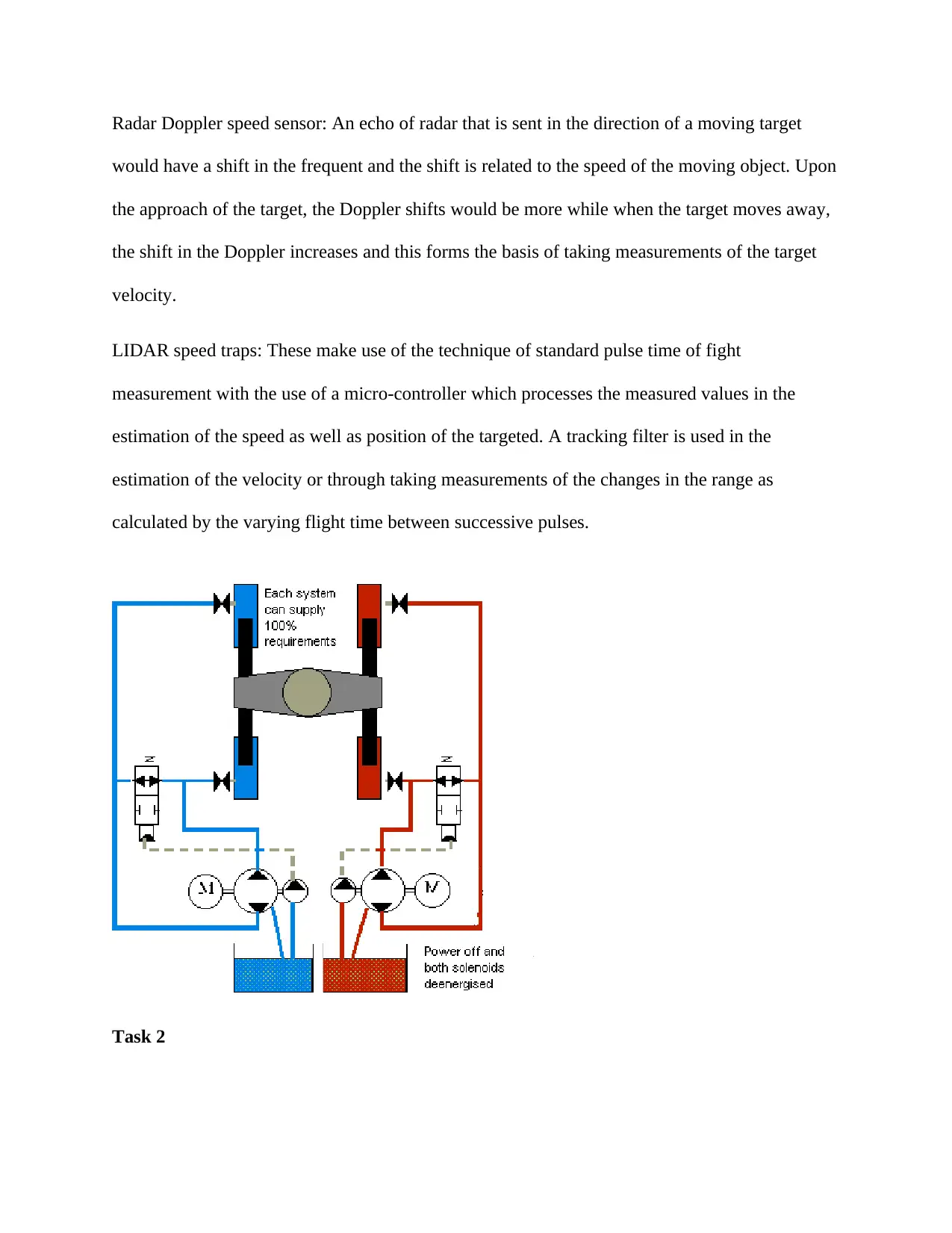
A) What is the name of the system in the following figure? To which type of steering system
it belongs?
Suspension system
It belongs to the hydraulic types of steering system
B) Explain its operation in a paragraph from the “NO TURN” position on left to “RIGHT
TURN” position on right.
The system houses the differential of the vehicle within the axle itself, linked to the wheels using
rigid half-shafts. The whole axle moves as a single one, such that in case a left wheel drops into
potholes, there is movement of the wheel upwards in response (Huang et al., 2018). With an
independent suspension the differential unit does not form part of axle and instead the
differential is linked to chassis and power is transmitted to every wheel using driveshaft. Since
the differential does not undergo motion with the axle, every wheel may have an independent
suspension link to vehicle. In case there is a drop in the left wheel into a pothole, there is no
movement in the right wheel.
C1) type of the suspension systems above (independent, non-independent)
This is a non-independent suspension system. It has a rigid linkage between the two wheels of
the same axle and hence a force that acts on one of the wheels will affect the opposite wheel tool
(Thakur, 2016). For every motion as a result of road irregularities, the effect is felt by the
coupled wheels too.
C2) specific type names of the systems (MacPherson, twin beam, and exc.)
Solid Axial suspension system
C3) the names of the numbered components

6-Axle housing: Contains the axle and bearings which allow free rotation of wheel
3-Center link: Links the steering gearbox to the pitman arm
4-Anti sway bar: Lowers the body roll of a car during fast cornering
5-Stabilizer bar: Prevent the car from too much leaning and maintains it in a stable position
1-Shock absorber: Limit the overall movement of the vehicle
2-Coil springs: Store energy and release the same to absorb shock
7-Power steering gearbox: Changing the rotary motion of the steering wheel into linear motion
Task 3
(a) Testing of torque sensing
Take measurement of the resistance torque connector terminal
Replace the steering gear and linkage in case of any malfunction
Check loosening of steering wheel
Move the steering wheel in the direction of shaft and in directions of four right angles
Inspect the following in case of any malfunction and replace or repair as needed
Steering wheel effort
Verify equipped tire size as well as tire air pressure is as indicated (Reybrouck, 2016)
Put wheels in the straight ahead position with vehicle on level and hard surface
Remove air bag module
Start engine and idle it
Confirm that EPS warning light is not illuminating
Use torque wrench to confirm steering wheel effort
⊘ This is a preview!⊘
Do you want full access?
Subscribe today to unlock all pages.

Trusted by 1+ million students worldwide
(b) Faults may include
Malfunction of components
Open as well as short circuit
System adjustments
Methods usable in diagnosis and testing include:
Removal
Service and repair adjustments
Pre- and post-service/repair testing of system as well as component operation
Testing Procedure
Conduct an inspection on the shock mounts and rubber cushions
Check for the leaks of fluids
In case outside of shock is destroyed, replace both the shocks
Signs of contact are indicated by rubber bump stops
Investigate the shock mounts
Check the air shock which at times fail in case a hole is found in its rubber bladder
Paraphrase This Document
Need a fresh take? Get an instant paraphrase of this document with our AI Paraphraser
References
Ataei, M., Asadi, E., Goodarzi, A., Khajepour, A. and Khamesee, M.B., 2017. Multi-objective
optimization of a hybrid electromagnetic suspension system for ride comfort, road holding and
regenerated power. Journal of Vibration and Control, 23(5), pp.782-793
Giovanardi, M., Leehey, J.R., Schneider, J. and Anderson, Z.M., ClearMotion Inc, 2016. Context
aware active suspension control system. U.S. Patent 9,440,507
Huang, Y., Na, J., Wu, X. and Gao, G., 2018. Approximation-free control for vehicle active
suspensions with hydraulic actuator. IEEE Transactions on Industrial Electronics, 65(9),
pp.7258-7267
Kumar, A., McCann, R., Naughton, J. and Patel, J.M., 2016. Model selection management
systems: The next frontier of advanced analytics. ACM SIGMOD Record, 44(4), pp.17-22
Omar, M., El-Kassaby, M.M. and Abdelghaffar, W., 2017. A universal suspension test rig for
electrohydraulic active and passive automotive suspension system. Alexandria Engineering
Journal, 56(4), pp.359-370
Reybrouck, K., Tenneco Automotive Operating Co Inc, 2016. Passive and active suspension
with optimization of energy usage. U.S. Patent 9,481,221
Thakur, R., 2016. Scanning LIDAR in Advanced Driver Assistance Systems and Beyond:
Building a road map for next-generation LIDAR technology. IEEE Consumer Electronics
Magazine, 5(3), pp.48-54

Un-Noor, F., Padmanaban, S., Mihet-Popa, L., Mollah, M. and Hossain, E., 2017. A
comprehensive study of key electric vehicle (EV) components, technologies, challenges,
impacts, and future direction of development. Energies, 10(8), p.1217
comprehensive study of key electric vehicle (EV) components, technologies, challenges,
impacts, and future direction of development. Energies, 10(8), p.1217
⊘ This is a preview!⊘
Do you want full access?
Subscribe today to unlock all pages.

Trusted by 1+ million students worldwide
1 out of 9
Your All-in-One AI-Powered Toolkit for Academic Success.
+13062052269
info@desklib.com
Available 24*7 on WhatsApp / Email
![[object Object]](/_next/static/media/star-bottom.7253800d.svg)
Unlock your academic potential
Copyright © 2020–2025 A2Z Services. All Rights Reserved. Developed and managed by ZUCOL.

